The AUAV X2.1 is all about lessons learned. The X2 was a very successful board but there was still room for improvement. Following the PixRacer project we had time to invest into making the X2 the high quality PixHawk replacement we intended it to be. Major changes include: updated IMU sensors, power supply has been redesigned, headers have been laid out more logically, remote USB connector, industry standard 30.5mm mounting points.
New Power OR-ing schematic with reverse voltage protection. 5V power module is required!
Connections:
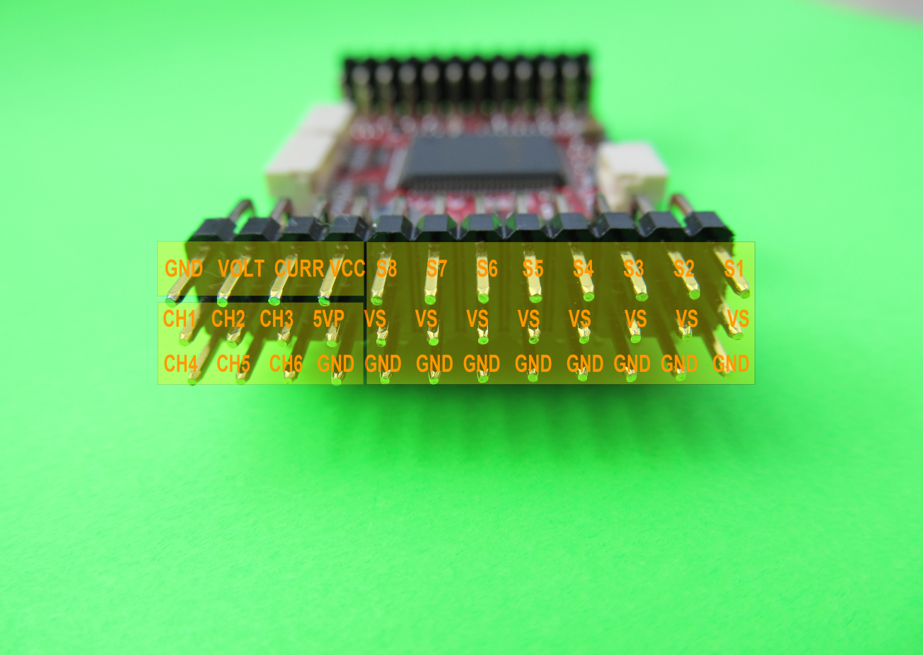
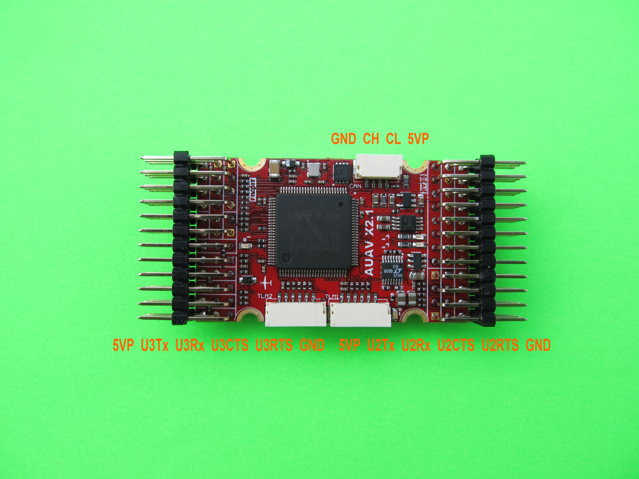
2.54mm headers:
GPS (USART4)
i2c
RC input
PPM input
Spektrum input
RSSI input
sBus input
sBus output
Power input
Buzzer output
LED output
8 x Servo outputs
6 x Aux outputs
USART7 (Console)
USART8 (OSD)
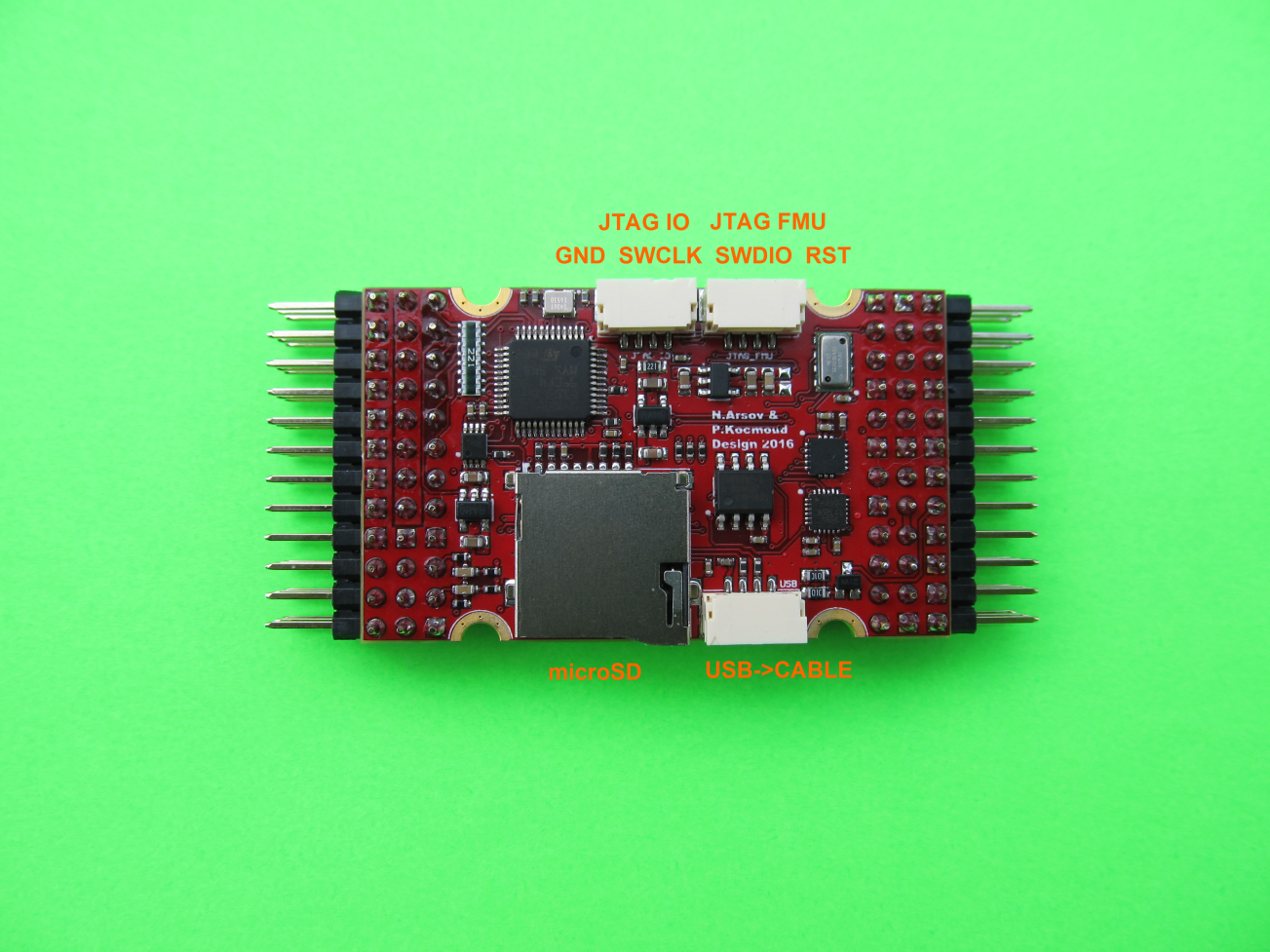
JST GH connectors:
CAN
USART2 with flow control (Telem 1)
USART3 with flow control (Telem 2)
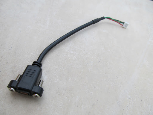
USB (150mm GH to Micro USB cable included for convenient mounting)
JTAG FMU Processor
JTAG IO Processor
Looks great. I like the combination of the 0.1 inch headers with the JST-GH connectors. It has a feel of being an upgrade of the APM2.x. I am working on a STM32F4 powered FC, which I plan to base on FreeRTOS rather than NUTTX. http://discuss.ardupilot.org/t/ardupilot-flight-controller-with-on-chip-osd/11583/2
There is no reason that cant be ported to this board. It would be interesting to comapre NUTTX and FreeRTOS on the same FC ( and indeed other RTOS) to see how they compare.
fantastic
I especially like the extra usb … finally, I would say
very sad that I have already two auav-x2 and don’t need more
btw, is the given dimension 36x50 correct? I see that it’s a bit longer than the auav-x2, but considering it’s also 12 pins it should be something like 30.5, shouldn’t it? Also the half-cut holes suggest that.
is this open source again? In some way I really hope it is not (you said “lessons learned” ;)).
@olliw42 I would hope that there is a schematic available. Sure keep the pcb, Gerbers etc private. If there is no schematic it is kind of saying that we are not very interested in helping people develop for the board and I will heed the advice and go elsewhere
As far as I know you can have a real redundancy only if you have three IMU
The second IMU in original Pixhawk was because they had errors with the first IMU and not being able to solve they add a second IMU, then the problem on the first IMU was solved but the second remains.
I 'am aware that present software only support two IMU but IMO a real step forward would be a real redundancy so three IMU.
3 or 100 IMUs does not give you true redundancy. These small boards still have 1 flight processor and 1 power module. The IMU difference is more suited to handling different vibration frequencies and detecting a failing component rather than being truely redundant.
In accordance to Pareto principle it may give a big reliability growth while spending just minor part of costs on additional IMU handling. IMHO IMUs are much frequently could be a subject of failure than other parts of FMC or PM.
I believe it depends on a purpose for FMC being used. It’s not a big deal for racing drones. And it could be really much important for delivery or mapping drones.
I was thinking about buying one of these from The mro store but I simply see not one example of a anyone reporting that they have successfully deployed this, although it is unlikely there are showstopping issues.
There is a tried and true approach. Supply boards to the regular suspects for evaluation and review here or on RCGroups. Videos made. Feedback noted. Have I missed something? I have seen nothing…
I follow this board from begining, it´s looks nice for my builds but long time to go to market, very few experiences and no answer from developer many times I asked for news, I don´t know if I miss something too but I bought a pixracer just in case…
How did the CAN remain reversed for the X2.1 and yet is correct for the Pixracer? How strange.
Olli – can this not be addressed by swapping around the CAN CH and CL wires on the CAN connector? Obviously not ideal. Maybe I am not understanding fully but I am not sure why you have had to do delicate soldering jobs on your v1 X2 boards rather than swapping the wires.
And given that I am looking for an extra small form factor board for a plane that has CAN functionality I think I may have to pass if I need to do delicate soldering on it. I could live with swapping CAN wires on the CAN connector though…
the X2 is not the X2.1
so what is true for the X2 might be irrelevant to the X2.1, and vice versa
X2.1: here you need to swap the wires in the CAN connector, as you say.
X2: here the PCB is routed incorrectly such that the CAN transceiver can’t work, and if one wants to correct for that one needs to do some delicate soldering. Since this is not something many would do, it effectively makes the CAN on the X2 non-functional.
the X2 thing is irrelevant to the X2.1, and hence OT. I just mentioned it in response to your question, thinking that it may help clarifying the situation. Sorry if it rather added to the confusion.
for the X2.1 holds (and that’s all I wanted to bring to attention):
it has CH and CL reversed on the CAN port
=> needs to be addressed by swapping around the CAN CH and CL wires on the CAN connector
(unless you connect it to a CAN device with the same reversed layout LOL ;))
EDIT: it’s kind of sad since, if you read e.g. Mike Kelly’s posts on UAVCAN, one of the appealing aspects to him is the simplified standardized connection … this practical advantage is a bit broken into pieces
EDIT2: paragraphs 2-4 here: UAVCAN: CANbus for the rest of us
It is not a deal-breaker to have to swap wires, for me anyway, I suppose. Still if we start using CAN for peripherals (and I hope we do) then basically we will need standardization, as you say.
I will say I still like my older X2s. Even though they have had some minor issues, but all of which are still working for me. One of those issues, only relevant now, is a useless CAN port since I now will be playing with CAN peripherals.
Based on some positive feedback here, I may well order one.
I ordered one of these. At $90 including soldered headers, shipping and cables, they have reduced the price by about $20. It seems a better option than a Pix Cube (good but big and pricey) or a Pixhawk 1.
For plane users having the USB by default on flexible cable is a plus.