I have a problem and maybe you can help me. I wanted to calculate the inertia moments of a VTOL and did a bifilar pendulum test. I logged the IMU data from the pixhawk (gyroscope data) and I tracked the angular velocity with a camera tracker and we stopped time and counted the oszillations to have some data for sanity check. In the end the hand measured data and the camera tracker offered very similar data and in y axis (body fixed frame) the IMU had an offset of over 20% and in z-axis of around 10%. The x axis was very similar. We thought of maybe the offset to the rotational axis of the pixhawk has an impact, because the x axis is the only one were the pixhawk lies approximatly in the rotational axis. But for angular velocity there should be no difference. Does anyone no what the issue could be? Maybe some calculations were made in ardupilot?
Thank you so much for helping!!!
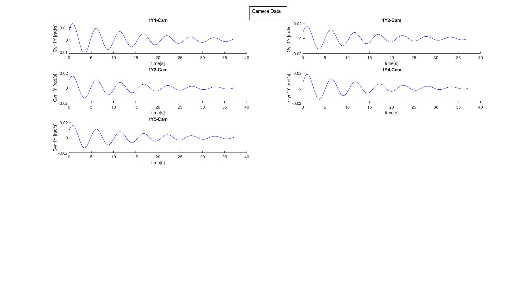
I get the bin data from the SD Card inside the pixhawk and read IMU1 and IMU2 with Gyr x,y or z (depends on the axis) and the time. Does this answer your question? I´m sorry, if I misunderstud it.
There might be a precession happening. That’s a guess from what I’m understanding. The period is the most important thing anyways. How close to the CG are the IMUs? Are the IMUs mounted slightly off the axis of rotation? Does the accelerometer data show the expected period?
It has not very close. I would say in z and y Axis around 30cm.
The Period is different. For a configuration in y Axis the IMU shows a period of 6.6s, the camera tracker 5.4s and the hand measurement (not that accurate) 5.3s. An other setup for the y axis (1 wing removed) says IMU:6.1s Camera:5.6s, Hand 5.4s. Nothing on the rotational axis was changed.
In z-Axis it was IMU:7.5s, Camera:6.8s and Hand: 6.8s
When you are plotting the IMU data, are you using the timestamp with each log message? The data should be recorded at the rate set in the scheduler, but it’s usually a little faster or slower and can change rates.
Actually I used a formula for a damped system and also calculate the damping. It should be x = e^(-deltat)(Acos(omegat)+Bsin(omegat)). For delta is the damping and omega is the damped natural frequency. Than I calcualted the inertia moment is I= (mgd^2)/(4Lomega^2)*(1-delta^2). We have a span of 3.6m and we used a hight of 4.26m for the y axis and 4.59m for the z axis.