Hi Josh
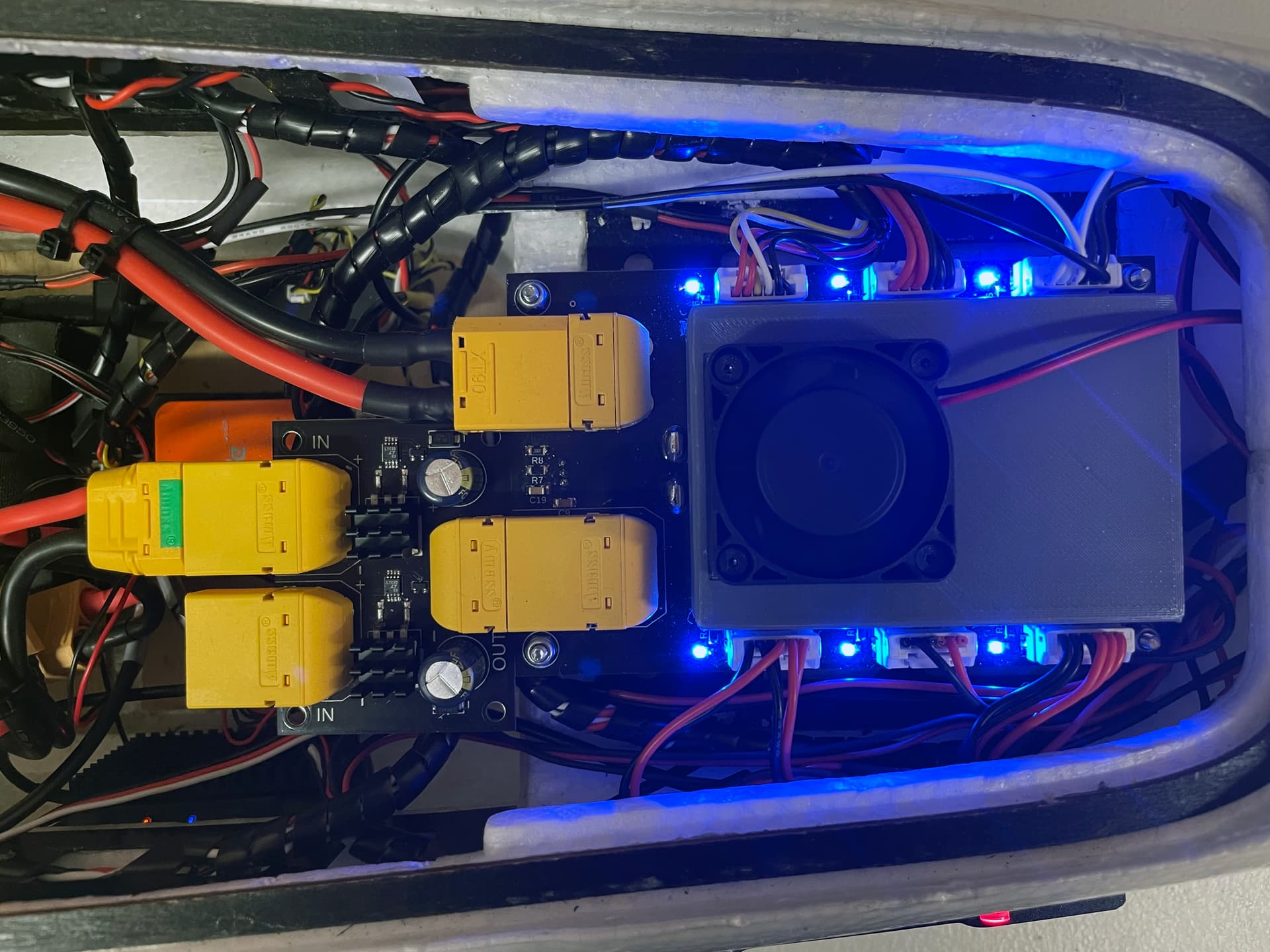
During testing it was enclosed in the fuselage it was plugged directly into the power brick
Do you offer these with open solder pads (no XT90s pre-soldered)?
Hi Manav
Yes I build them so I can leave the XT90’s off
Great! Last question - what is the dual version’s current/voltage rating?
2 x 100v 80A its just 2 single circuits on one board
Awesome! So well stress tested then and no massive amount of airflow like a copter might have.
How can we place an order for the dual unit? This is exactly what we need!
We are running a 12S setup @ around 40-50 Amps.
Very interesting topic, I would also definiately buy some if higher current ones were available.
However there is another issue (maybe not for boats), that has to be considered and that is the active braking of the ESCs. While spooling down all of the motors simultaniously (e.g. on landing), the extra energy that is generated has nowhere to flow and causes huge voltage spikes, which could damage the electronics. Fortunately I caught this issue early on without any damage to components.
Currently I use huge shottky diodes with large heatsinks attached to them for this purpose, which is far from ideal, but there are no alternatives, that I found. I have two 12S 24 Ah batteries in parallel and have limited the current draw to 120 A in Ardupilot. The hovering current without payload is not that much 35-40 A, but with payload this can double. To be safe I would consider using an ideal diode that is designed for 150-200 A.
As for the voltage spike, I used another small diode in reverse with a small fuse in series, which eliminated the problem. This way I have a fully redundant power supply.
Yes, Leonard Hall warned me about this potential voltage spike as well and suggested I might want to attach a large capacitor between the ideal diode and the motor. The size of the diode required though and the annoyance of adding a safe method to charge up the diode made me put this off to the side for now at least…
So far I haven’t seen this issue but the boat motor is very slow to spin up and slow down which I’m sure is different than a multicopter ESC/motor.
Are you getting spikes in the +20V region right? You could try to put a tws diod 47v 5kW between pos/ground , close to the ESC power bus to get rid of it, or significally decrease the spike. It´s hard to filter it out completly. The battery will take care of it normally, but now with a diod in between.
Hi @Tom_Viper
You can get them here
https://uavmapping.co.uk/hawk-power-products/
I have plenty in stock
Jed
I have just ordered the DUAL diode for the FIghter 4-1. Am curious. Looks good in any case.
Ordered on March 30th
I sent an inquiry e-mail to the e-mail below to receive shipping-related information, but it was returned and there is no way to contact me, so I leave it here.
info@uavmapping.co.uk
can you contact me?
I’m trying to reach you by email, but it’s bouncing back. Do you have another email contact?
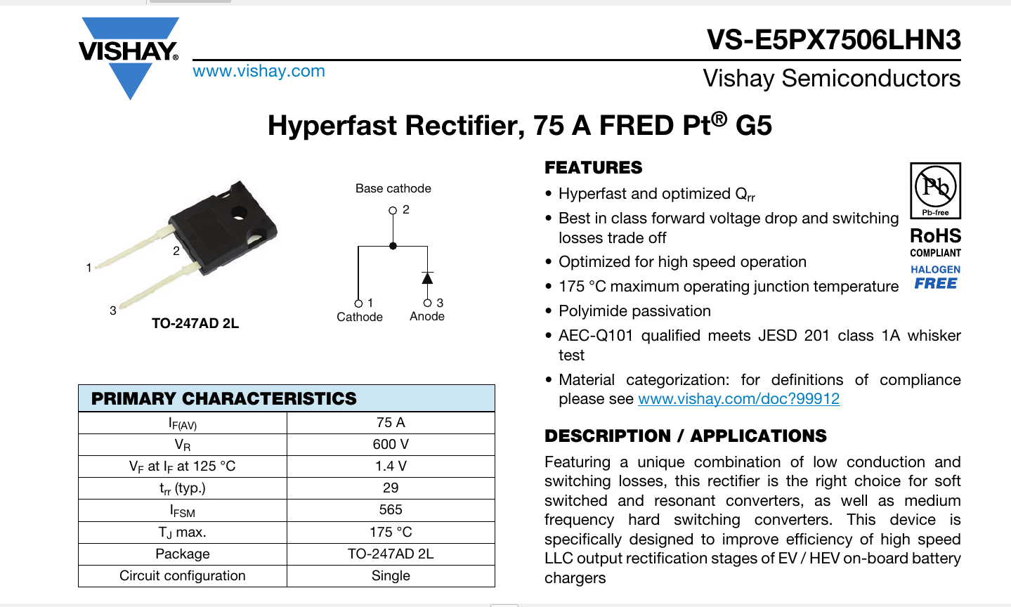
Here is a rectifier Diode which I’m consider using as a backup power source “separator”.
So the idea is having a smaller second battery which also bypasses the PM in the event of an issue with PM or even main battery. - (PM failure / burn out happened to me before)
The idea with the higher trigger voltage is that it prevents any current backflow in normal operation.
If the main power source / PM fails the backup battery would take over and the battery failsafe might be triggered as the PM no longer provides any battery related information.
Those are available in many countries via RS-Components
You can use this to separate two batteries but it has a very high forward voltage, 1.4V. So whatever current you draw through it you multiply by 1.4 and that is the maximum heat you have to get rid of with heatsinking of some sort. 10A would be 14W of power to dissipate or risk destroying the diode by overheating. So yes, you could use it, but it has problems.
The “ideal diodes” further upthread have quite low on resistance so heavy currents create a modest voltage drop, much lower than real diodes, so they can easily be used at higher currents. They are, of course, more complex.
I’m aware of that.
The idea behind the diode with 1.4V drop is to just use it as emergency power switch.
→ If your main source of power fails (battery, small generator, hydrogen fuel cell,…) then it allows for a small backup battery to take over. Ideally even bypassing the PM as this would trigger an alarm / failsafe to make pilot aware of power trouble and allow quick & safe landing.
No use having a backup power system if pilot has no idea that main power source has failed and just keeps flying until backup battery also fails / is low.
Yes, agree an ideal diode setup is the preferred choice when using a dual battery setup.
…but unfortunately hard to come by in current ratings around 100A constant and the above mentioned is out of stock.
(And as so often some makes out there claim to have such high current yet no heat sink on it and no stitching or track re-reinforcement = likely to burn out under constant load at that cuurent)
That’s a lot of dead weight to be carrying around. I think you are underestimating the size of heatsink and backup battery you will need, even if you only intend to fly on it for 60 seconds. You are probably looking at 1-2kg for a heatsink and small battery capable of handling 50-100A for a minute or so.
You can at least do much better than the diode you linked.
There are plenty of ways to detect a battery failure that doesn’t rely on a massive voltage drop (which probably wouldn’t work anyways).
With an ideal diode setup and two identical batteries you can have redundancy and use all the energy in both. If you want this as a backup to a generator then you don’t need the diode, just let the generator top off the battery, if the generator fails the battery will take the load anyways. (you need a battery in those systems anyways to handle transient current spikes)
Yes, please don’t underestimate the amount of heat you need to dump through a decent heatsink if you use that diode. The makers of the ideal diode might be able to make you a version with bigger MOSFETs for your current, or you could maybe put some bigger MOSFETs on the existing ideal diode PCB, connected via short wires. The MOSFETs can be put somewhere in the airflow to assist with heat removal, and there will be a lot less compared to the other solution.
@cambull
Was only an option that I’ve considered as there doesn’t really appear a good solution available.
One of the links mentioned above no longer works. The other link refers to a website which currently has no stock of those “Ideal Diodes” and nothing mentioned when or if they will be back in stock. - Besides got my doubts as it hasn’t got heatsing nor re-inforced tracks.
Further to that I’ve spent hours researching that and could only find one dodgy offering from China which at first appears to provide 80A continuous current but on closer inspection turns out hasn’t got a heatsink nor re-inforced PCB track to actually deal which such current.
…eventually found a remark in the fine print that it is only suitable for 40A as is.
So back to square one for all those who want to use such technology at the high current rate many of us need.
Update: After jet another hour of searching I may have finally found the “base ingredient” for success:
With those specs even the critics should be happy to agree.
So, I might see what it would cost to get a batch made for dual battery operation with XT90 plugs attached ready to plug&play. - But would also depend if there is enough demand out there.