I posted wondering if i2c pull ups were still required for omnibus boards, but I finally got to that point in my build… My compass is detected w/out them, so I guess I have my answer.
My compass was detected too but I observed no change of value when I move my quad so I made modification and all start to work correctly. I was able to make compass calibration without issue.
What modification did you make?
Oh, thanks…
Then I’ll bring back a couple questions I originally asked…
Basically, does it have to be to 3.3v, or will 5v work?
And, how did you implement it? All my through-hole resistors are missive in comparison to these tiny boards. Did you come up w/ something w/ SMD components, or should I just find the smallest through-hole resistors I can and do my best to make it all fit?
I think he means adding the pull-up resistors.
You need about a 2k resistor from each i2c pad to 3.3v. So, it’s just adding two resistors. But like I just said in my last post, traditional resistors are massive compared to these tiny boards!
1/8w carbon would fit no problem.
Even those compared to the nano board are big… But yeah. I guess that’s my best option. Unless I can somehow tack an smd to the corer of each pad and tack a tiny wire to the other end to 3.3v…
Unfortunately all I have on hand are old 1/4 watt CC resistors… big.
No local electronics store anymore, either 
Rx/Tx 3 are brought out on both sides of the board so you could solder the resistors to one side and the compass leads to the other. Also there is an additional 3.3V pad near the USB connector that might be useful here. I’m still waiting for a frame so I haven’t soldered anything to the board yet. Do we know for sure it’s 3.3V, not 5V?
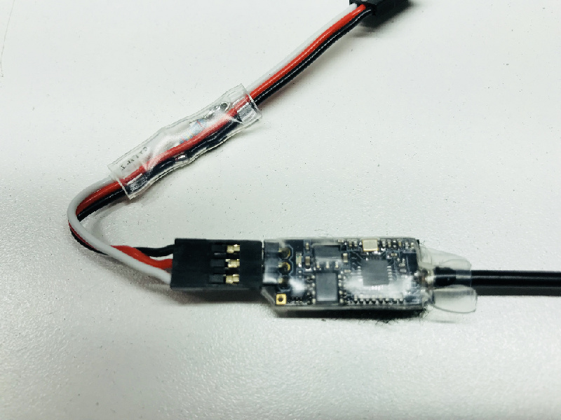
You can add them in line within the cable as well, this way you dont mess with the pc board.
Here is an example with a voltage divider for a receiver on a different implementation:
I just used the old style mission planner ‘live calibration’ and got successful results, w/out the pullups…
But the newer onboard cal failed.
I guess I’ll do a bit more testing before I add them.
My copter is already finished… It’s a tiny 3" prop copter, so no cables to add resistors to. It’ll be a pain to add them at this point (disassembly required), but I guess I should stop whining and just do it if it’s necessary. (The main problem is I’m getting old and can’t see and my hands shake a little… and these electronics keep getting smaller)
It arms! but compass heading is off by 45 degrees… hmm. I’m not positive about the orientation… It’s a csgshop gps, and they’re known to print the xyz indicators incorrectly.
And, now the onboard compass calibration worked!
By the way , I am getting old too 
Most of my work done with theses now:

I’m using external GPS/Mag module so I can put every thing in to GPS enclosure. I just wired two 2.2k standard resistor on some cable soldered behind connector socket. I use 5v to pull-up without divider, acording to stm32 doc FT pins are 5v tolerant, so should be not a problem.
Thanks everyone for your replies.
In the end, I did not need the pull up resistors. Everything calibrated and works successfully.
I managed to destroy my GPS/Compass while trying to tune alt_hold, and the spare I’m using is a different brand w/ a different magnetometer and it works too.
Now I just need to figure out my alt_hold problems… It’s jumpy… Bursts of power up, then down, then up up up until I kill the motors. Unfortunately no logging! But I do have the mission planner logs recorded over telemetry. Anyway, I’ll work on that more later. Stabilize is working great on this little 3" prop quad.
Oh, and thanks for the magnifying goggle recommendation, PPoirier. I need those. I tried to fix the torn off connector (pads missing too) on this GPS, and had to give up… I simply cannot see what I’m doing at that scale.