How to test skid steering (throttle left/throttle right) on ArduPilot

Building a boat with a Matek F405-HDTE, and trying to get the motors and servos wired up. Using the latest software and firmware (dev version of firmware). We were using skid steering, started off with LN298N motor drivers, and recently ditching them for ESC controllers due to lack of support. The ESC drivers work good. The project is a boat with skid steering, the plan is to use servos 1 and 3 as it states:
https://ardupilot.org/rover/docs/rover-motor-and-servo-configuration.html

So I have used ArduPilot enough to know how to get around a bit. I wired up the motors like so:
1 = throttle left
2 = motor 1
3 = throttle right
4 = motor 2

I have stumbled across the revelation that motor 1 = motor A (and 2=B, 3=C, 4=D) in the motor test window. I have also stumbled across the fact that if a servo has been dedicated to another purpose in the config screen, then it is unavailable in the Data: Servo/Relay screen.

If I plug my motors into servo 2/4 (motors 1/A, and 2/B), then they work fine. Is it possible to operate the motors dedicated to throttle left/throttle right from within ArduPilot? We do not have (nor plan to have), a radio/joystick.

Thanks
Throttle Left and Right are the Motor Outputs. If you have them configured on 1&3 as shown connect the Motors to outputs 1&3 and disable those others.

Yes, it works, although Ardupilot motor test is useless, so we keep Motor 1 and Motor 2 configured and wired to servo 2 and 4 so we can swap output wires to do a motor test.

I find it to work fine. With Skid Steer Test Motor C is Left Motor, Test Motor D is Right Motor. Increase the throttle percentage until the wheels spin. Of course connecting to the outputs that Throttle Left and Right are assigned not Motors.

Awfully difficult to Tune the Rover without an RC System. It won’t behave on defaults.

1 Like

This was good. It prompted me to go look at this again. I disabled servo outputs 2/4 and found that Motor 3 was indeed mapped to Throttle Left now, and I found that Motor 4 was mapped to an auxiliary motor on servo 5 that we need to use for another purpose. I mapped this auxiliary motor to Motor 1, and then Motor 4 is now mapped to Throttle Right.

Yes, finding that out, but science fair project has less than 2 weeks left, so it is go time.

How do you do the throttle tune on a skid steer system? I found that the left motor starts spinning at 32% and the right starts spinning at 45%, but MOT_THR_MIN only goes up to 20%, and there is only a single parameter for the whole vehicle, not 1 for each of the 2 sides (left/right).
https://ardupilot.org/rover/docs/rover-motor-and-servo-configuration.html#steering-speed-scaling

I did see the bit about pivot turning:
https://ardupilot.org/rover/docs/rover-tuning-pivot-turns.html#rover-tuning-pivot-turns
WP_PIVOT_ANGLE is already 60
WP_PIVOT_RATE is 60
ATC_STR_ANG_P is 2
ATC_STR_RAT_MAX is 120
ATC_STR_ACC_MAX is 120

Another issue I have, is not knowing what is important for a skid steering boat, and what doesn’t matter as much.

According to the Rover stuff:
Throttle tuning (doesn’t seem like this can be done since I have 2 throttles), but I set MOT_THR_MIN to 20% anyway.
Steering Speed scaling/Tune the Turn Rate Controller - my vehicle doesn’t go fast enough for this to be an issue

https://ardupilot.org/rover/docs/rover-tuning-process.html

I feel that somewhere I should compensate for the Left motor/right motor imbalance somewhere before I start Navigation Tuning, but I am not sure where that would be:
Tune the Navigation Controller: Tuning Navigation — Rover documentation

We started testing in a ditch yesterday, but were challenged by weeds getting caught in our propeller and other challenges. I think our issues are compounded by magnetic interference. Compass calibration never seemed to finish, so I just set it as close as I could to 0 and used the large vehicle calibration.

I plan to go through this page a second time (not sure id the DC motors we are using make it better or worse):
https://ardupilot.org/copter/docs/common-magnetic-interference.html

You will have no fun getting the boat to work, with a deadzone like that and the difference between the motors. Make sure both ESC are calibrated to the same limits (I hope you use two identical ESCs). See if there is any mechanical issue that causes one prop to turn harder than the other one.

How do you calibrate the ESCs? I am using these: https://www.amazon.com/dp/B00JXI3H6Y?psc=1&ref=ppx_yo2ov_dt_b_product_details

I am guessing these ESCs don’t have the ability for calibration like is mentioned in here? The motor configuration is set to Normal, and we are able to get forward as well as reverse.
https://ardupilot.org/rover/docs/rover-motor-and-servo-configuration.html#esc-configuration

I have 4 of those ESCs in an omnirover. They do not have a noticeable deadzone in my case. Did you check if everything is turning freely?

These motors are just regular 12V DC motors. They are fairly rough. One of them spins more freely than the other. I do have a third motor we can try using, but they are these, heavily modified: New Attwood V500 Bilge Pump Model 4204-7 | #170109081

Does it make a difference that we are using a 7.2 Ni-MH RC battery? I know that motors usually operate better with a higher voltage. Although I don’t know what options we would have other than “borrowing” a battery from a UPS or something - I think those are 12V.

Take it from me, until you get speed tuning down per Tuning Speed and Throttle — Rover documentation you’re gonna be nowhere.

Without a RC Tx/Rx that’s gonna be tough. You need to know CRUISE_SPEED and CRUISE_THROTTLE, which requires being able to navigate manually. Why not buy a Flysky FS-6 for about $50 and dispense with all that hassle?

2 Likes

Thanks for the reply - I am not sure I understand why I can’t do what I need to with just ArduPilot - is it just missing controls? What is special about the radio that can’t be done over WiFi? Can’t I just do Fly Here and tweak it to be straight line travel? Or Test All on the motor test page?

Anyway, this morning I twiddled with the motors and got them both to have min throttle at 20% - so way better than it was previously, and they are matched (although I don’t understand why there isn’t Left/Right min throttle entries for the case of skid steering).

I have also since re-wired the entire vehicle, twisting the wires between the ESC and motors, making wires shorter, and re-routing power away from the FC/GPS/Compass. I also put some foil between the FC/WiFi and compass, so maybe all of that will help me calibrate the compass.

Hey - if I add a waypoint to SetServo, the parameter is named PWM - is that in degrees, percent or what? I have a 90 degree servo that I modified the begin/end config so it would do 180 degrees, and in the Data/Servo/Relay page Low Med High, Low is the bottom extreme, Med is the middle, and High is the top extreme. If I set it to Motor 1 and do Test Motor A from the motor test screen, then -100% is the bottom extreme, 0 is the midpoint, and +100% is the top extreme.

Thanks for the reply. Oh, and to answer your question directly, this is a science fair experiment that is due at the end of the month, and the budget is $200, and we are already over budget. And by the time we got any new hardware (and whatever unknown headaches there would be integrating it in), the project would be over, not to mention more integration time would take us away from writing the report.

Plus, if it was me, I would try to understand what the speed/throttle tuning was actually doing, and hack something in to the software that would let me do the same thing without a radio (or make a radio emulator). Seems to me that the Motor Test is my best bet, unless I am really misunderstanding the nature of speed/throttle tuning.

You are. Motor Test is direct PWM passthrough it’s usefulness is limited. Tuning is done in Acro mode or Auto depending on what’s being tuned.

It’s in microseconds.

What functionality has to be demonstrated in this Science Fair?

From:
https://ardupilot.org/rover/docs/rover-tuning-throttle-and-speed.html
I can see it should be possible to perform Desired Speed to Throttle PID Tuning using only ArduPilot without too much issue, but how could I attempt Cruise Throttle and Cruise Speed? Any idea what this does: “Move the aux function switch to the high position for a few seconds and then back down to the low position”? Is this just toggling between two different speeds? Do you then get this message for two different speeds: “Cruise Learned: Thr:XX Speed:YY”?

Great - we can map microseconds directly to an angle. Funny story is that we have ordered three sets of servos already from Amazon. The first ones I didn’t understand the difference between continuous and not (I thought the microseconds would map out to an angle, and not have to worry about rotating back to get to 0 again), but the second 2 didn’t do what they were advertised to do. The second one was supposed to be linear from 800-2200 uSecs, and then rotate continuously from 500-800 in one direction, and 2200-2500 in the other, but it was basically a speed control device (as opposed to position control, like a standard RC servo) through the whole range 800-2200. The latest one I ordered was supposed to be a 270 degree model, and turned out to be 90 degree.

Well, it would be ideal if we can have full functionality, which is a boat that goes to multiple waypoints to collect water samples. We have a water pump that is operated by a relay waypoint that we know works, and a wheel that holds a set of test tubes that we will index with the servo using the SetServo waypoint (hopefully we test this today). Of course a large majority of the grade is likely the report, and writing that will take away from our available time to actually make the thing work… So not in a great place now, but we are making the best of it.

We both really appreciate all of the feedback we have gotten to date in this forum. We would not have gotten very far without it, I am afraid.

Yea, it learns the throttle position for a particular speed. Setting a switch on the Transmitter you don’t have to an Auxiliary chan function does this. This is the easy way. You can drive it and review the log for the throttle position and speed and determine it that way.

Well, you wouldn’t be the 1st on here with a vehicle that barely drives or flys but a paper was still written about it :slightly_smiling_face:

At least setup a Joystick so you can drive this boat while tuning. Assuming you have telemetry.

Is this THR/ThrIn/ThrOut and THR/DesSpeed/Speed? Which ones do I use?

Say ThrOut is 75% and Speed is 1.2 M/S, then what do I do? Just plunk those values into CRUISE_THROTTLE and CRUISE_SPEED?

Thanks

@apcaveman yes. If you drive at 75% throttle and achieve 1.2 m/s then put them into CRUISE_THROTTLE and CRUISE_SPEED. This is the feed forward component in the speed control PID loop. After this you would tune the speed control PID loop like you would any other. Set P,I,D to 0, then increase P until you have some overshoot, then dial it back a bit, then use I to reduce oscillation, etc. If you could test 50% throttle and 25% throttle you would learn about the linearity of the throttle-to-cruise speed response. Since your vehicle is a boat I suspect you will have a large lag (few seconds) between throttle change and speed change.

1 Like

Awesome, this was a great help. We used 80% throttle and got 0.26 m/s.

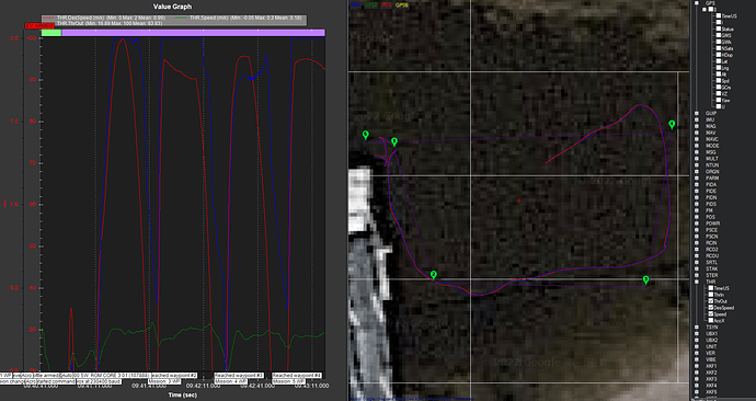
We also ran a box (kind of) waypoint run and gathered some data (without setting the CRUISE_THROTTLE and CRUISE_SPEED). And then of course I had some issues with the log files, so I suspect I lost 3 logs of the 4 runs that we made.

https://www.sunsetsnorkeler.com/SURFACE_BOAT.zip

I see 100% throttle giving you about 0.25 m/s. I recommend you set CRUISE_THROTTLE and CRUISE_SPEED accordingly (perhaps 75% and 0.2?)


It does look like you navigated on AUTO mode from 2->3->4 so congrats!

Yeah, it was pretty awesome. We had better luck at the end of the day, even though the wind kicked up. The morning we found that our mission used Relay 1, to turn on the pump, and should have been Relay 0. We also found that the loiter waypoints don’t do fractions of a second. We needed 0.3 second delay, but the pump would run for at least a second, and overflowed the test tubes. I also realized that one of the waypoints we had for operating the pump had the location for the second waypoint, which is why it angled down so far on the plan that you show in the picture above.

This run we had the CRUISE_THROTTLE at 80% and CRUISE_SPEED at 0.26 m/s. I also turned on logging for GCS_PID_MASK for Throttle, Steering, and I think there was something else too.

https://www.sunsetsnorkeler.com/2022-10-22_16-51-01.bin

Thanks so much for all the help!

1 Like