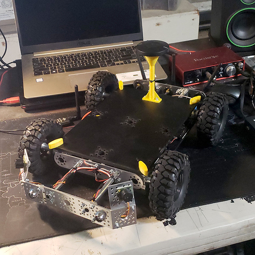
I suggest you follow this thread
Hello, great topic!
I got everything working. The pixhawk/missionplanner displays the distance correctly. But when it exeeds +/-2m it displays 0.13 and will not change anymore. When I restart the arduino pro mini (cut of power and reapply it) it willl display again, only if the distance measured is below +/-2m. In the Benewake GUI it measures a range that exeeds the 2m so the sensor should be fine.
Powering the arduino and TFMINI with an external powersupply at the moment for testing
Any suggestions?
Hello,
You have to find if the problem is on the sensor side or on the FC side.
Can you send static value above 2M just to check if FC reads ok?
Thanks for the fast response.
When I set distance to 300 or more it keeps showing op normal in missionplanner (3 for 300 etc) so the FC part should be fine. The sensor displays distances of 4m+ in the benewake GUI with good accuracy.
In that case you can try reading and outputting on Arduino serial monitor
I could try it out, but for now, I dont know exactly what I changed but it seems to work now. I ran some of the commands for the TFmini again in the GUI
Does Ardupilot 3.6.9 have native support for the TFmini i2c version? If not, is there a workaround with which I can use the TFMini i2c as the only rangefinder on the pixhawk?
I see the new driver has been merged but It’s not on a release yet you have to use Master (beta) release
Hello. I need your help. The fact is that I need to fly 2m above the corn. And when the corn is still small (up to 1m), TF02 measures the distance to the ground and everything is ok. When the corn is large (more than 2m) the leaves are thick, the lidar measures from the leaves and everything is also ok. But there is a period when corn is heterogeneous in the fields, and during one flight the lidar measures from the leaves or from the ground. How to solve this problem? Installing a second lidar will help?
A radar would more appropriate as it bounce on earth, but they are not common at the moment.
Other option would be a surface scan lidar but they are expensive
it has to be in pix mode to work ?
It has to be in binary format to work with with the arduino I2C sketch, not pix
while in bin format
and having uploaded the outdor sketch i wont get corect info to the pixhawk
any help ?
getting 0.2m while crealy io have more than that .
Double check everything and read the thread for similar issues.
I just looked back at the code, you might try changing offset and scaling like this:
uint8_t OffSet = 0 ; //Offset error of the LIDAR
uint8_t Scaling = 1 ; //Benewake outputs in mm, we have to scale to cm
So with 2 TFmini’s going through I2C you can have them both working? I want to have a ROVER stay inside of a hallway or crop row: having one turn left and one turn right when drifting toward wall. Would there be to separate RNGFND_ADDR numbers?
Yes, setting 2 different I2C address and assign the correct orientation is the way to go.
Be aware that having just 2 rangefinder makes wall following difficult because of the unpredictable vehicle orientation errors, better use a scanning lidar and some SLAM estimator
My goal is to run autonomously in crop rows. I need the sensors to make slight corrections towards the waypoint if needed. I am harkening back to the dual Maxbotic solution. If I do have two units, what addresses should be used?
Thank you so much for your quick response!
Remember that this is hexadecimal so you have to multiply by 16 and use the lightware I2C driver that allows for multiple address
I will get two TF Mini’s but I need them both for forward avoidance. One to correct left and one to correct right. (Dual Maxbotic setup for corrections
Need the rover to stay going straight and correct left and right towards the waypoint.
Hi Patrick!
Many thanks for your efforts on getting object avoidance affordable! I have several “old” TFMini and got some newer tf mini plus modules which I want to use for object avoidance on my drone. I want to use all modules with i2c connection. First of all, converting the old serial TFmini modules into i2c devices worked like a charm!
But my problem is I can´t change the i2c adress on the newer Plus modules in i2c mode! They won´t switch back to uart connection, where i could change the i2c adress. But in TFGUI all attempts to communicate with those modules fail. I tried " 5A 04 01 5F 00" for serial mode but had no luck yet…
Anyone of you maybe had the same problem and probably a solution to fix this?
Thanks in advance,
Marcel
