hello, could someone judge me how to install a brushless motor with position sensor, next to the pixhawk and also in the missionpllaner, aunt this possibility?
obs my motor is Brushless with 3 phases, if the sensor of possession and separation, would it be possible to connect it only directly to the esc?
There is documentation on how to use position encoders in the rover documentation.
Brussless motors need an ESC. It should be straightforward to connect the ESC to the flight controller and the Motor to the ESC.
Which exact position encoder are you using? Make? Model? pictures?
1 Like
Here this balance bot
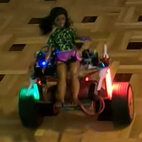
has two low KV motors with sensors, connected to the ESC’s. Since the sensors receive +5V they have compatible levels. I connect two sensors also to the Pixhawk1 as direct/quadrature signals (they are at 120º separation, but that does not seem important). So the three sensors of each motor go to each ESC, and two sensors of each (total four signals) to the Pixhawk1 as direct/quadrature signals.
(The other balance bot has stepper motors with encoders).
1 Like
This Brushless motor is from an impact drill, 18v. I’m using it in my project because it’s easy to find configuration here in the ardopilot community. But I still don’t know if I’m going to be able to make this adaptation, as you can see it has 3 phases, and in the posterior part another 5 wires that must be from the position sensor.
My intention is to make a rover using this engine, I believe that it is not difficult to make a connection with the esc, using the configuration of which.
só pra resaltar, o sensor se trata de um Hall.
This is the only information we have: Wheel Encoders — Rover documentation
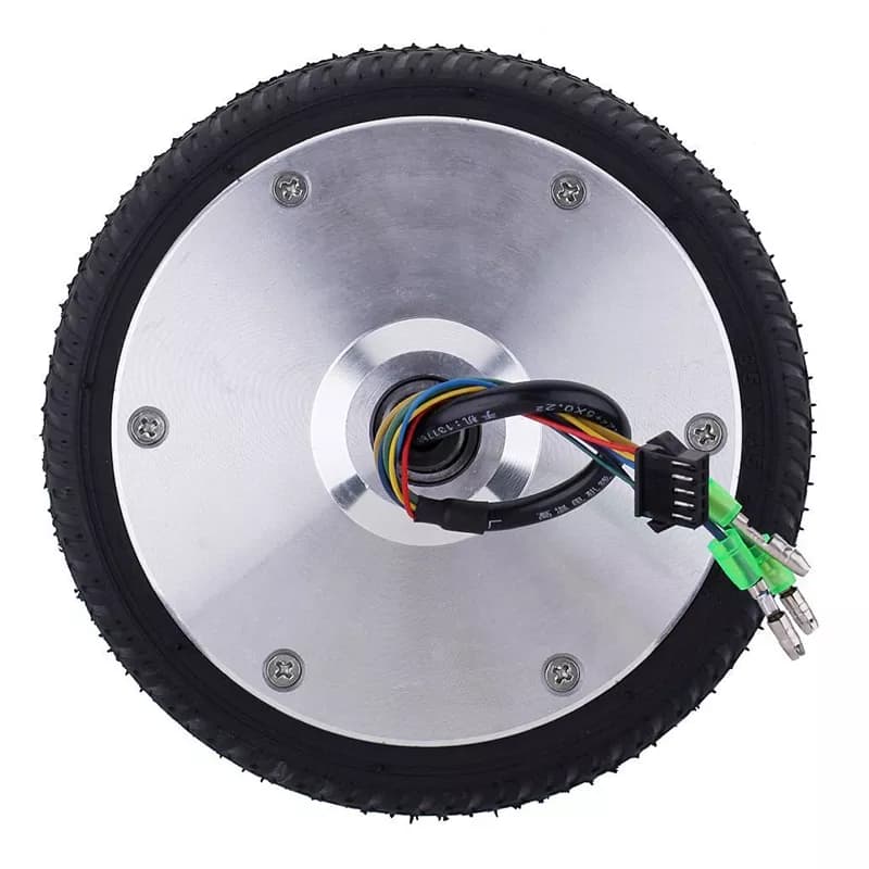
As hoverboard motor+wheel:
- 3 thick wires (brushless motor).
- 5 thin wires in a connector: 2 supply (red/black) + 3 Hall’s.
BTW, connector chosen the wrong way: should be male, since red/black receive supply.
1 Like
@Webillo , é exatamente essa pegada ai, segue essa logica ai mesmo , tem como eu configurar no Pixhawk1, teria como me ajudar com instalação ?, teria algum esquema pra seguir ?
eu ainda não me adaptei a essas configuração de motor sem escovas, eu acho mais facil configurar o com escova mesmo, pois a configuração é mais dinanmica e dá seguir aqui na documentação.
agradeço…

It looks like ArduPilot only supports two channel encoders. Is this correct?
It’s my understanding the three channel encoders on a brushless motor are usually used by the ESC to know which coil to energize. Using only two channels should be able to provide speed information as long as the transition times are averaged. Normal quadrature encoders provide four transitions per encoder cycle but three channel encoders provide six transitions.
When using only two channels of a three channel encoder, the transitions will not be evenly spaced through an encoder cycle.
I don’t know if this non-uniform transition intervals would cause problems with the ArduPilot software. Does anyone here know if using only two of the three channels will be a problem?
Two of the three channels is still enough to monitor the direction and speed of the wheel but the speed calculation will need to be done using at least two transition intervals since the transitions intervals will not be evenly spaced through the encoder cycle.
I still haven’t found the possibility of connecting my hoverborad motor to the Pixhawk, I even have the ESC brushless motor esc, but the hall effect sensors still don’t follow the configuration as it deals with the documentation about the wheel encoders, I would have a more updated possibility , it would be interesting because there is no such information on the internet. appreciate
You might be able to leave one of the Hall effect sensor wires disconnected. I don’t know if ArduPilot will work well when using two of the three sensor wires but it might. The two sensor wires provide enough information for the controller to determine the direction the motor is spinning but I’m not sure if it will control speed well or not.
Do you have the original drill parts? I’m guessing the purple wire is used to power the encoder but it would be nice to check when the wires are temporarily connected to the rest of the drill.
Edit: I’m not sure if the encoder example in the documentation uses an ESC which can be controlled using normal servo pulses. I don’t understand ArduPilot well enough to know which parameters may need to be changed.
1 Like
Pensei também nessa hipótese do fio Roxo ser o do codificador, assim q eu testar de forma segura, estarei comentando aqui. Pois a princípio segue a mesma configuração de um hoverbord, mas a documentação não tem muito detalhe referente. Estou juntando mais informação pra poder fazer um teste mais seguro, para q eu possa assegurar a controladora.
Outra dedução, é que por ser um motor sem escova e está sendo controlado pelo ardopilot por GPS, a documentação trata como se não tivesse tão necessidade pois é papel do GPS,
A princípio os codificador são usados quando não há GPS, que seria já outro caso.
Mas pode usar 100% da tecnologia do motor pra seria eficiente pro meu projeto.
A few things from my experience:
-
Hoverboard motors have a very low kV. I never managed to get them running smoothly with a regular RC ESC (sensored or sensorless)
-
They run fine with an Odrive, VESC, or a reflashed hoverboard controller.
-
The hall sensors need to be connected to the ESC, to get the full benefit of low RPM control and a smooth start.
-
I also tried to use two of the hall sensors as a wheel encoder for ardurover, but even after a lot of trying, I could not get a consistent result. If I remember correctly, the most prominent problem was that the reported distances were different for CW and CCW rotation.
-
There should be a way to calculate a 90° offset quadrature signal from the 120° degree hall sensor signal, but I never tried that.
-
I use AMS 5047d encoders on one of my rovers. To use them with hoverboard wheels, you would have to build a frame to mount them to the outside of the wheels.
After choosing a motor (brushless or brushed (DC)), an appropiate controller must be chosen. After that (MOT_PWM_TYPE):
- The controller may require a RC pulse control signal (1000/1500/2000µs or variants), as common brushless motors.
- The controller may require a PWM control signal (duty cycle 0% to 100%). It is confusing that this is measured/represented as 1000 to 2000 (or chosen range).
This is ideal. Now I am wating to receive parts for assembling a balance bot with two of these motors (size double than those in above video), but from initial experiments this seems promising.
While on above video the balance bot with direct drive and low KV motors was more difficult to tune (lower cog, also lowering ESC’s), and resulted less stable than others with DC motors, the result is acceptable.
Although I think that IRQ handler code for encoder signals can be greatly optimized in timing (with a slight code size saving), I think the code is very solid. These are the WENC signals for the direct drive balance bot on above video:
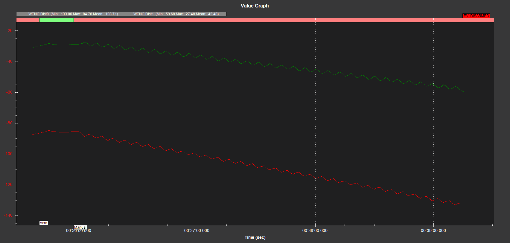
Note the similarity between them, going opposite (the balance bot is pivotting), although the initial offsets and the drift.
As said, I don’t think that the code considers that they should be at 90º (Randy could give a reasoned opinion on this), and as shown connecting two signals at 120º gives acceptable results. However, as said, the other balance bot has stepper motors with encoders, and I found that the encoders gave pulse/direction instead of direct/quadrature signals (not supported; see WENC_TYPE/WENC2_TYPE), so I inserted an Arduino for doing the conversion (hanging at Ken’s back, with red/green signaling leds). The same can be done for 120º/90º conversion.
Here is a first assembly:

Still some parts to add, and improve setup for a faster one, since it is incredibly stable, and test on a real circuit as this.
For what it’s worth I am getting good low-speed performance (full torque down to 0 RPM and smooth start) from BLDC motors (from https://www.freerchobby.cc/) without sensors (i.e. in sensorless mode) using Vedder’s VESC controllers. This on both 50kv and 140kv motors (not that it matters).
I wasn’t able to get the ODrives working in RC(PPM) mode, likely due to operator error or operator inexperience…
I wrote some code using a hall sensor example and a quadrature encoder emulator and hacked it together, i only checked if it compiled but i never actually tested it.
https://github.com/geofrancis/hall-sensor-to-Quadrature-encoder-adapter.
The stock hoverboard controllers should be ideal for a balance bot, it’s essentially what they are designed to do.