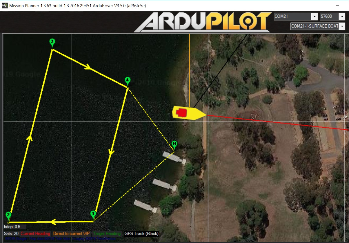
During the Canberra developers meeting a few of us (Leonard, Yamaguchi-san, Ebin and I) tested a high speed RC boat provided by HobbyKing and HolyBro. These are the details of the setup:
None of us had had much experience with high speed boats so we discovered quite a few things:
it’s important to remember to plug the little hole on the back left side of the boat or it will fill up with water in about 10min
the boat begins to plane at about 4m/s and becomes more maneuverable than at lower speed. We should probably add a new parameter to Rover to allow the user to specify this speed and then we should modify the “lane based speed control” so that it never attempts to reduce speed below this when maneuvering around waypoints
when attempting to accelerate quickly cavitation was very noticeable. Reducing the default maximum acceleration (ATC_ACCEL_MAX) actually led to the vehicle accelerating more quickly because cavitation was avoided.
the boat leans over when accelerating and can turn right more quickly than it can turn left. This may be partially because the rudder wasn’t trimmed perfectly but it may also be because the thrust provided by the motor naturally leads to an opposite rotation of the whole frame. I’m not exactly sure how to solve the problem but perhaps in the future we will try with a frame which has two motors spinning in opposite directions.
By the way, to keep the electronics dry I cut a rectangular hole about 3cm x 10cm on the underside of the removable cover (which stretches from the blacked out windscreen at the front to the black hook-like knob at the back), then inserted the RC receiver, flight controller, GPS and telemetry radio, attaching them using 3M double sided adhesive foam. The 3cm x 10cm hole was then closed using duct tape. The battery power module was left in the main open area of the frame but partially protected from getting wet using a red balloon that came with the set (intended for use with the RC receiver).
Hi Randy,
Was really great to read this.
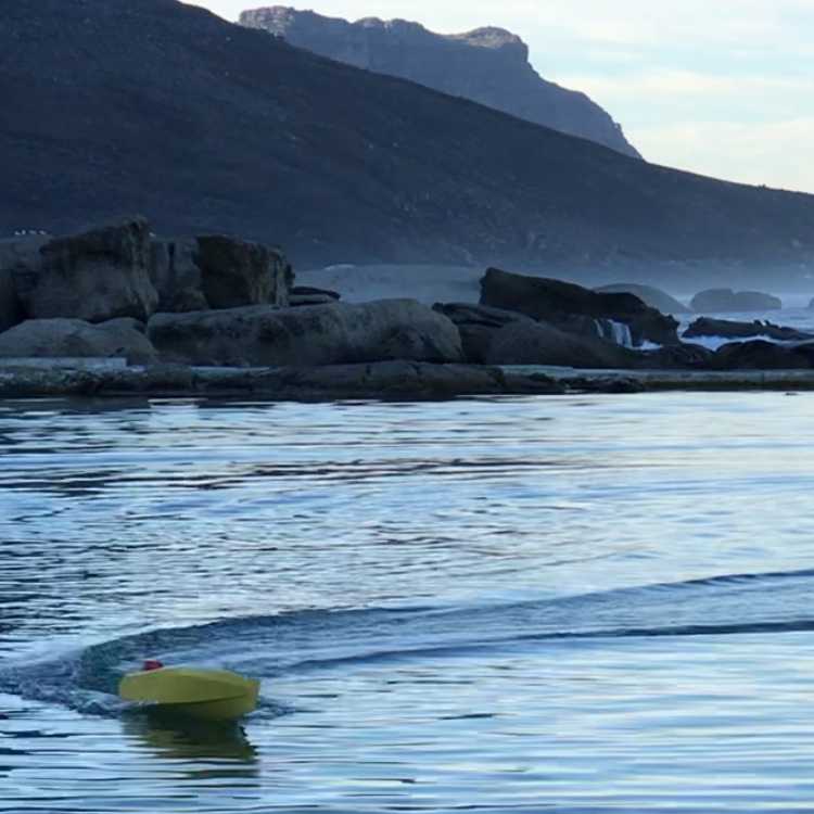
I also have a high speed boat and have been doing some autopiloting similar to this.
Yes the roll angle of the boat is affected by the props and most boats have a tendency to roll more to one side than the other in turns.
I Have also found modifying the maximum acceleration helps… I blew the gearing in a couple of drive units this way…
I’d be very grateful if you continue experimenting with this setup… always good to see solutions others have come up with. If you like I can post some video and findings here, too
More videos would be great to see. I suspect this boat will become one of my standard test vehicles because it’s high speed is useful for testing the limits of our controllers and it’s also just good fun!
If I did replace the boat, I’d probably replace it with one with two motors/propellers because that would get rid of the lean and also some skid-steering (using the motors to improve turning especially at low speed). I don’t have any immediately plans for that though.
It would be nice to be able to proactively shift a weight in the boat to the left or right to counteract the lean from the motor’s torque - maybe by pumping water from one side to the other or maybe with a weight on a servo but I don’t know of any readily available hardware out there to support this… and I’m not too keen on a DIY solution because I worry that it’s too niche for most of the community to adopt.
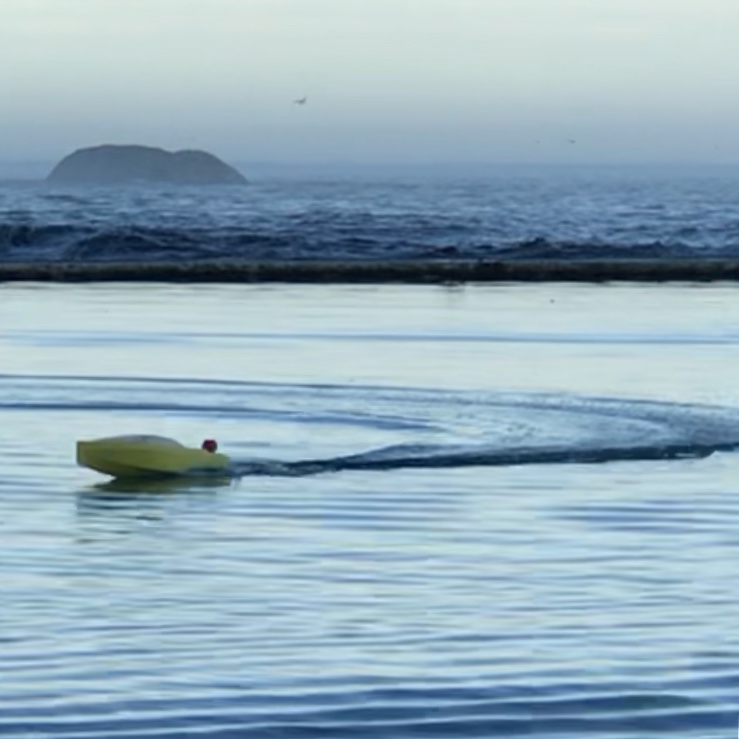
My initial model is 1.25m long, and I have lead ballast to move the mass around. At the moment I am only pushing it to around 7-8m/s.
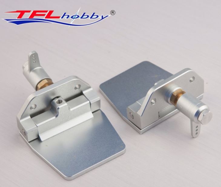
What I was planning on trying to achieve was to have two active ‘trim tabs’ on the transom of the boat. These are essentially little flaps that get pushed down into the wake coming off the back of the boat. they can create a rolling moment to either side. It would be very cool to be able to play with this:
It would help correct any propellor induced rolling
Adjust how much the vessel rolls during manoeuvres to improve turning circles and stability in turns
Keep it ‘flat’ when going over waves
Help adjust how much the bow of the boat rises at different speeds and assist the boat getting onto the plane.
All of this would of course be active and you could create a cool algorithm which tells the flaps to push into the water different amounts when doing different things and at different speeds.
In my mind the basics wouldn’t be too difficult… they are essentially like the wing flaps on an aircraft? Two servos added to the boat, one for each trim tab. (May need a bit of leverage/mechanical advantage for them to be strong enough.)
Would love to hear your thoughts… In my mind this has a lot more scope than simply adding an extra engine?
They really make a huge difference on full size vessels, and I think if the servo response if good enough for the steering, or for plane flaps, then it would also be good enough for this application too.
Randy, there is also a system called ‘Humphree interceptors’ for full size boats that have a lot of applications, whether actively steering the boat for power catamarans or for trim and stabilisation at speed for powerboats. Similar to trim tabs but with a different mechanism.
It would be great to play around with this at different speeds and in different autopilot scenarios!!
i think we could add a roll and pitch PID and do a elevon mix. Harder bit is deciding what we should do with it. I guess as a starting point you could just target 0 roll and pitch. Maybe doing something like planes rudder mixing for roll on turns.
This trim idea sounds really good especially because it seems like this is what the full-sized boats are doing.
Regarding our mission, we do have a motto at least which is Versatile, Trusted, Open and a RoadMap (in the process of being updated now that we’ve had the annual developer un-conference) and I’m planning to keep improving Rover/Boat over the next year and it looks like others are too. I would very much like it if AP was used all over the world for all sort of different boats both for hobby and professional use.
Have a look at this video from around 1minute in. This outlines one stabilisation method in use on full size boats. https://www.youtube.com/watch?v=UlB67fa567c
Bear in mind this is a dynamic system, so boatspeed is required… it will not stabilise when at rest and unlikely to be effective when loitering. But this is also the case with any trim tab system. If you want stabilisation at rest, then a gyroscopic unit can be used, like the Seakeeper products… but I doubt this is the route you want to take.
It would be interesting to explore both the ‘interceptor’ construction, and the simpler version (a hinged a flap off the back of the boat). I think from a system point of view there is no difference… either method requires 2 servos to actuate the interceptor or flap on each side of the vessel. For maximum effectiveness you want these positioned as wide as possible on the transom.
I’m very happy to hear you are planning to improve and update the Rover software. Let me see if I can upload some pictures of my first 1.25m model at 7m/s. It is a custom built hull, internal structure and skins from 1mm ply, there is around 3kg of lead ballast on board. You can see a GoPro unit on the back which is filming the wake. At the moment I have a single 43mm propellor driving the boat. I will soon test a new hull with twin propellors.
Peter, I can test the code on one of the boats I have (see above pics).
Let me know what hardware you’d like me to get. I can 3d print some trim tabs and sort out the mountings onto servos.
It will take me 2-3 weeks to get to, but I’ll happily do it
Fantastic.
I’ll read up on some of the hydrodynamics of the tabs, and also do some basic maths to see what kind of loads they’ll deal with which will allow to size the servos correctly.
With the current boat I have simply an output for motor and an output for steering servo.
I would guess you’ll just use two more outputs on the flight controller?
Out of interest, will you allow the outputs to be modified, or scaled?
And could we create an algorithm which modifies the output depending on:
instantaneous craft pitch and roll (to seek a fixed value for either)
instantaneous steering input
instantaneous throttle input
That way we can use the tabs to modify the desired roll angle during turns and also modify the effect of the tabs as speed varies.
PID loop sounds great. Roll will typically seek 0 when steering is neutral.
But for good maneuvering setting the desired value is critical.
For a catamaran it’s likely you’ll want to stay close to 0 during turns regardless of speed so thats an easy one.
But for a monohull, the amount of roll in a turn usually depends on what ‘feels’ comfortable or safe when on a boat. Too flat and you feel like you’re being thrown out of boat, and too steep and the boat can spin out.
The roll affects the g forces experienced, as well as the turn radius and how much speed can be carried through the turn. It also affects how much throttle you need to complete the turn. So, for a racing boat, this would be really handy to optimize, and it will be different for each boat depending on type and number of props, and the ‘V’ of the hullform.
It would be nice to make the desired roll a function of both steering and throttle inputs:
Steerage because that will indicate how sharp a turn is being executed
Throttle because the desired roll angle in a turn also decreases with increased speed.
Regarding pitch… well the boat will usually pitch up a lot initially as it gets onto the plane, and then once there it will settle down. Ideally this is a function of speed, but for now if you could manually set the target (to say, 2-4 degrees bow up) that would be just fine. Bear in mind that the trim tabs can only create a bow down moment. So if the boats center of mass is too far forward, then it may not even reach these pitch values and the trim tabs wont do anything. (In his case the pilot can simply adjust the CoM further aft to increase the natural pitch of the boat at speed).
Lastly, I guess you could mix the two so that the roll outputs are simply added to the pitch outputs, and those mixed values are what the servos execute…?
I hadn’t thought about G forces, I guess if we wanted to be fancy we could target the gravitational vector to be down in the boat frame. The analogy would be a bicycle leaning in to the corners. I think plane has something like this for do in coordinated turns, maybe we could borrow the code.
Yeah, I was planning to do this, in plane terms its a elevon mix.
I think the lateral acceleration would be a great way to tune the roll of the vessel for a given steering input.
And if we could manually set to seek 0.1g’s into or out of the turn that would also be really useful…
I think this has the benefit of allowing you to still turn very sharply and experience a ‘high g’ turn whilst maintaining control and directional stability. The roll control should mean that the g’s experienced are purely acting ‘vertically’ in the boat reference.