Hi! Could you please tell me where I can solder the lidar? I searched Google, but never found it (
It would help if you provided more information about the flight controller and the lidar.
Does the lidar communicate via UART, I2C or some other method?
3 Likes
I’m sorry, I forgot to mention this because I was desperate.
FC - speedybee v4
Lidar - MicoAir MTF-01
Yes, I saw this link but since I’m a newbie I didn’t really understand what to do with this information
It’s a regular UART/serial connection. Vin/Gnd should be clear, Rx goes to Tx, and Tx goes to Rx of any available serial port.
1 Like
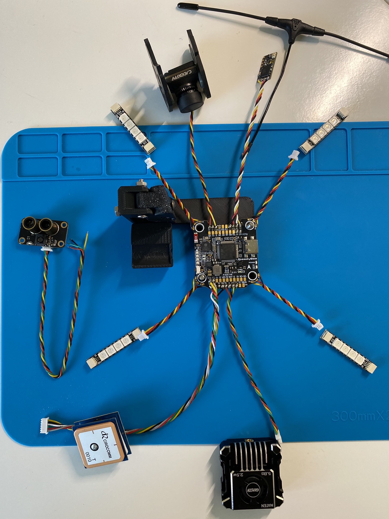
Yes, I understand that. I even found the pinout on Google. But I don’t see where I can solder it ( Can you show me on my photo attached to my first post. I will be very grateful
Top-left in the image, right below where the camera is soldered, there are the pads R3 and T3. Those are Rx and Tx for UART3 (Serial3)
1 Like
That’s great! Thank you a lot! Can you tell me where else to solder the ground and power? )
If you want to keep the lidar wires close together I’d go for the “5V” and “G” pad that you already soldered the camera to.
If you don’t want to double use soldering pads I’d go for the “5V” and “G” pads next to the GPS connection.
2 Likes
Thank you for your help!!! ![]()
1 Like