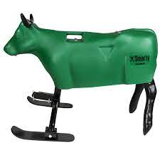
Hi folks. I was wondering if so one can help me out with what i need to get started. I’m building a self driving roping dummy for training rope horses. I have purchased 2 golf cart type motors wanting to build a zero turn mower type setup, 1 motor driving a wheel on one side and the other driving the other side. The motor controllers i have are in the control format :
(0-5k, 5k-0, E-Z-GO ITS, Club Cart 5k-0 3
Wire (MCOR), 0-5v, Taylor Dunn 6v-10.5v,
USB Throttle, Yamaha 0-1k, Absoute Mode)
Want it to self drive (gps) and off remote control. Is it possible for someone to list the components i need and where i could purchase them in Canada?
Some features i would like.
Shut down switch (micro switch on machine)
Obstacle avoidance (stop machine)
Planned route
You’ll need flight controller. (cow controller?) Don’t know what the budget is, but a simple one would work:
And GPS
You will want some kind of RC link. Doesn’t need to be fancy, but you’ll need it to get tuned and at some point you’ll want to just move it around. This is as basic as it comes. No telemetry or data back.
To plan routes you may want to have access and control from a computer. A simple set of telemetry radios will do that. Then you can update routes or make adjustments from a computer while the steer is out, and you don’t have to bring it back to the chute.
I can’t help with motor controllers for something that size, but others here can. All the links I posted are here in Canada.
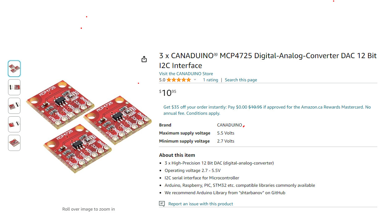
Those (golf cart motor?) controllers don’t appear to take an RC signal as input. You might be able to pretty easily use a microcontroller (Arduino or similar with onboard DAC) to take the RC signals from ArduPilot’s typical/default outputs and convert it to analog 0-5V out.
I have already ordered the items that were mentioned! Is the 0-5 not a pwm in put? Attached is the motor controller specs. DOC112-003-B_SPEC-SR.pdf (141.4 KB)
None of those appear to be PWM nor RC PPM (often also referred to as PWM, though semantically incorrect). 0-5V is an analog voltage range, which would be easy to duplicate with a microcontroller that features a DAC.
Pretty sure you can control brushed motors with PWM . See Brushed Motors — Rover documentation Look at “Brushed with relay” and “Brushed BiPolar” motor drivers
I reckon golf cart motors might be a little slow though. they tend to be geared to go at slow walking pace
Not exactly. You’d need to write simple microcontroller firmware (or perhaps Lua script) to convert RC to the required I2C protocol required by that breakout board.
I freelance writing such code, but I’m afraid I can’t take on your project, as my time is extremely limited right now.
Raw PWM such as that described in the post above won’t work well with your chosen controllers because most autopilots only output 3.3 volts on those pins, and a synthetic analog output created using duty cycle based PWM may not play well with your hardware in the first place. You’d need entirely different hardware (motor controllers) to use Skyscraper’s suggested signal chain.
Quick Amazon search turns this up, which would work on the 0-10V protocol on your selected controller. You’d use the brushed DC output autopilot configuration, as previously mentioned.
EDIT: On second glance, maybe your controller doesn’t have a 0-10V option. But this type of board is moving in the right direction to avoid a custom software solution.
Would be interesting to know how your controller is reversed. Usually it’s a separate pin that needs some fixed voltage (or ground) to trigger the reverse function. The brushed motor config in ArduPilot supports that type of architecture and could potentially control a relay or MOSFET as needed to provide that signal.
Yes. Looks like it might work. Seems to state a max input frequency of 3 kHz, so you will need to set that option in your MOT_PWM_FREQ parameter Complete Parameter List — Rover documentation
There is a manual here that looks like it might be worth a read ( Maybe there is one for your exact controller though). There is a mention of a 0-5V option in there. and some wiring diagrams.
Probably best to do some through testing with a voltmeter before letting your cow loose on the world
Hey folks. I have bought all these things. I have remote working telemetry working. But i can’t get the gps to work in Ardupilot. H743-WLITE M10Q-5883 wired onto tx and rx 2. What are all the settings in Mission planer i have to set and to what? Sorry im not very smart on this stuff and internet search’s are coming up dry.