TX2/RX2 is Serial port 3.
SERIAL3_PROTOCOL,5
SERIAL3_BAUD, 38
And yes, make sure the TX on the GPS goes to RX on the FC, and vice versa.
TX2/RX2 is Serial port 3.
SERIAL3_PROTOCOL,5
SERIAL3_BAUD, 38
And yes, make sure the TX on the GPS goes to RX on the FC, and vice versa.
the serial 3 are set to this and i have rx to tx i have tried both ways. Still didn’t work
What pin are you connected to for power? If it’s labled 5V then it only works by battery. If it’s 4v5 then it will work by battery or USB.
What message are you seeing in Mission Planner? No GPS or GPS: No Fix?
Its on a 4.5 pin. its powered up green light flashing on gps. Mission planner says GPS:No GPS
Attached is a picture of
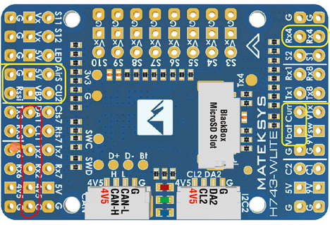
the pins on the board i have gps wired too, circled in red.
how many serial ports are set to GPS, make sure it’s only the serial port you are using for the GPS that is set to GPS.
is the compass working? you should see mag data
can you share your parameters ?
I have the same hardware and that’s how I’ve wired it. I’ll echo what @geofrancis suggested: Make sure there is only one serial port set to GPS. Changes to serial ports only take effect after a power cycle or reboot.
Double check the wiring. Did you solder pins to the board or are you wiring directly to the board? If you soldered pins, maybe do a continuity check on the pins on the GPS wire harness.
Thanks it was serial 4 gps on after that its working.
Good day. I’m playing around with my project. Testing before hooking up motor or building the actual steer. I’m testing using a multi meter I’ll attach some pictures. Throttle 0, throttle about 50%, and throttle 100%. Looking for 0-5v for the motor controller but with multi meter is .19 to .46v what am I doing wrong?
I have no experience with those controllers but I’ll take a stab: Have you made any adjustments to the “output Voltage Adjustment Potentiometer”? If it’s anything like some of the off-shore DC Buck converters I’ve purchased in the past, I’ve needed to turn that adjustment screw in a lot of turns to get the output voltage to come up.
have you configured the flight controller output to brushed with relay?
Not sure which setting this is?
I did yes not much change still stayed in the .v
Set MOT_PWM_TYPE = 3 for “BrushedWithRelay”
https://ardupilot.org/rover/docs/rover-motor-and-servo-configuration.html
So i setup my motor and motor controller on the floor. Wired according to instruction that come with motor controller. Thinking that it needed a 0-5v input. First started it was spinning with throttle down would stop when throttle up, switched the 2 input wires then it was opposite. Sped up slow down not sure of rpm. But after a power cycle and even flight controller powered down motor would spin on its own while still wired to flight controller. Unhook wires it stops.
I tested input wires and they have 4.4v on them (a lead on each wire with multi meter)
I think a need a device to regulate that 0-5v from motor controller with the pwm from flight controller, does this sound right? Or even possible?
J4 has 4.6v coming from motor controler. When J5 sees voltage Motor starts to spin, 4.6v is full speed (i think).
When using pwm to 0-5 converter wired one way voltage would go over the 5v and trip out motor controller with its built in protection.
So this pwm to 0-5v will not work for this application as it puts out its own voltage.
I need a device that can regulate the motor contollers voltage from 0-5v.
There are other possible setting for throttle control also
1 Green LED Flash = 0-5k throttle
2 Green LED Flash = 5K-0 throttle
3 Green LED Flash = 0-5V throttle
4 Green LED Flash = EZGO ITS throttle
5 Green LED Flash = 0-1k Yamaha throttle
6 Green LED Flash = 6 to 10.5 Taylor Dunn throttle
7 Green LED Flash = Club Car 5k-0 3 wire throttle
8 Green LED Flash = Reserved
9 Green LED Flash = Pump
10 Green LED Flash = USB Throttle
11 Green LED Flash = Absolute Throttle
Do anyone have an ideas?
The issue is simply that controller was never designed to be controlled by a microcontroller, its designed to have an analogue throttle connected for someone to operate. you really want to be using a DC motor controller designed for RC control.
So i took the ground pin of the 0-5v output of the 3.3 to 0-5v converter to the ground of the battery/motor controller. Then to the positive of to the J5 pin of the motor controller. With the remote i can now give a 0-5v to the motor controller it stops and goes up and down in speed.
Does anyone see a problem doing it this way??
thats fine, you now need to setup the relay output to control reverse.


