Hello there !
As the summer comes to an end so does my GSOC project, this will be my second post regarding the walking robot support for ardupilot .This will also be my final submission for gsoc final evaluation containing links to my work over the summer.
Continuing from my initial post where I discussed how I plan to execute the project , well as expected there were some changes to the initially proposed setup.
Over the period of gsoc I was able to add basic support for a walking robot with manual mode
Working video:
Lua scripting :
The major changes being the decision to add walking robots low level controller through the scripting engine using lua scripts. This was decided as a measure to give the user access to the kinematics and easier way for the user to do modification if they decide to use a different frame.This could be a very good example of what can be achieved with AP_scripting.
The walking robot by nature is very complex , for it to walk with stability it needs 12 servo angles calculated (quadruped) and this can be almost impossible to test without a graphical representation . As discussed in my previous post, pybullet was planned to be used , but pybullet had to talk with the ardupilot flight stack , this was done with the ardupilot JSON backend. During initial stages of testing, pybullet was via the pyrobolearn framework
Due to its support for multiple robot models and ease of use , but later it was decided to use pybullet standalone due to some shortcomings of pyrobolearn like difficulty faced in installation and that it comes with a lot of useless packages for our use case.
The next step was to built the robot joint by joint with an Unified Robotic Description Format (URDF) , this was build with the exact dimensions of the robot frame used
The math :
Now that the simulation environment was set up it was time to build a mathematical model to control each joint.A basic idea of how the kinematics work is explained in my initial blog .The kinematics model was based on the Denavit-Hartenberg convention .
The paper explains the inverse kinematics of a 8DOF quadruped that was further developed to suit our need of a 12 DOF model which has 3 joints in each leg.
For the ease of testing I tested these equations with a python script on pybullet , once I was sure the kinematics model was able to control the roll pitch and yaw of the body and the position of each leg preciesly I was convinced I could move on to a work on the higher level of control. In the ardupilot flight stack this is done by the help of the lua script
The plumbing between ardupilot main code and lua scripts :
With the kinematics setup now the model required control information as input so it could produce the subsequent joint angles.
This could be done in multiple ways , initially the get_output_scaled( ) function from the already existing main code was used , this function was added to the lua bindings
With this function returning values such as throttle and steering I was able to control and move the robot in the simulation environment . but soon we realised this wasn’t the ideal way to control the robot . So a new function was added for the sole purpose of sending control inputs to scripting.
This code was a part of a bigger PR but to ease the integration it was cherry picked by @rmackay9 to smaller PR’s with some modifications.
Hardware :
It’s almost a given that anything that works well on simulation will not work the same way on a real robot, same was the case with the walking robot . It took hours of tuning and troubleshooting before the hardware could successfully replicate the simulation.
Some of the other issues faced was the lack of torque from the servos , this was due to the lack of current given to the servos via the 5A UBEC , this is sorted immediately after switching to an 8A UBEC.
Also it is important to make sure the servo rails of the flight controller used should be rated for higher voltage (6V) .
There was also an issue of the servo horns having an offset , what this means is that at the same pwm value all the servos horns might not be aligned. This can be fixed with a servo tester.How to fix servo center
The walking gait :
After testing the roll pitch yaw of the robot on the hardware it was time to make it walk ,this required more information. This is generated by a gait generator .
I have gone with a pretty standard gait generator by kurtE to support future gaits. New gaits can be added by simply adding new gait parameters.
The gaits can be further improved by adding support for center of mass correction for a more stable walk. This will reduce the body shift which is seen in the current version.
Time delay between gaits:
As the servos used in this robot have no form of feedback this raised the issue of servo state estimation.Due to this the gaits did not know if the previous leg motion has been completed or not . This is solved by producing an imaginary servo feedback using an ideal case of 60 degrees per 0.24 sec for the HS-645MG servo.
Roll and pitch controller :
The attitude controller is planned to be added in the acro and auto modes. Although the code is fairly complete it is still not tested. With some work it will soon be added. Once the controller is in place it will reduce the body deviations while walking making it more stable and solve the issue of the rear legs sliding off the ground during walks as seen in the video .
An issue list has been put together of which some have already been solved.
Future improvements :
Add center of mass calculations for the gaits generator
Test the attitude controller for roll and pitch
Test auto,acro,RTL modes on hardware
Add control for body X and body Y offsets
Concluding Remarks
These last three months of work with Ardupilot has been an amazing learning experience for me. The amount of attention to detail and strict coding practices followed in ardupilot has taught me a lot.
I can not thank @rmackay9 and @khancyr enough for the help and mentoring during the time.Also thanks to @tridge2 for all the help and advice.
I really look forward to continue working with this team and taking the Walking robot project even further.
I’ll probably re-create this setup myself in the coming months. Longer term I hope we see a really big creepy walking robot using ArduPilot. I think that’d be really fun and a great video.
Great work! Could you please explain why you choose to modify hexapod frame?
And could you change the link to gait generator repo to point directly to the code
Kudos to @rmackay9 and @khancyr for mentoring on this method of developping the Companion Computer logic within FC using LUA, it really opens door to a new way of thinking about implementing complementary control.
Why LUA, what are the benefits of LUA? Years ago predecessor of PyTorch, Torch had interface in LUA but they droped it redesigning PyTorch (probably first commit was to add Py- to name
If we could run Python on the STM32 board we would do it but we can’t.
In this case, it will prevent us to have to add 1000 parameters to support each type of walker configurations … So it is pretty convenient for some output mixing or simple script that you don’t need to be written in hard into the firmware
Yes, I understand the benefits of dynamically loaded scripts. I’m not into STM32, so now I understand the motivation. Nevertheless, I’m probably not the only one here that have to learn this niche language
I am very interested in this project and think to build this.
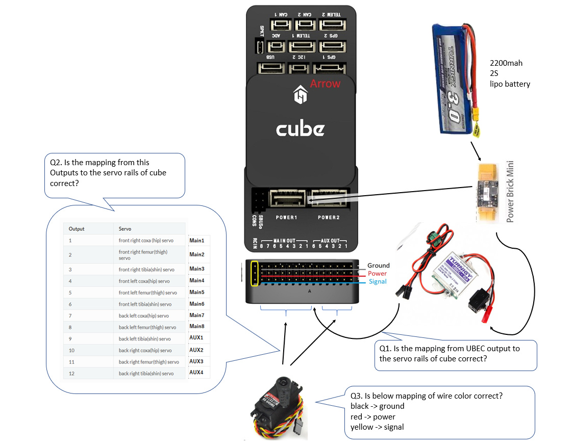
However, due to my lack of assembly experience, I could not understand about wiring of servos and UBEC in the contents of the Wiki well. https://ardupilot.org/rover/docs/walking-robots.html
Could you please answer the questions as I attached an image about wiring and questions?
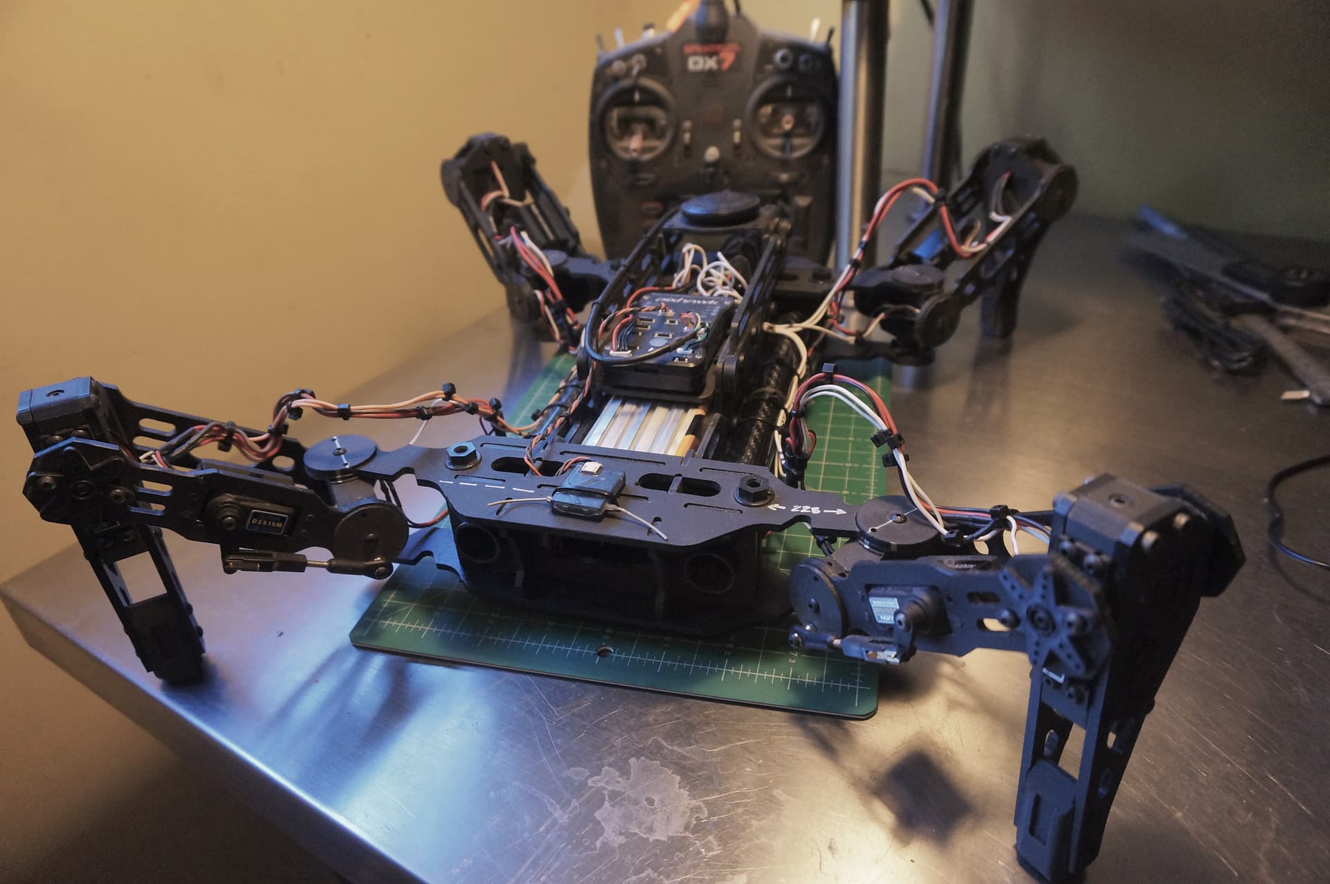
Hey everybody,
I just recently realized that support had been provided for walking robots so I got started on this design. All the “joints” and feet are 3D printed CF (carbon fiber) PLA. The structural elements are .125" Kydex, machined on a CNC machine. Carbon fiber tubes join the front and rear assemblies.
I am pretty sure the frame and everything is in order, but I am unclear about what requires editing in the script prior to loading the script onto the vehicle.
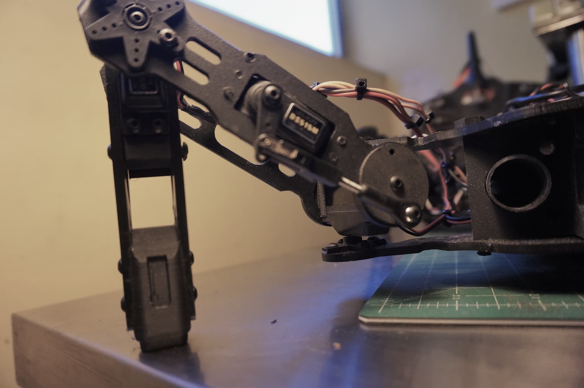
I set the length and width of the frame as well as the distance between servos and servo to foot distance. I set COXA_LEN to 0 given the two servos actuate around a central point (picture 2).
For X,Y, and Yaw travel, would a 0 value for target gate length allow for movement.
Setting gate_type (0 or 1) Does this apply the appropriate params per gate_type from the definitions that follow in the script.
I appreciate any clarification anyone may be able to provide.
I have very little experience on the code side of things so please excuse the lack of accuracy in describing my problem.
Thanks,
Sean
I am having trouble with allocated size for quadraped.lua to run on the pixhawk 1 I am using. Starting at the default setting , I get a message that more memory must be allocated. Going up 25% at a time, I get the same message , until I get the message that it is unable to allocate memory.
I tried formatting another microSD 32GB (fat32) thinking this might increase the amount of space that could be allocated. It doesn’t.
I am only running the quadraped script.
Any thoughts would be appreciated.
Best,
Sean