Full Size Boat Minn Kota Powerdrive Setup

Hi all - I’m new here, take it easy on me :slight_smile:

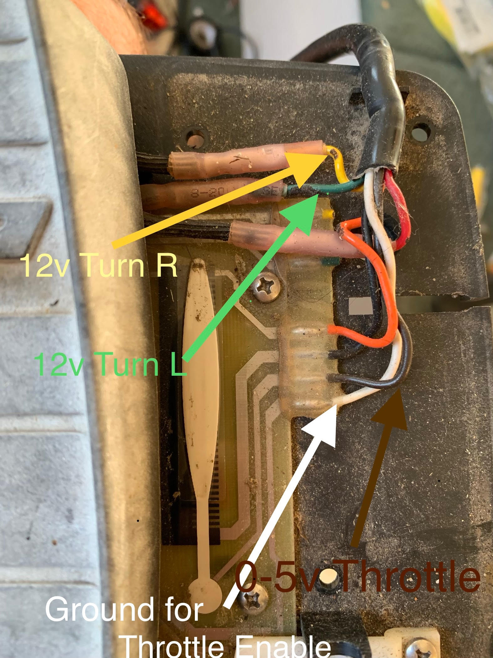
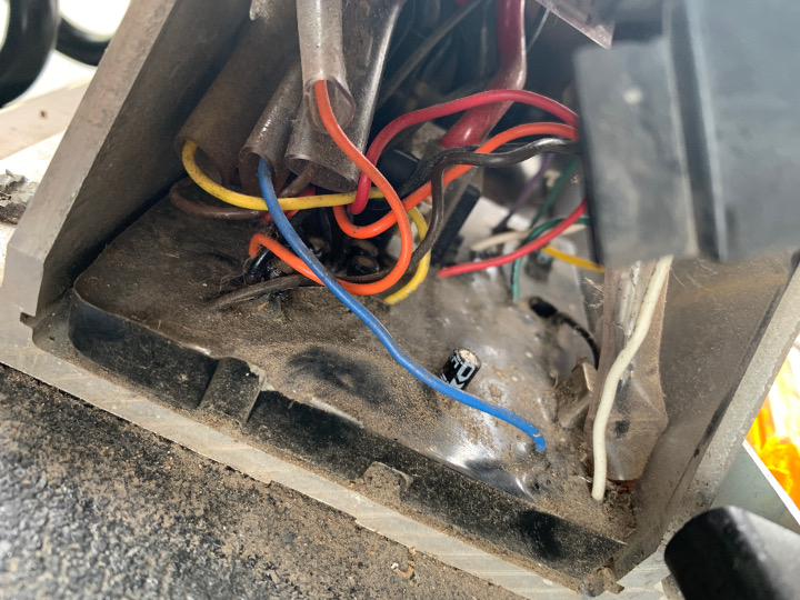
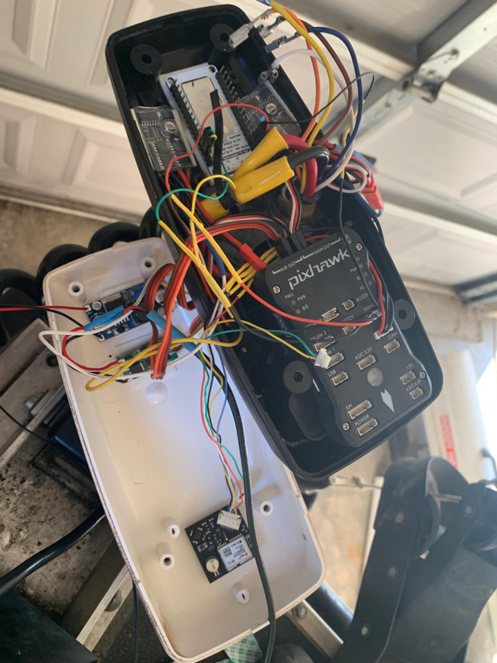
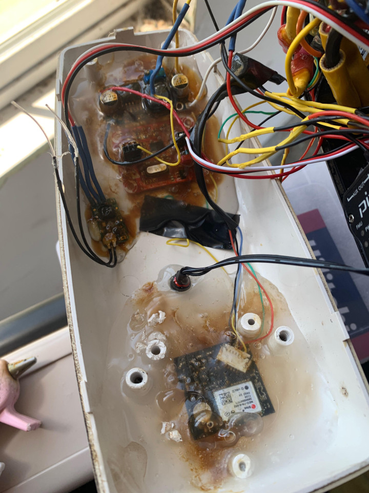
I’ve decided to try to use a pixhawk to upgrade my Minn Kota bow mount trolling motor on an 18’ fishing boat as a diy (fun project) solution to their commercial iPilot product. All of the hardware reverse engineering is done and the pixhawk is able to control the steering and thrust on the trolling motor. I’ll try to put up a post documenting how I did it once everything is working properly to help others since it’s been a fun project so far.

As I’ve been working on tuning, I’ve quickly run into one pretty big issue. Since the pixhawk is mounted inside the top pod on the trolling motor, “ground steering” directly controls the heading of the motor, regardless of throttle or vehicle speed. Admittedly I’ve not done much tuning, but I’m having an issue finding any PID or FF settings that will “lock on” to a compass heading in acro mode. What typically happens is that as the back of the boat swings one direction, the motor will stay pointed at the set heading within 1-2 degrees(good), but then when the boat swings the other way, the pixhawk will allow the motor to stray off heading 20-30 degrees before any correction is made (bad). Does anyone have any suggestions on what PID settings might be required in my situation where the heading is directly controlled by the steering motor? I’m not sure that any PID logic is even required for low level steering in this situation. I’m away from the boat right now, but I could send a log file later.

2 Likes

Pixhawk is designed to be placed in the center of the vehicle:
http://ardupilot.org/rover/docs/common-mounting-the-flight-controller.html

I think you need to mount Pixhawk off the motor, and on the boat near the center, since the motor moves. You are constantly moving the motor but the boat is the “frame”. So Pixhawk has no idea what is happening to the boat. The way process control works is to make a guess what the controller must do to move the vehicle to the desired new location. Then check and see where it ended up. But it does know about the boats position only the motors position.

1 Like

If I’m reading this properly you have the controller on top of a motor that pivots? That will not work.

1 Like

I’m not concerned about the actual boat heading or velocity. For all intensive purposes we should be able to assume that the motor is the “vehicle” and the forces that the boat exerts on the motor are no different than what a wind or current do to any other craft.

Among the myriad of issues that would develop if the controller were removed from the motor is that there is no good way of obtaining thruster position feedback, and given the large lag in acceleration response we would just be increasing the number of open issues to solve.

I’m convinced this setup will work (provided the proper software and configuration), as there are 2 commercial solutions that exist with the exact mounting configuration I’m using. It is however possible that Ardupilot is not able to provide the control needed for this capability, but I doubt it.

Again, breaking this issue down into smaller chuncks, currently I’m not worried about navigation. I just want the controller to keep the motor pointed in the same heading. Don’t worry about the boat as a whole.

Use steering mode. That will keep the motor on the same heading.

AS far as the PID’s go post a parameter file and I may have some suggestions to get things working better. I think PID logic is required for what you are trying to do. FF might be way to low as well as the P and I need a bit of tweaking.

Thanks David!

I’ll get them posted as soon as I can. It might be a day or two - traveling for work right now.

1 Like

When you reply make sure you reply to a comment I have made that way I see it on this forum. :slight_smile: Also double check your steering geometry to make sure the response to turning left and right is equal.

1 Like

It’s very interesting that you’ve figured out the interface to the motor to control steering and thrust. That’s great info so I’d love to hear how that was done (and put it on our wiki).

I was originaly a little sceptical of how we could get it working with the fligtht controller mounted on the motor but I realise now that it’s a bow-mounted motor so I think it should work. I suspect what you’re seeing is I-term build-up… but we probably need a dataflash log file to provide more advice.

very exciting!

1 Like

I can provide the wire colors later, but very quickly(and off the top of my head), There are only 4 wires required to control the Minn Kota . Steering left or right takes a low amperage 12v signal to each respective wire. I’m using a 10a no brake, reversible, brushed esc with each leg connected to one of the wires. Signal ground is getting provided by the total system ground.

Thrust power is controlled by the minnkota motor controller. The controller takes an analog voltage input of 0-4v (it might be 5v, but my old and worn foot pedal only puts out 4v on its voltage divider). I’m using a pwm to voltage converter from amazon to control that. I originally tried a brushed esc, but I was unable to make a good enough filter to smooth out the power ripples, even with a significant pull down resistor.

The last wire is a (thrust) motor enable which is a 12v wire than needs to get pulled to ground. When it’s pulled to ground, you’ll hear a relay click in the motor controller. I’m currently just using the existing switch on the foot pedal to enable the thrust. Once everything is working, I plan to put a physical switch on the motor mounting plate.

The beauty of the whole thing is that it looks completely factory. My motor already had “autopilot” which is a whisky compass based board that maintains heading control only. Once that was removed from the pod (head) on the motor, there was plenty of room inside to mount the pixhawk 4, gps, a nodemcu for telemetry, a couple buck converters, the speed controller and pwm to voltage converter. There were also 5 existing wires that were used for the old autopilot, so I was able to repurpose them for the stuff mentioned above + power and ground.

For water proofing, I’m using corrosionX right now. Once ardupilot works well, I plan to pot everything except the pixhawk. Any suggestions on material?

1 Like

Great news! It works! I’ll try to put a post together with details on how to do the total build soon.

The breakthrough was that I brought my laptop with (to watch the live graphed data) and discovered that the servo outputs were mostly just below what was required to actuate the steering motor (because it’s just on/off in each direction). I increased atc FF & P until the servo pwm was consistently enough to actuate the steering motor.

That combined with a slightly modified version of David’s boat nav settings and I was navigating waypoints very well.

3 Likes

Any chance you have this diagramed and written up?

This sounds really cool, can you share pictures of the whole vessel? (i know nothing about boats, so i wouldnt recognize the make and model)

Okay, sorry I meant to post this earlier. Looking back on my notes, Here’s what I have:

Tracing the wires back from the foot pedal I discovered:

  1. White Wire is the Thrust Motor Enable. Connect to Ground for enable.

  2. Brown is throttle control. Needs a good filtered 0-5v for speed control. Miliamp draw.

  3. Green is L Turn. Requires between +5V->+12V. No speed control.

  4. Yellow is R Turn. Requires between +5V->+12V. No speed control.

  5. I haven’t tried +12v on both steering lines simultaneously. Could be bad.

The wire colors on mine are the same inside the motor base as at the foot control. (but not inside the upper pod, those are different.)

Here’s a picture of the inside of the motor base. You’ll need to splice into all of the wire colors mentioned above. I was able to re-purpose all of the existing wires that ran to the original compass module for power, Ground + the 3 control wires. I rewired the existing “autopilot enable” switch on the motor housing to ground the white wire then its in the on position.

For wireless control implementation I’m using a nodeMCU for WIFI connectivity to a tablet + the typical radio control. One issue I ran into is that the RC radio and nodeMCU have to be at exact ends of the pod because of radio interference. Luckily the pod was just big enough.

I’m using two buck converters. One to generate a filtered +12v (possibly not needed), and another for +5v (essentially a BEC, but they’re cheaper if you call them a buck converter).

For steering control I’m using a 10a, no brake forward+reverse brushed speed controller (Forward=R, Backwards=L). No extra ground wire was needed. 10A Speed controller

Throttle was a bit trickier. I thought I’d be able to use another brushed speed controller, but I couldn’t get the output stable enough even after trying multiple filters, so I ended up using this: PWM to Voltage converter

After all of that, here was a dry layout of everything (Some component changes were made after this was taken, but it’s the best overall overall pic I have)

And here is the final product after corrosionX and potting:


I don’t know how it will hold up in the sun, but I hosed everything down with corrosionX and then used a heat gun to melt (A ton of) hot glue over the top. It’s messy, but so far it’s been trouble free.

2 Likes

Can you tell me what version of the Minn Kota trolling motor you used and maybe a purchase list for all of the parts you used. The last part isn’t necessary but would be a nice to have. Thanks for your effort and sharing of this project!

It’s a minnkota powerdrive v1. You can find them pretty cheap on Craigslist because they don’t make the foot pedal anymore and it’s usually the part that goes bad.

Does your system also function as an anchor lock. Will code be available.

Video? Is it still in use?