For the people who are interested
I worked a small week on this project to make it all work. I decided to make it work with a raspberry pi to unload the flight controller and let the raspberry pi do the work.
What I Changed in ROS 2 to Enable Obstacle Avoidance (MAVLink OBSTACLE_DISTANCE):
1. I created a Custom ROS 2 Node (scan_to_mavlink_node.py)
-
This node subscribes to /scan (sensor_msgs/msg/LaserScan) from the RPLIDAR.
-
It converts the scan data to a mavros_msgs/msg/ObstacleDistance message.
2. Published to /mavros/obstacle/send
-
This topic is interpreted by MAVROS as OBSTACLE_DISTANCE and forwarded over MAVLink.
-
The topic /mavros/obstacle/send is a ROS 2 equivalent of the ROS 1 plugin behavior.
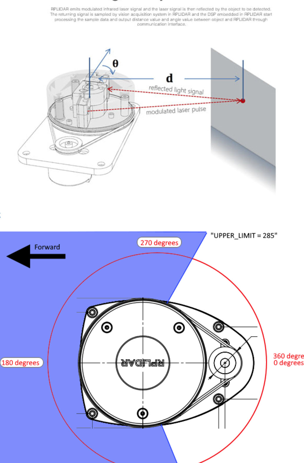
3. Manually Set dist_msg.min_distance, max_distance, increment, and distances
-
We manually defined min/max range in cm (e.g. 10 to 1000).
-
Converted and clamped the LIDAR readings appropriately.
4. Respected MAVLink Limits
-
Only 72 distance values (angles) allowed per message.
-
increment in centi-degrees: calculated manually from LaserScan.angle_increment.
5. No Existing ROS 2 Plugin
-
In ROS 1: MAVROS had a distance_sensor plugin for this.
-
In ROS 2: I manually replicated that behavior with the custom Python node.
Result:
This approach gave ROS 2-compatible obstacle avoidance over MAVLink, functionally equivalent to how ROS 1 would work with OBSTACLE_DISTANCE.
RPLIDAR C1 + ROS 2 Humble + MAVROS + OBSTACLE_DISTANCE (May 2025)
System Overview
• Device: Raspberry Pi 4 (or Pi 5, both tested)
• OS: Ubuntu Server 22.04.3 LTS (64-bit)
• ROS: ROS 2 Humble Hawksbill
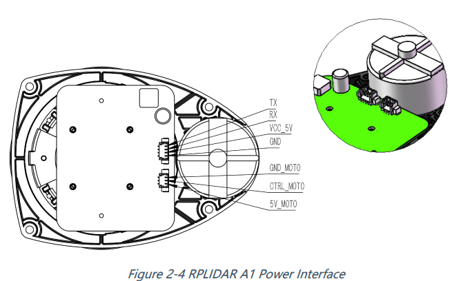
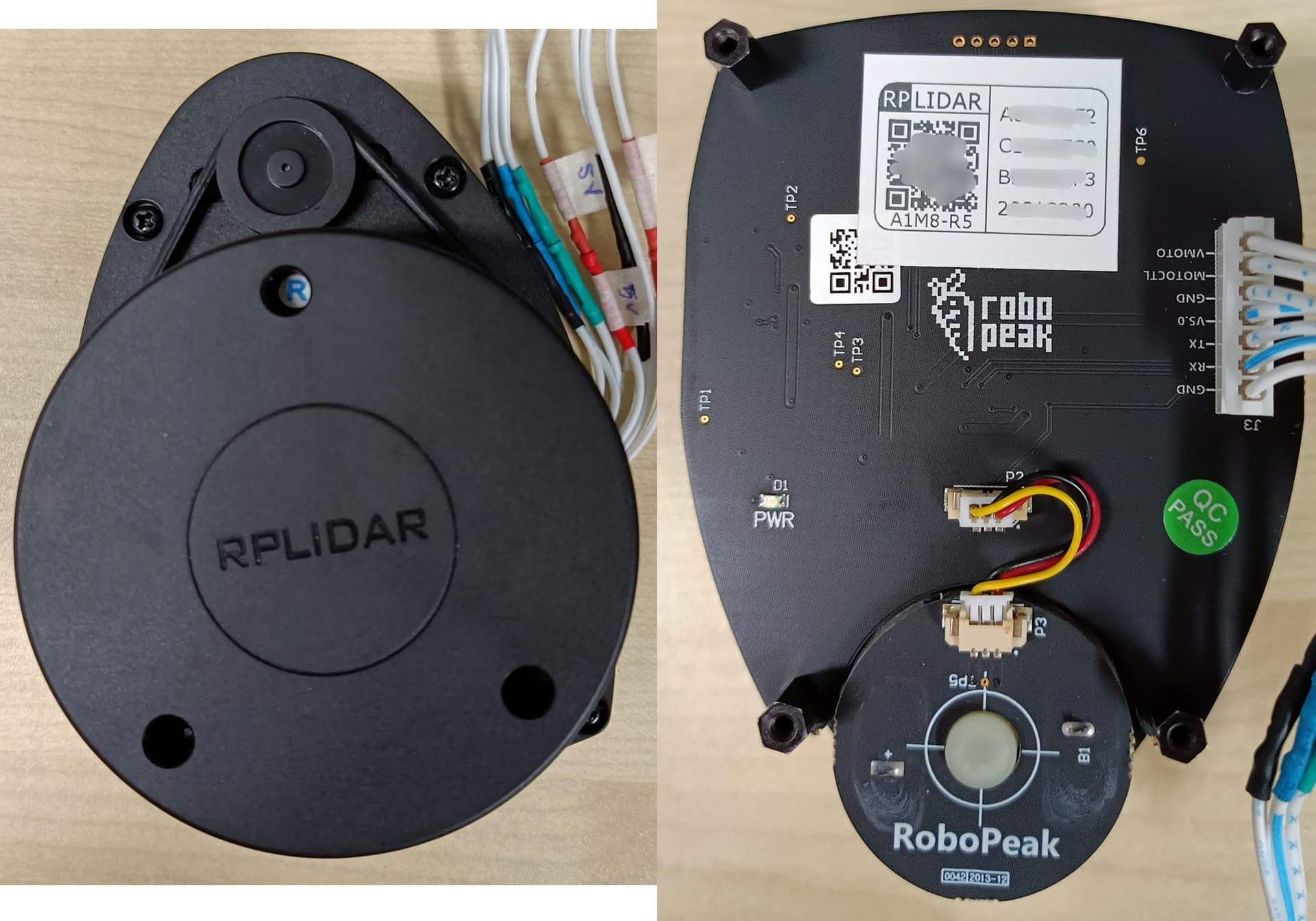
• LIDAR: Slamtec RPLIDAR C1
• Flight Controller: ArduPilot-compatible, connected via /dev/ttyAMA0
• LIDAR UART Port: /dev/ttyAMA1 at 460800 baud
• Auto-Start: systemd service drone_stack.service
OS & ROS 2 Setup
# Update & install dependencies
sudo apt update && sudo apt upgrade -y
sudo apt install -y curl gnupg lsb-release

# ROS 2 Humble install
sudo apt install software-properties-common
sudo add-apt-repository universe
sudo curl -sSL https://raw.githubusercontent.com/ros/rosdistro/master/ros.key | sudo tee /usr/share/keyrings/ros-archive-keyring.gpg > /dev/null
echo "deb [arch=arm64 signed-by=/usr/share/keyrings/ros-archive-keyring.gpg] http://packages.ros.org/ros2/ubuntu $(lsb_release -cs) main" | sudo tee /etc/apt/sources.list.d/ros2.list > /dev/null

sudo apt update
sudo apt install -y ros-humble-desktop python3-argcomplete

# Setup environment
echo "source /opt/ros/humble/setup.bash" >> ~/.bashrc
source ~/.bashrc
Workspace & Required Packages
# Create workspace
mkdir -p ~/rplidar_ws/src
cd ~/rplidar_ws

# Clone rplidar_ros (ROS 2 branch)
cd src
git clone -b ros2 https://github.com/Slamtec/rplidar_ros.git

# Create scan_to_mavlink Python package
ros2 pkg create --build-type ament_python scan_to_mavlink --dependencies rclpy sensor_msgs mavros_msgs std_msgs
![]() scan_to_mavlink_node.py (main logic)
scan_to_mavlink_node.py (main logic)
cat <<EOF > ~/rplidar_ws/src/scan_to_mavlink/scan_to_mavlink/scan_to_mavlink_node.py
#!/usr/bin/env python3

import rclpy
from rclpy.node import Node
from sensor_msgs.msg import LaserScan
from mavros_msgs.msg import ObstacleDistance
import numpy as np

class ScanToMavlinkNode(Node):
    def __init__(self):
        super().__init__('scan_to_mavlink_node')
        self.subscription = self.create_subscription(LaserScan, '/scan', self.scan_callback, 10)
        self.publisher = self.create_publisher(ObstacleDistance, '/mavros/obstacle/send', 10)

    def scan_callback(self, msg):
        dist_msg = ObstacleDistance()
        dist_msg.header = msg.header
        dist_msg.sensor_type = ObstacleDistance.MAV_DISTANCE_SENSOR_LASER
        dist_msg.min_distance = int(msg.range_min * 100)
        dist_msg.max_distance = int(msg.range_max * 100)
        deg100 = int((msg.angle_increment * 180.0 / 3.14159) * 100)
        dist_msg.increment = min(deg100, 255)
        ranges = np.clip(np.array(msg.ranges), msg.range_min, msg.range_max)
        distances_cm = (ranges * 100).astype(np.uint16)
        if len(distances_cm) > 72:
            distances_cm = distances_cm[::len(distances_cm)//72][:72]
        dist_msg.distances = distances_cm.tolist()
        dist_msg.angle_offset = 0
        dist_msg.frame = 0
        self.publisher.publish(dist_msg)

def main(args=None):
    rclpy.init(args=args)
    node = ScanToMavlinkNode()
    rclpy.spin(node)
    node.destroy_node()
    rclpy.shutdown()

if __name__ == '__main__':
    main()
EOF
chmod +x ~/rplidar_ws/src/scan_to_mavlink/scan_to_mavlink/scan_to_mavlink_node.py
![]() setup.py
setup.py
cat <<EOF > ~/rplidar_ws/src/scan_to_mavlink/setup.py
from setuptools import setup

package_name = 'scan_to_mavlink'

setup(
    name=package_name,
    version='0.0.0',
    packages=[package_name],
    data_files=[('share/ament_index/resource_index/packages', ['resource/' + package_name]),
                ('share/' + package_name, ['package.xml'])],
    install_requires=['setuptools'],
    zip_safe=True,
    maintainer='Hendrik',
    maintainer_email='Hendrik@todo.todo',
    description='Convert /scan to MAVROS OBSTACLE_DISTANCE',
    license='MIT',
    entry_points={'console_scripts': ['scan_to_mavlink_node = scan_to_mavlink.scan_to_mavlink_node:main']},
)
EOF
![]() package.xml should include:
package.xml should include:
<exec_depend>mavros_msgs</exec_depend>
Install MAVROS from Apt
sudo apt install -y ros-humble-mavros ros-humble-mavros-extras
Build Workspace
cd ~/rplidar_ws
colcon build --symlink-install
source install/setup.bash
systemd Auto-Start
![]() start_drone_stack.sh
start_drone_stack.sh
cat <<EOF | sudo tee /home/Hendrik/start_drone_stack.sh > /dev/null
#!/bin/bash
source /opt/ros/humble/setup.bash
source /home/Hendrik/rplidar_ws/install/setup.bash

ros2 run rplidar_ros rplidar_node \\
  --ros-args -p serial_port:=/dev/ttyAMA1 -p serial_baudrate:=460800 &

sleep 2

ros2 run scan_to_mavlink scan_to_mavlink_node &

exec ros2 run mavros mavros_node \\
  --ros-args \\
  -p fcu_url:=serial:///dev/ttyAMA0:115200 \\
  -p gcs_url:=udp://@ \\
  -r __ns:=/uas1
EOF
sudo chmod +x /home/Hendrik/start_drone_stack.sh
![]() drone_stack.service
drone_stack.service
cat <<EOF | sudo tee /etc/systemd/system/drone_stack.service > /dev/null
[Unit]
Description=Auto-start RPLIDAR and MAVROS on boot
After=network.target

[Service]
ExecStart=/home/Hendrik/start_drone_stack.sh
User=Hendrik
WorkingDirectory=/home/Hendrik
Restart=on-failure
RestartSec=3

[Install]
WantedBy=multi-user.target
EOF
bash
CopyEdit
sudo systemctl daemon-reload
sudo systemctl enable drone_stack.service
sudo systemctl start drone_stack.service
![]() Final Verifications
Final Verifications
# Confirm processes
ps aux | grep -E 'rplidar_node|scan_to_mavlink_node|mavros_node' | grep -v grep

# Confirm scan and obstacle output
ros2 topic echo /scan --once
ros2 topic echo /mavros/obstacle/send --once
![]() Software Versions (as of May 2025)
Software Versions (as of May 2025)
• ROS 2: Humble Hawksbill
• MAVROS: 2.9.0-1jammy.20250410
• RPLIDAR ROS: Slamtec rplidar_ros branch ros2
• ArduPilot firmware: ArduCopter 4.5.7 (via MAVROS logs)