Getting started here myself. Too bad Amazon sent two sets of 12x10 tubes instead of a set of 12 x 10 and a set of 10 x 8.
I have a Raspberry Pi and Navio 2 I’m thinking of putting in this.
Getting started here myself. Too bad Amazon sent two sets of 12x10 tubes instead of a set of 12 x 10 and a set of 10 x 8.
I have a Raspberry Pi and Navio 2 I’m thinking of putting in this.
looking at several pictures here your approach makes most sense - an H frame. you need to use 4 10mm tubes for the frame and 2 long 16mm or 24mm tubes for motors - depending upon size. that is how pretty much most heavy lifters are built.
those 3d printed parts look like they can be a bit too heavy for models smaller than 450mm to make practical sense. just ditch 4 independent motor arms - it really has to be 2 long motor tubes at 90 deg angle to 4 frame tubes to sustain practical damage from possible crashes ok. foldability - it that was the intent, in my opinion, is a minus for such models, it only reduces rigidity and more prone to breaks.
devFrame is not a heavy lifter. @fnoop was sharing a pic from when we started this project a couple years ago; it was a tank when we started. Latest design is 2kg max. Not designed to fold. You can run two long arm tubes if you want. Our empirical crash test data says its not required. devframe has some unique design goals which are explained in docs.
ArduPilot setup page v1 is up on Docs
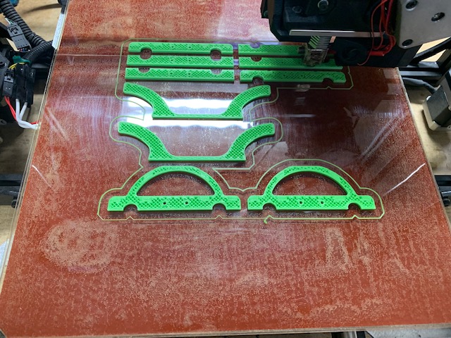
So my PLA printed frame is showing some signs of stress. I did have a failsafe which landed it in some trees and had a few hard landings when messing with RTL options.
First notice some cracks in my motor mounts

And while replacing one of those I noticed the arm was a bit loose 

Got a roll of PETG and will print replacements tomorrow and see how that holds up.
Once things open back up I may build an enclosure and eventually can do ABS but in the meantime I’ll improvise.
Good testing and feedback @thecrumb! Did you possibly tighten them too much? What infill were they printed with?
Also (unrelated) I’ve put out a call for help for suggestions to convert the devFrame to a rover, if anyone has any suggestions:
https://discuss.ardupilot.org/t/can-i-use-standard-escs-for-rover
Yep - 100% infill. I imagine they were stressed during a mishap and then when I tightened it a bit more it cracked.
Maybe @cglusky can advise better, but perhaps a smaller infill will actually allow more ‘give’ for the screws when they go in, and give less chance of cracking the body of material? I’ve often thought that screwing into a solid material places undue stress down natural stress lines.
I’ve been looking into getting a 3d printer in the last couple of weeks (versus ordering 3d prints off the internet), and the main thing that puts me off is the supposed difficulty of printing ABS. Getting a good recipe for printing PLA if it’s viable in the long term would be great as it would further lower the barrier to entry for the devFrame.
One confession - when I was screwing this together I just grabbed whatever screw I could find so some of them may have been a bit too big. I’ve since acquired the correct screws.
I may try to print these replacements with less infill - just because I’m impatient. I’m also hoping the PETG is a bit stronger than PLA but without the hassles of ABS. This is my first 3d printer (a Sovol SV01) and I’m having a blast. I know a lot of people spend hours calibrating and modifying things but so far everything I’ve printed has been functional and while maybe not ‘perfect’ it’s good enough.
Thanks for pioneering the way :). I know nothing about 3d printing other than what I’ve picked up from @cglusky through my devFrame experiments, ordering stuff online. Just to note all the stuff I’ve ordered online has been ABS and 20% infill, and it’s incredibly strong. I actually find the low infill provides like a ‘crush’ structure that deforms instead of breaks on impact.
I think it has more to do with properties of PLA vs ABS then infill. PLA is just more brittle. But it’s also easier to print. So if you had a bunch of spares you could keep flying. Trouble occurs when failures happen in flight. So there is additional risk. I do not have experience with PETG but have a friend who has been running it on prototype ROVs with success.
I cheat my solid parts with 90% infill. 50% infill on other parts could be lower but would need much more testing. Just easier and safer to error towards more infill.
Looks like your arm tube clamps need to change print orientation. Z axis of print should follow arm tube. Helps reduce cracking when applying clamping force.
If you print the arm tube clamps with right z orientation and keep plenty of motor mount and landing gear spares PLA could work for short term prototypes? Even if that is true I am not sure it is something we can recommend in docs just due to potential failure of motor mount in flight.
I had some hard time assembling arms tube mounts and box ends together, my tapping screws do not tighten well. What do you think about changing the tapping screws to standard M3 screws? It would require some design modifications but allow to assemble and disassemble the frame as many times as you want (could be useful to dismount arms for rover as well).
@cglusky Perfect timing - was just going to re-print. Rotated this in Cura and will see how it goes!
I just used PLA because I was impatient and I had a lot of it available. And I have been banging on this thing pretty good so overall I’d re-use PLA - with the warning that you do frequent inspections pre-flight, post crash.
Trying PETG now and hopefully that will be a nice balance between ABS and PLA from what I’ve read.
We started with M3 and threaded inserts. Decided that being able to source fasteners locally and easily was more important than handling a large number of fastener cycles.
Could you explain in more details what kind of issues you are having with using #6 screws? I am using pointed pan heads with no issues at all. So I am wondering if a true self taping point creates issues. For soft material like wood and plastic pointed is usually preferred. But it’s weird as what we are using also falls under sheet metal fasteners.
I have built my 3,5 Kg hexa also with a 3D printer. I would prefer ABS rather than PLA. I have used 80% infill but with lower part sections. Good part design is necesary to reduce weight and increase rigidity. I have also tried Nylon-CF filament but, in my case and with my printer, I had better result with ABS. I also used rounded arms, but I won’t do it again. With ABS and CF arms, you need a lot of preassure or a tape to hold the arm and to avoid motor tilt. A squared tube will solve the problem. I remember that when I built my hexa (three years ago) CF squared arms were hard to find and even more expensive, but now they are easier to find.
Part of the reason we are restricted to 2kg is use of rather small round arm tubes without physically indexing the motor mounts. It works well enough for this use case. Square tubes would make things easier to build but they are still a bit harder to reliably source vs round. And square CF tubes (wrapped; not pultruded) are more expensive last I checked. I think you would have to pay someone to do a large production run of small square CF tubes to make it work at our price point. We could go with small aluminum square but also hard to find; especially in thin walled.
Just checking in to see how things go? Docs are stalled for a bit longer while I attend a class. Next up will be prepping for first flight and then tuning.
I finally have all my Stuff Will start assembling this weekend