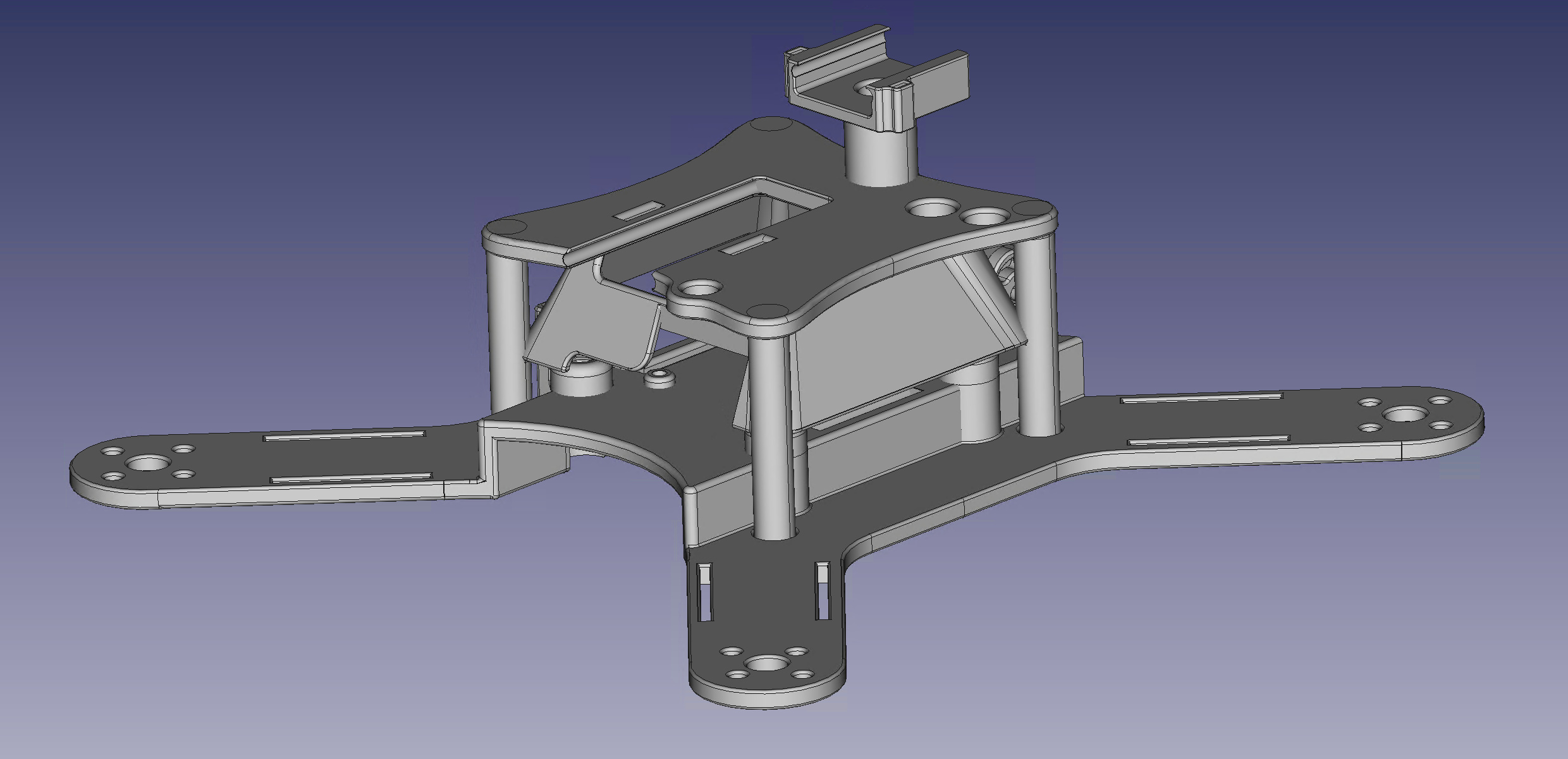
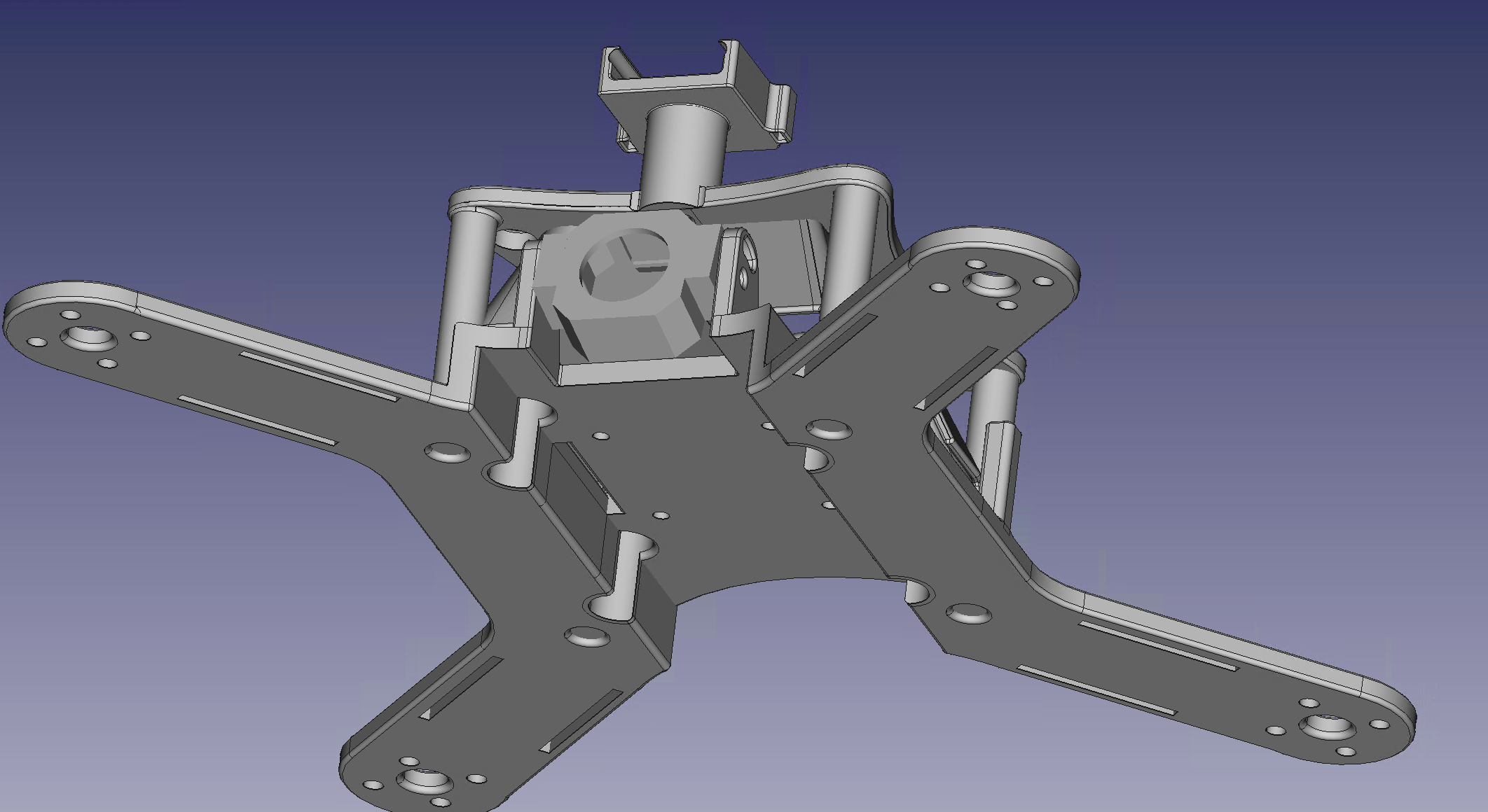
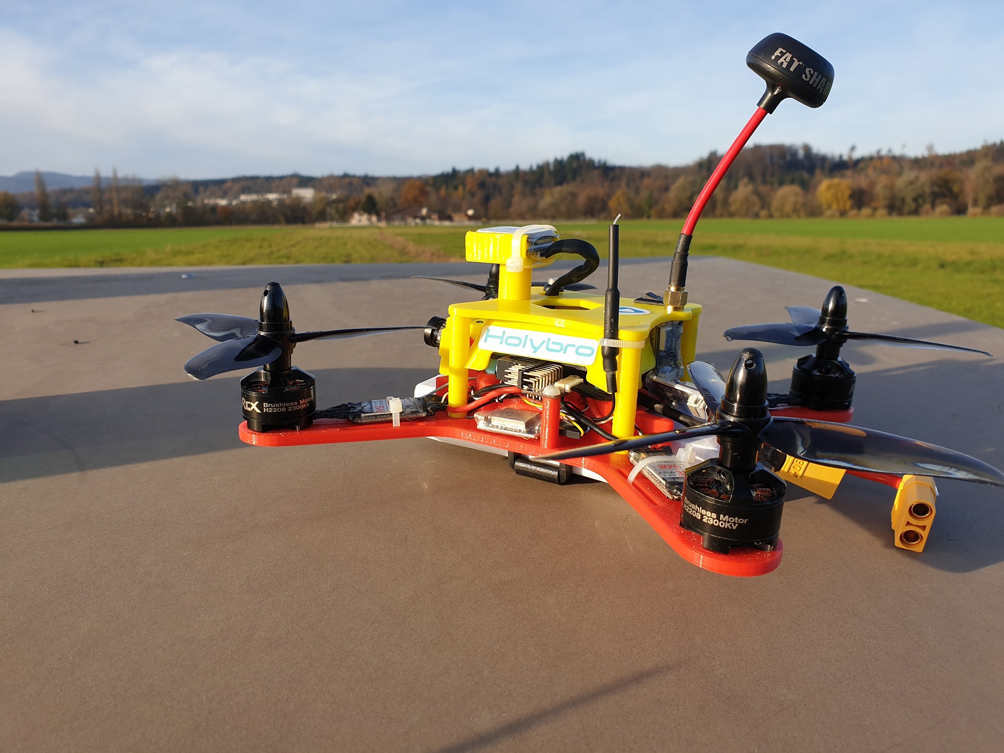
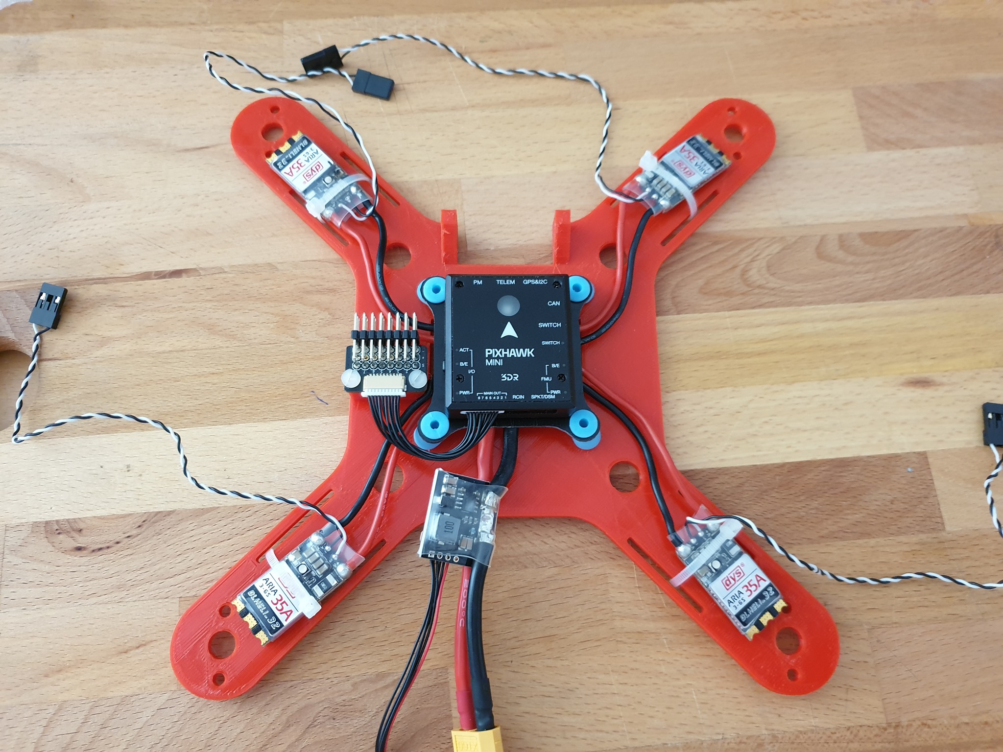
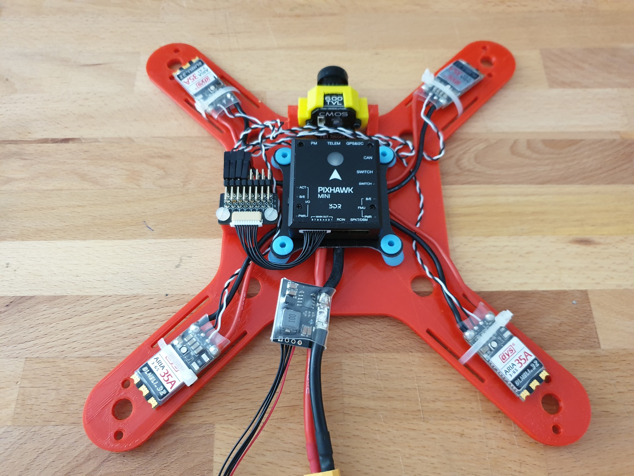
It’s been a while, but for a long time I had the idea to build an FPV Race Copter myself. The frame should be designed in CAD and 3D printed. The frame is made of one piece and has already integrated the damper mounts for the Pixhawk mini. The center of gravity is pretty accurate in the middle so that we can assume very good flight characteristics. The area of application should be fast FPV flights and Acrobatic. A mission should also be possible so as not to be unlearned.
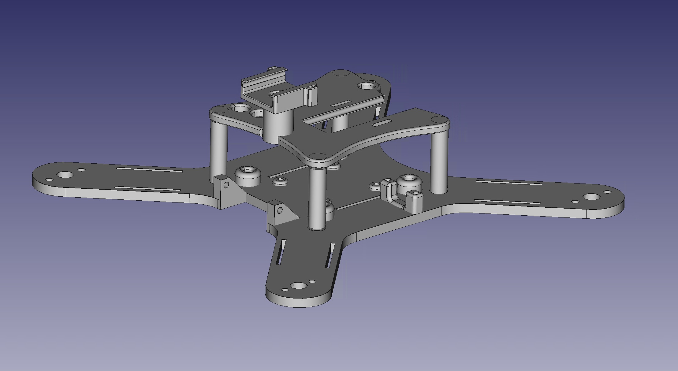
For the Design i used 3D Freecad an excellent CAD program (see top image)
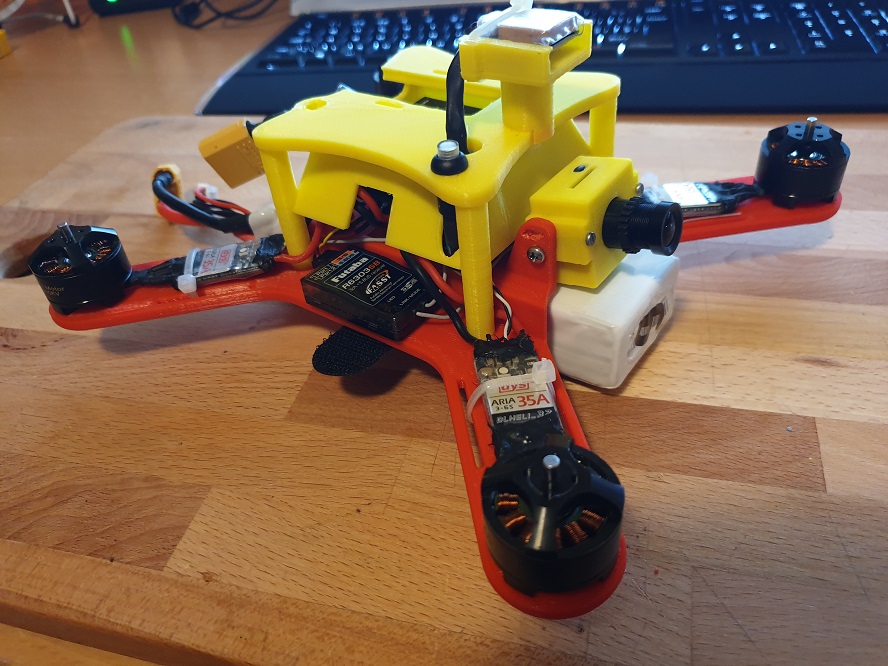
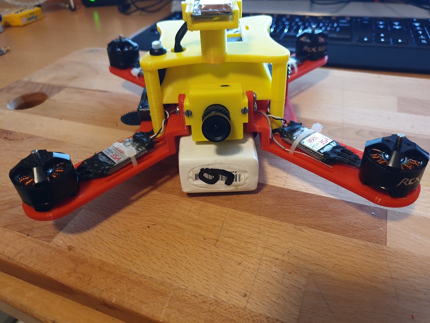
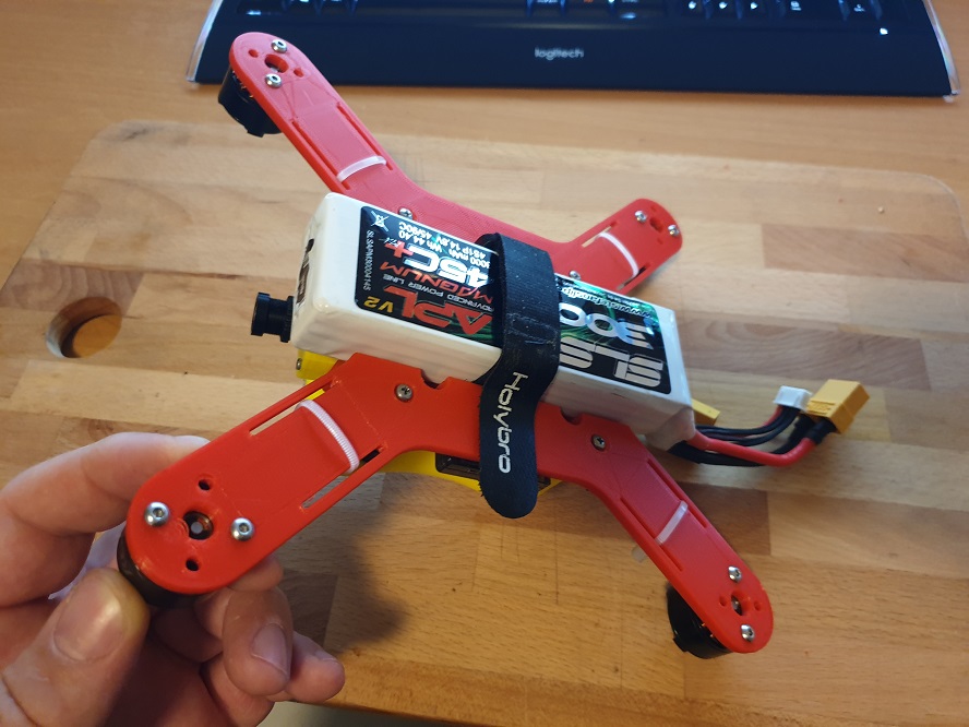
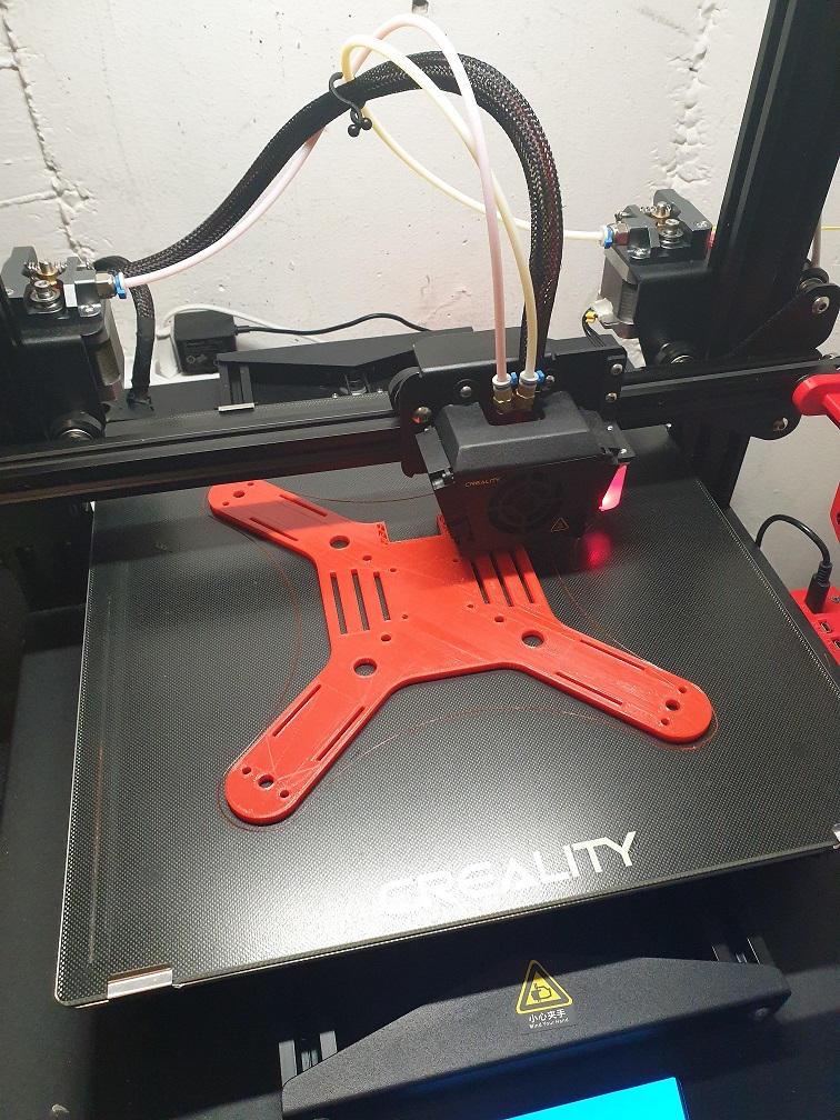
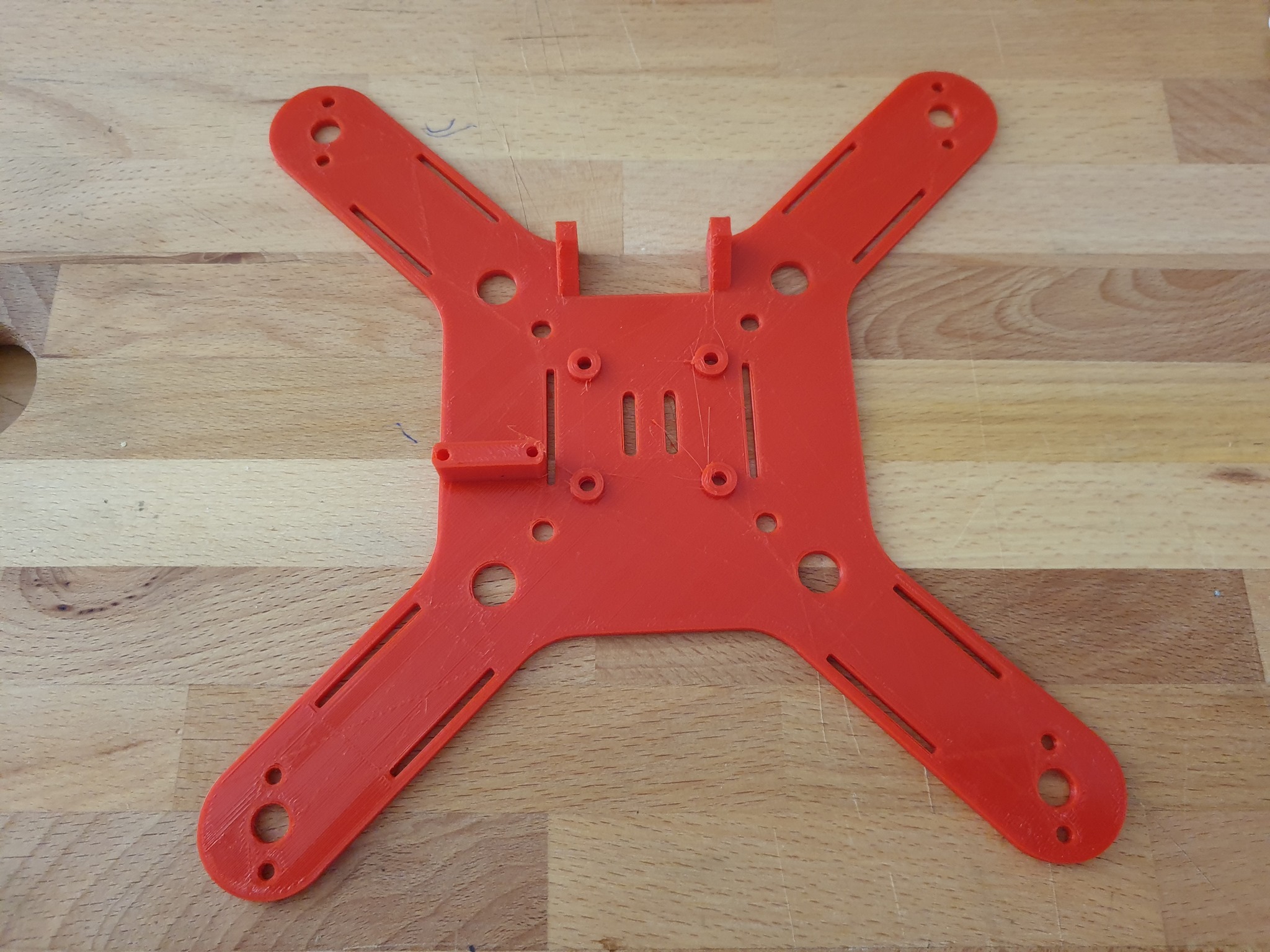
The Frame’s Print duration is about 7h, in the Picture one of the early stages, later on i did some improvement.
Nice project. I also love making new drones from scratch.
I have designed a medium size hexa with freecad and 3D printed.
If you may consider them, I would like to make some remarks:
The flat arms, printed with plastic (ABS or PLA) would result very flexible. You may end up having some problems to tune it. I have started a second project, also for 3D printed drones, based on topology optimization to achieve higher stiffness. After a long time, I am building the frame this week. You can find the blog here Building a quad frame on the basis of topology optimization
I don’t know which material you have used, but PLA is too brittle for drones, if possible, print with ABS or Nylon-CF. (I had better results with ABS than with Nylon-CF, but I think that it is because I didn’t find the perfect parameters to print with the last one).
Hi Andreasrc, sure i appreciate any input. Your project seems also nice to me.
For my prototype i used PLA but i plan to use ASA+ for the final version. The arms on my design are really short and together with the Top gives enough stiffness to the frame, i dont have any issues so far.
Consider that usually Internal 3D printed structures are very stiff and lightweight, is see a benefit to use PLA for its flexibility against brittle, what is speaking against PLA ist the poor Heat resistance of about 60°C.
What slicer do you use ?
I’ve already tuned the Copter with autotune with good values ATC over 250000.
Maybe i will post some logs later, IMU values also more than perfect. Its flying so well that im thinking about living it in PLA.
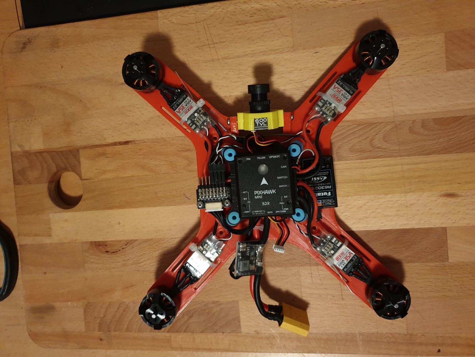
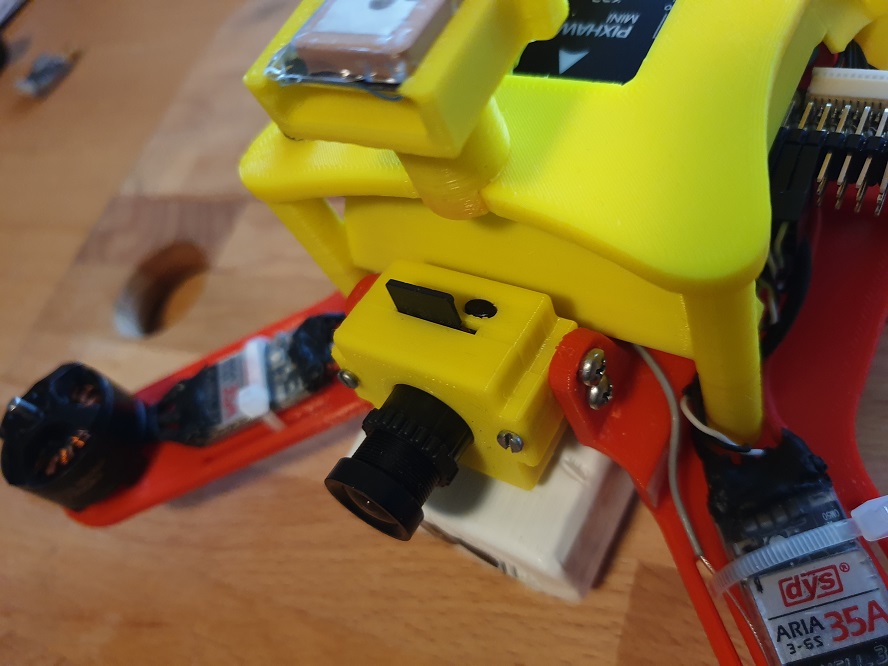
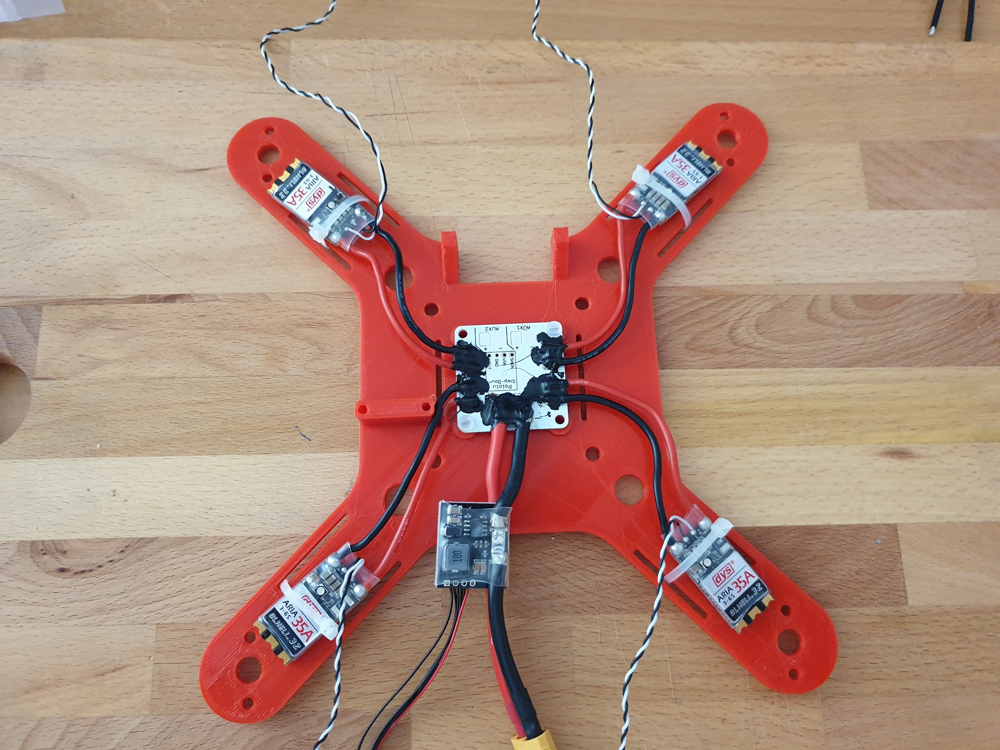
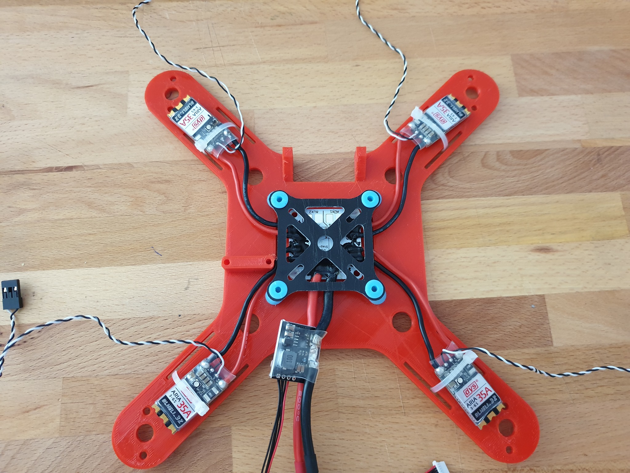
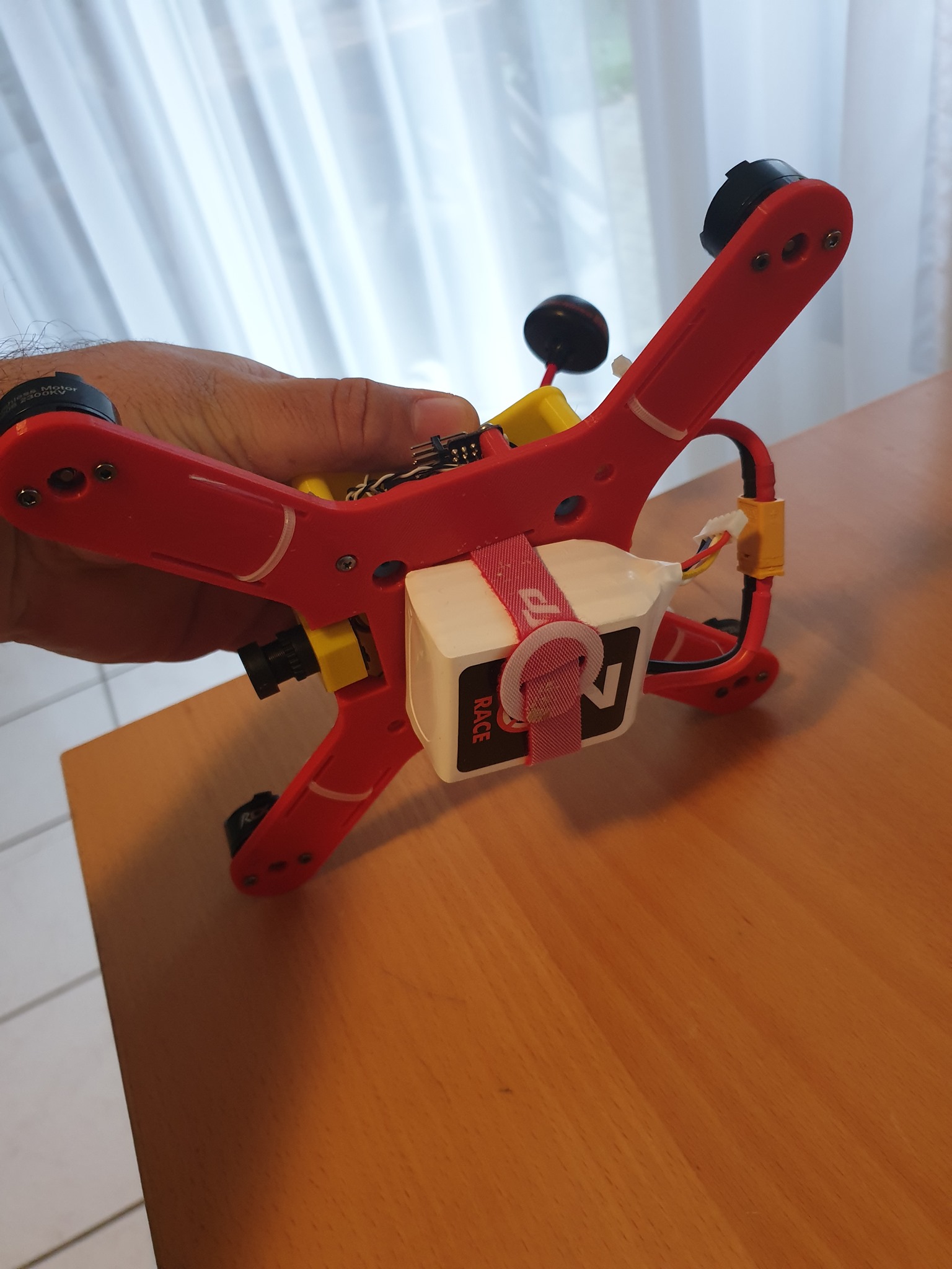
in my opinion the frame stiffness ist important but whats making a difference ist the Pixhawk / FC mount. Its very important to avoid any type of IMU errors due to vibrations. The best way to avoid vibration is to use Foam or any type of Shock/vibration absorber. How did you planed to mount the FC in your project ?
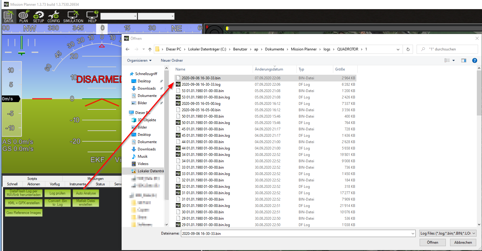
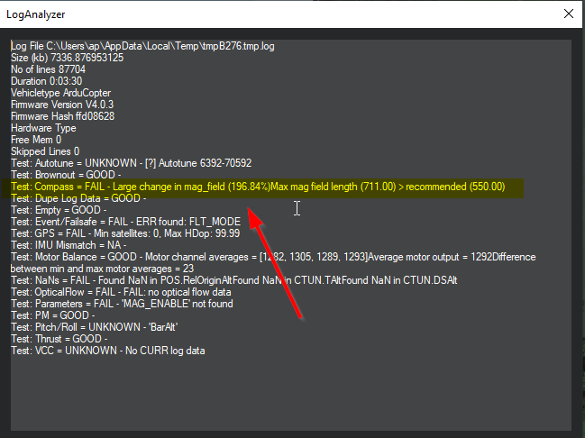
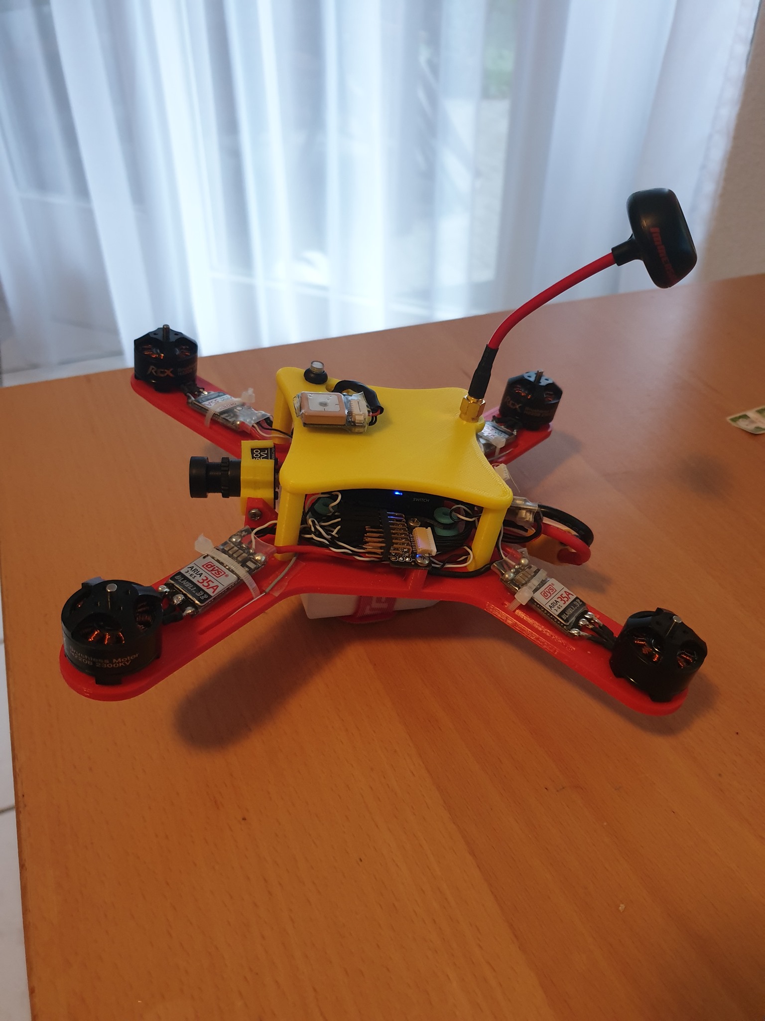
Let me give you a update on this one After some Test Flight i noticed quick that the GPS / Compass modul sitting on the Top is to near to the other Electronics and the Logs showed a big difference in MAG this is usually caused by interferences to the Compass. There is a quick way how to check, if you use Mission Planner record a flight and then Download the Log to your Computer then choose Auto Analyse
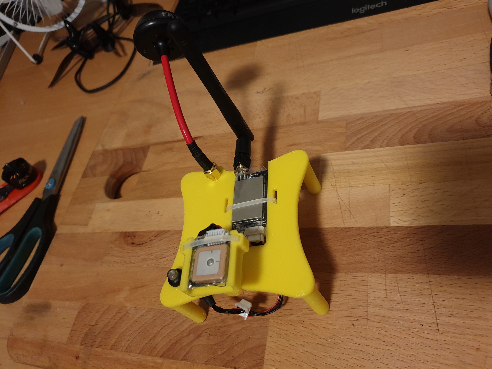
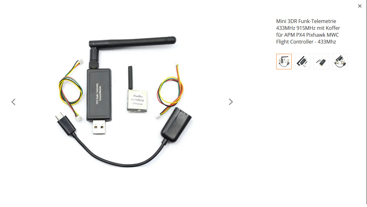
As i planned to update the Build anyway i did some changes related to the Top End. In the new version i integrated the Holybro Telemetry modul and lifted the GPS/Compass modul of about 20mm as some related tests showed much better behaivour.
Nice job on this project. I’d recommend changing the location of the Battery. If you “bounce” on landings or have a signal failure with failsafes and crash with a direct impact on the battery. Here’s a similar project I printed 3D parts for a quadcopter. ( https://youtu.be/oSnhcufzZxc )
Hi @btowner01 thanks and Welcome
There were on going modifications, i tested the copter in Acro and thought that the weight of the Battery should be more centered, to achive a better, more stable, Pitch/Roll rotation. Therefore the Battery is now integrated in the Frame so it secured and more centered.
Nice job. To get the fastest reaction the inertia moment should be minimum and centered with the propellers. The battery is exposed but handling should be good. I also would protect the battery with foam or plastic.
there is also FPV update, the new Camera from Fatshark Pilot HD has the advance of having on board recording to sdcard. i printed a new housing also for this camera as the original which it comes with is from steel and incredible heavy.
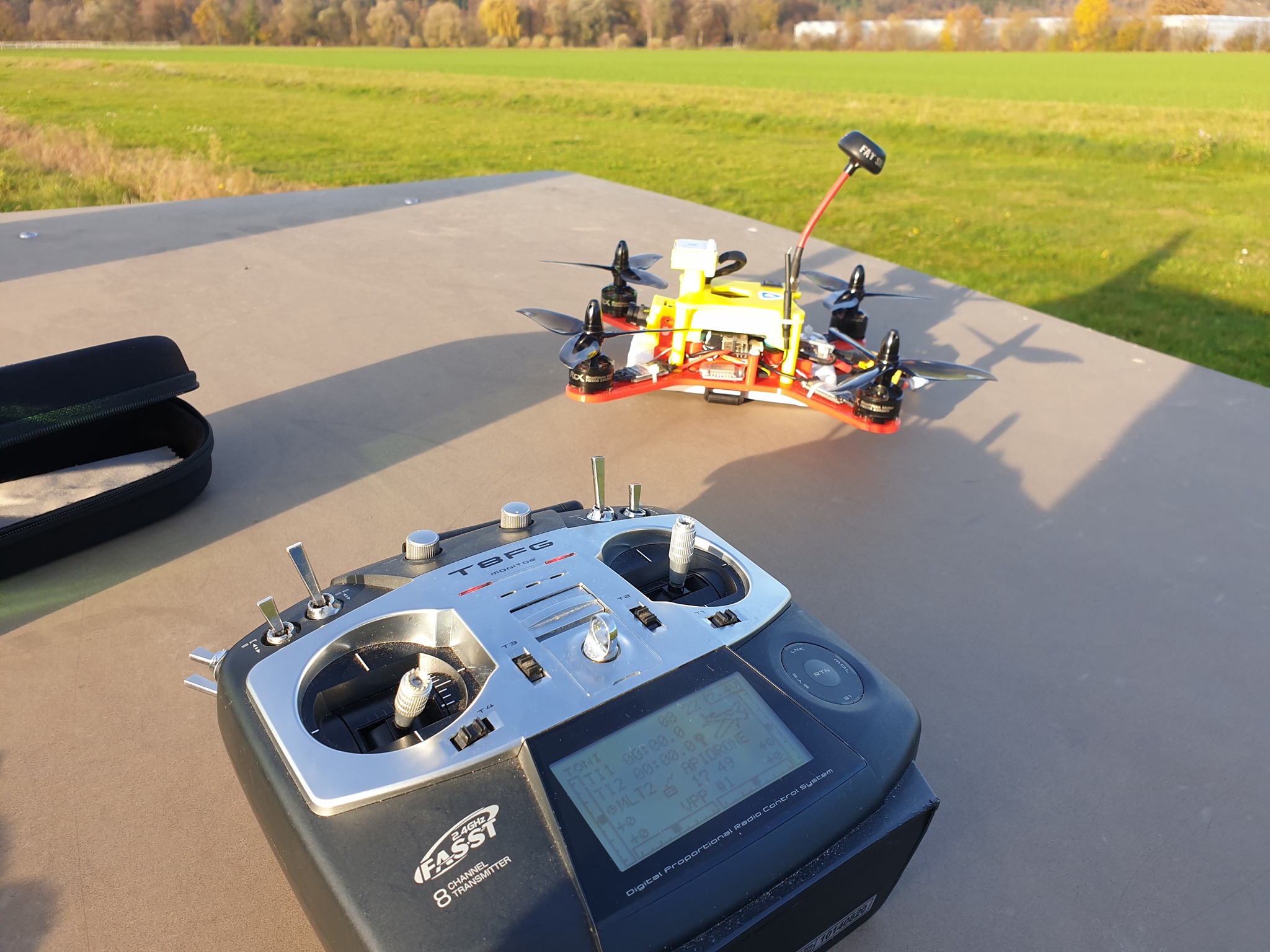
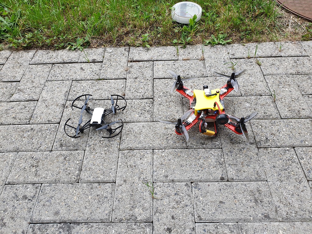
My Ardu-li 2, so I named the Fpv Racer, today it was the first time airborn. The weather was inviting on the airfield of the MFGE no people only an older couple on the bench at the edge of the forest watched eagerly. I tested all modes Althold, Loiter, Acro, Stabilize and so far everything has worked perfectly. I have to say that i replaced the micro GPS with a normale sized and the GPS Lock now takes only a few seconds, that much better now then before. The extra weight is compensate by the small WLAN module for Groundata instead of the big 433mhz module. I still have to test the range of this WLAN Module but today 80m was no problem, the manufacturer says that it is possible to go 300m.
.
Some key data from the data Log:
Maximum altitude flown today on sight 50m
Vertical acceleration 21m/s roughly comparable to 80 Km/h
Maximum speed in overflight 12m/s in about 50Km/h
My record with the big Heaxacopter is at an acceleration of 23m/s and a top speed of 35m/s about 120km/h.

 After some Test Flight i noticed quick that the GPS / Compass modul sitting on the Top is to near to the other Electronics and the Logs showed a big difference in MAG this is usually caused by interferences to the Compass. There is a quick way how to check, if you use Mission Planner record a flight and then Download the Log to your Computer then choose Auto Analyse