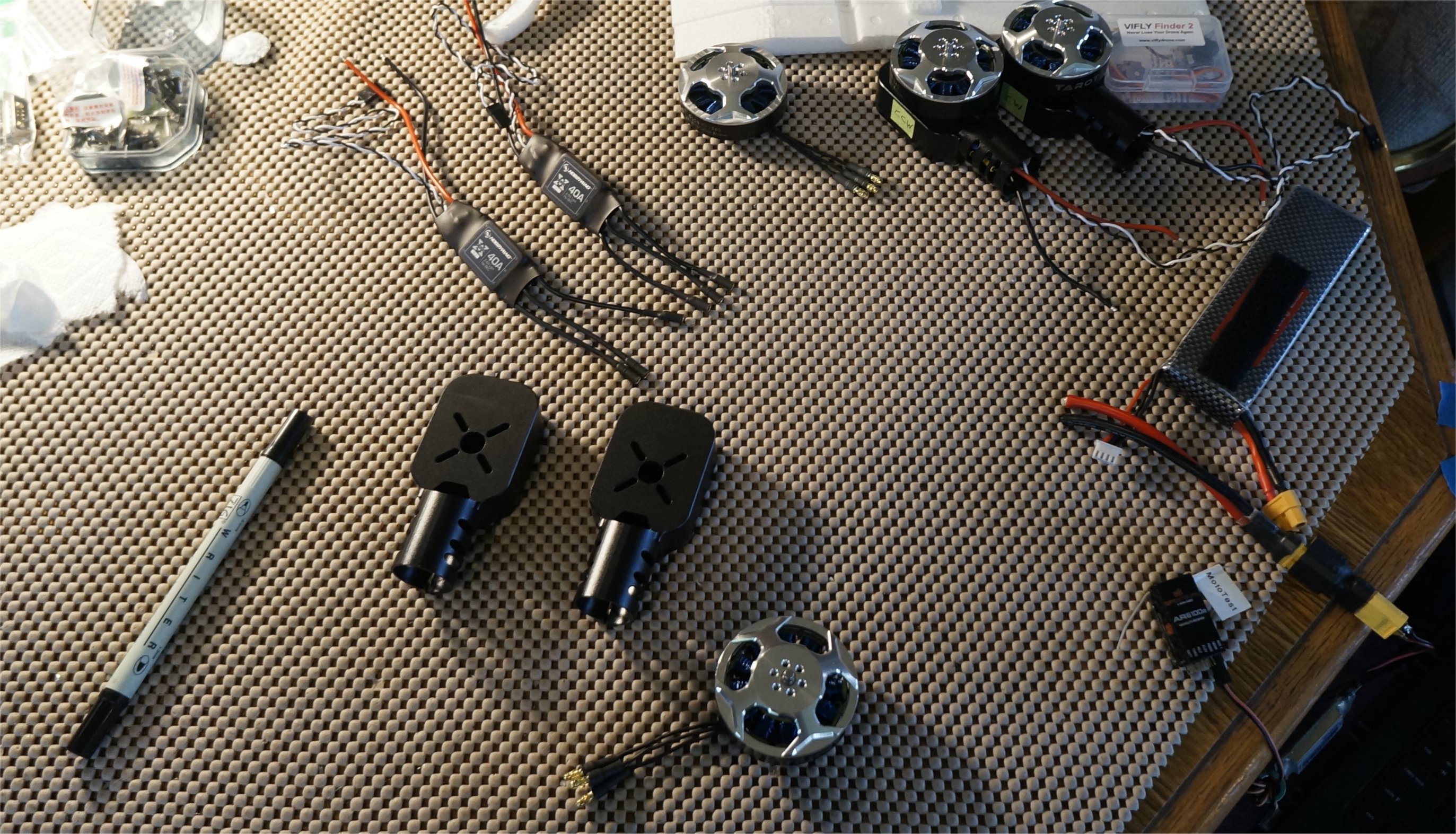
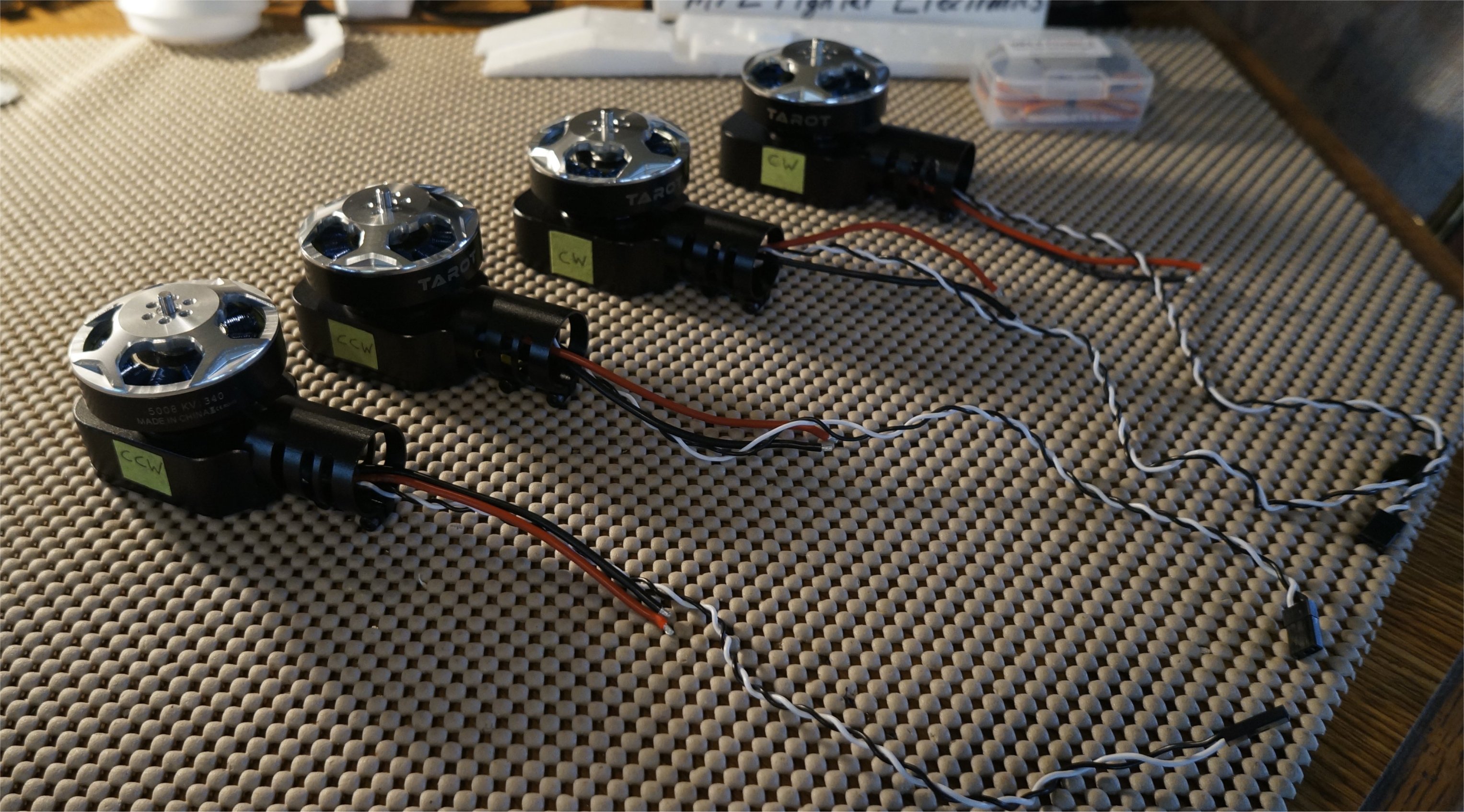
I assembled my four motor pods. The only soldering here was to add 3mm bullet connectors to the motor wires. Before closing the case, I tested the direction of rotation, using a spare receiver, and swapped two wires, if needed. Two pods turn CW and two turn CCW.
1 Like
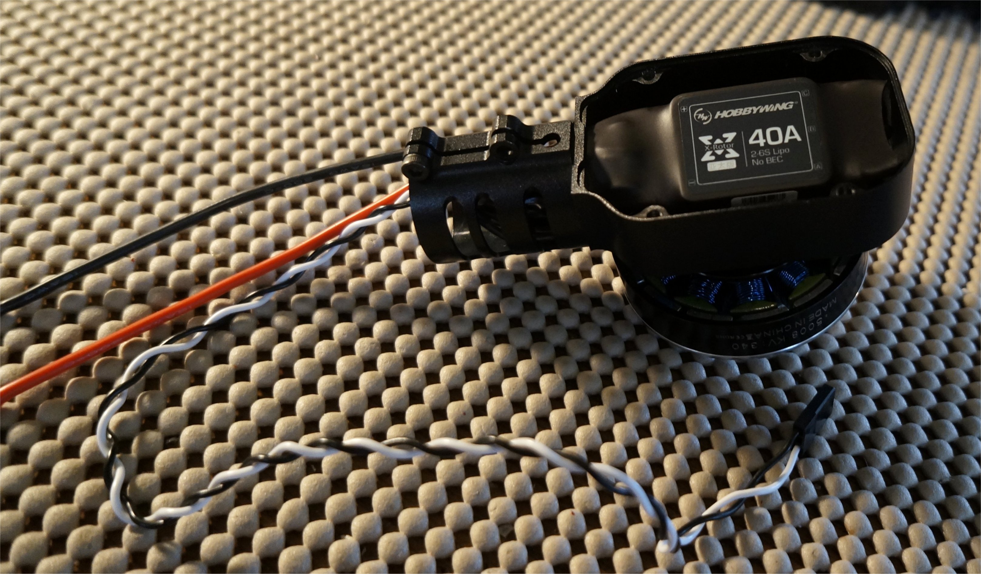
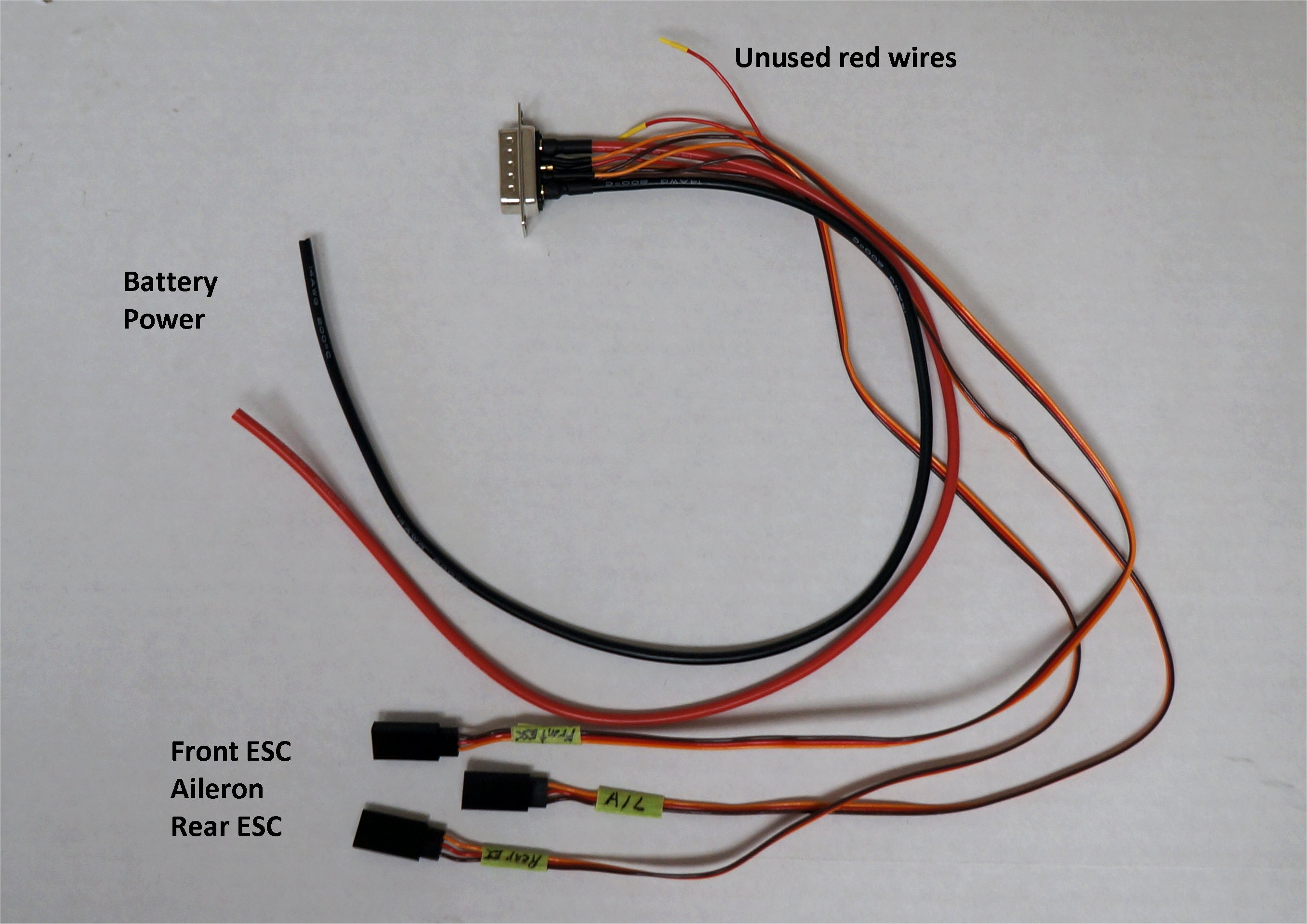
I soldered up my main wing connectors to mate with the fuselage connector and the wing servo connectors. When using the Hobbywing XRotor 40A ESCs (no BEC), the middle red wire is not used.
----------------------------- New Post --------------------------------
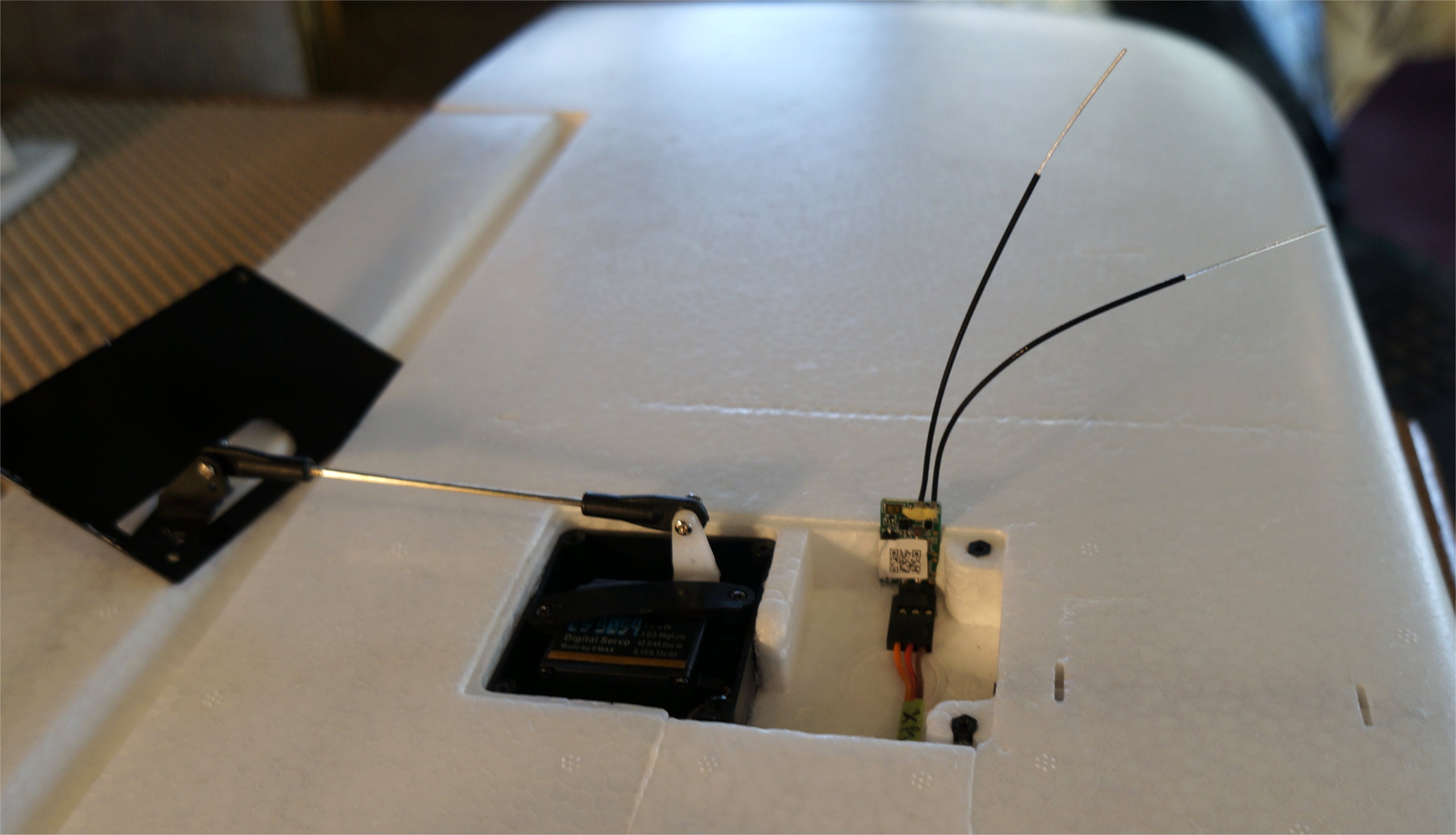
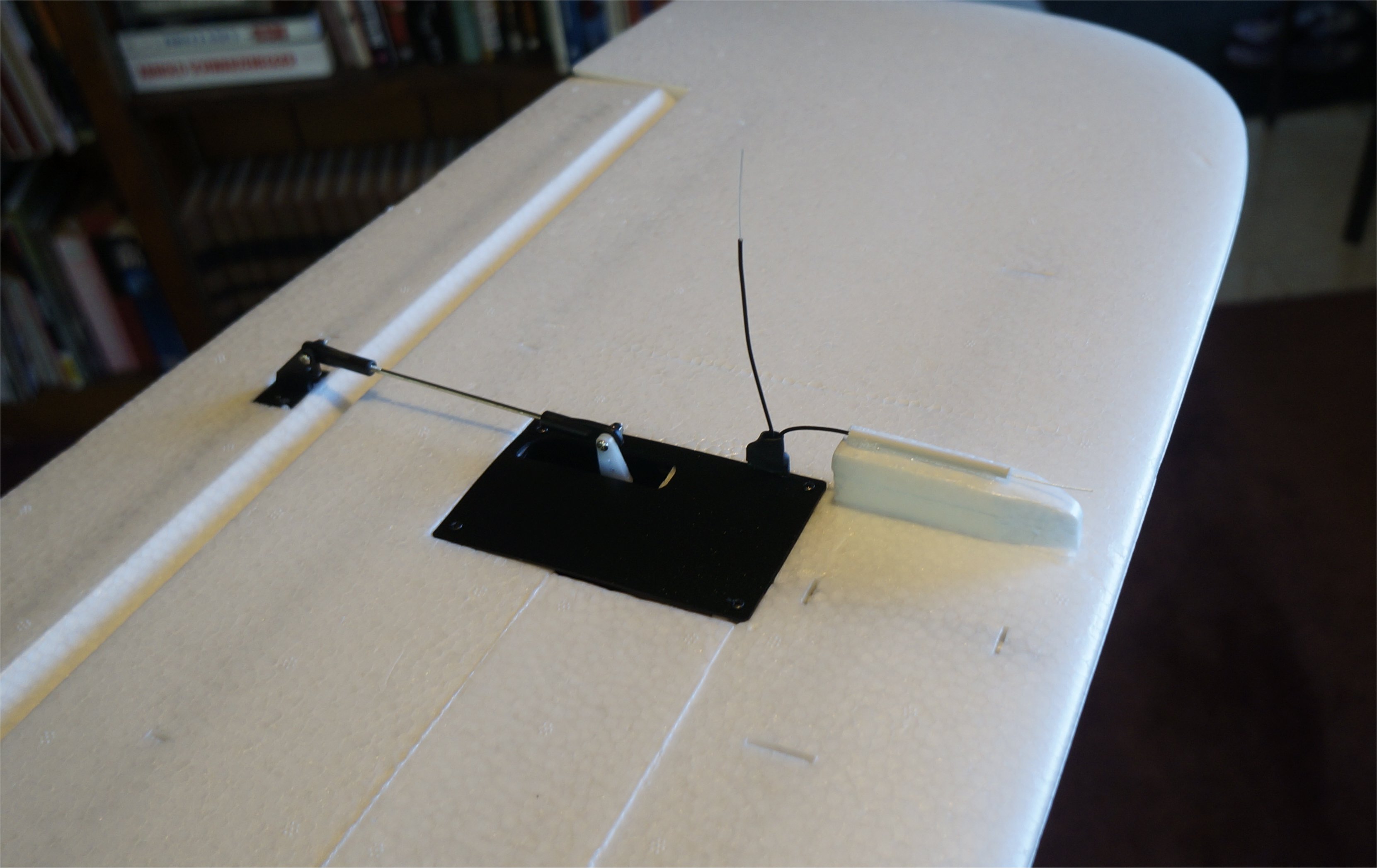
Since my AS sensor was installed on one wing, I decided to install my redundant XM+ receiver on the other wing. This put the two receivers about 3’ apart with different antenna orientations. I built up a foam channel for the antenna wire to stay about 90 degrees from the other wire.
----------------------------- New Post --------------------------------
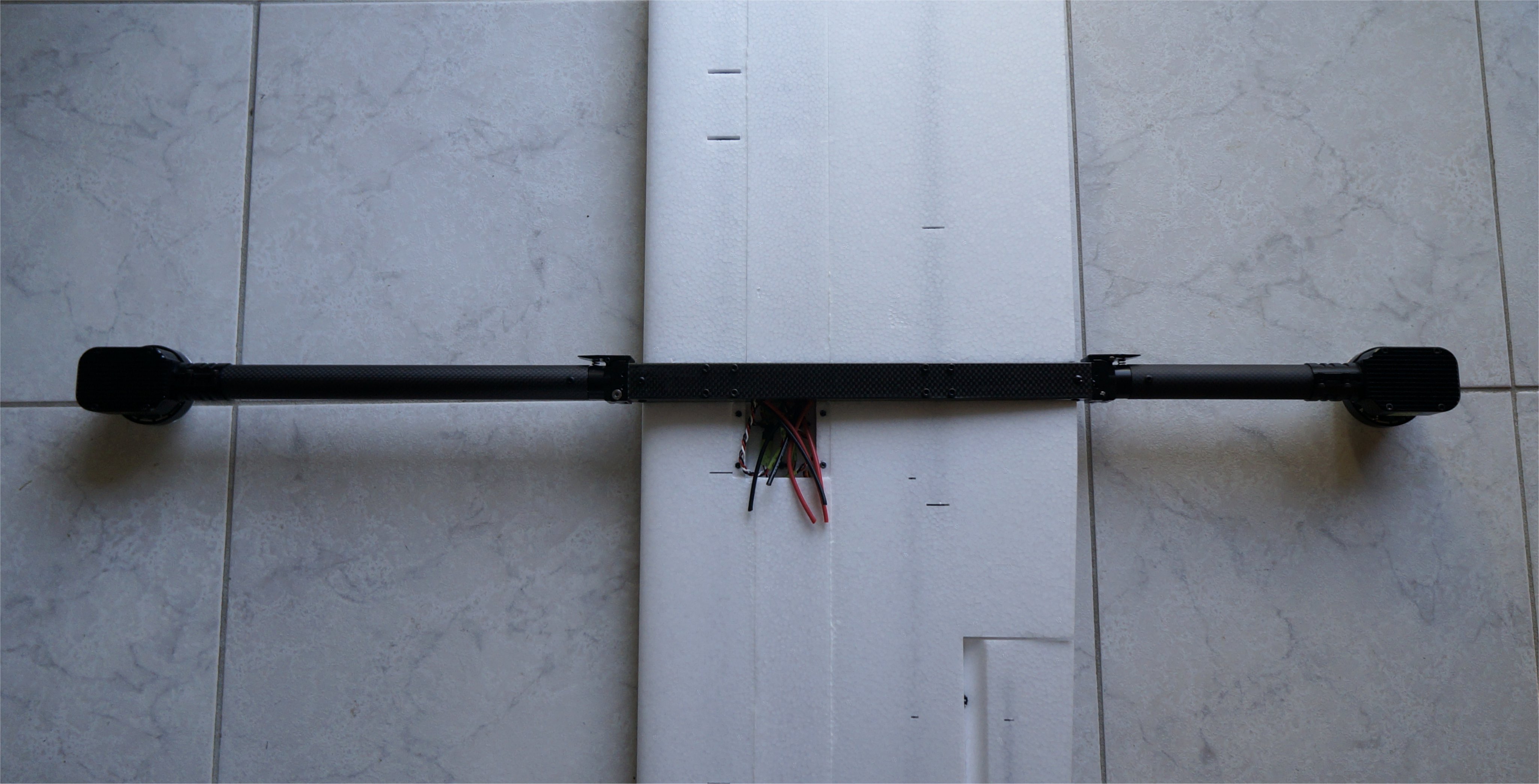
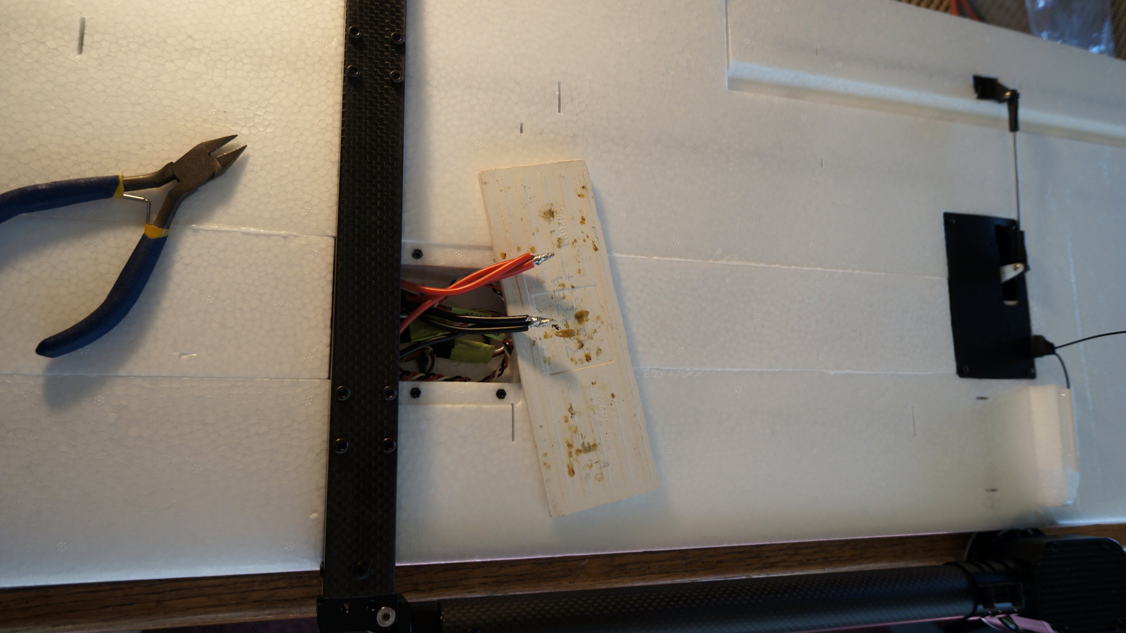
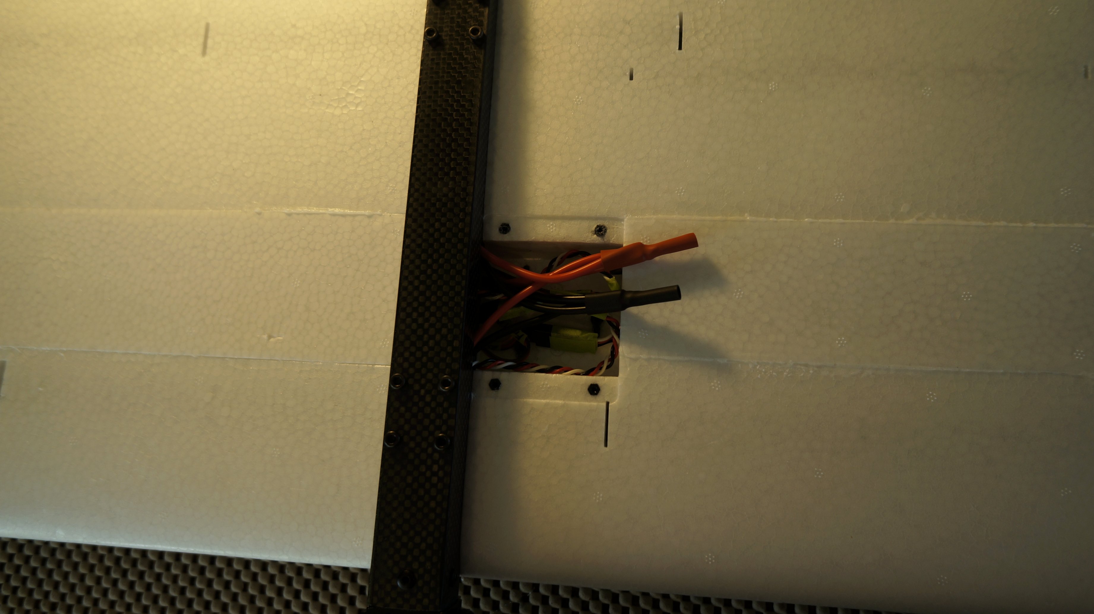
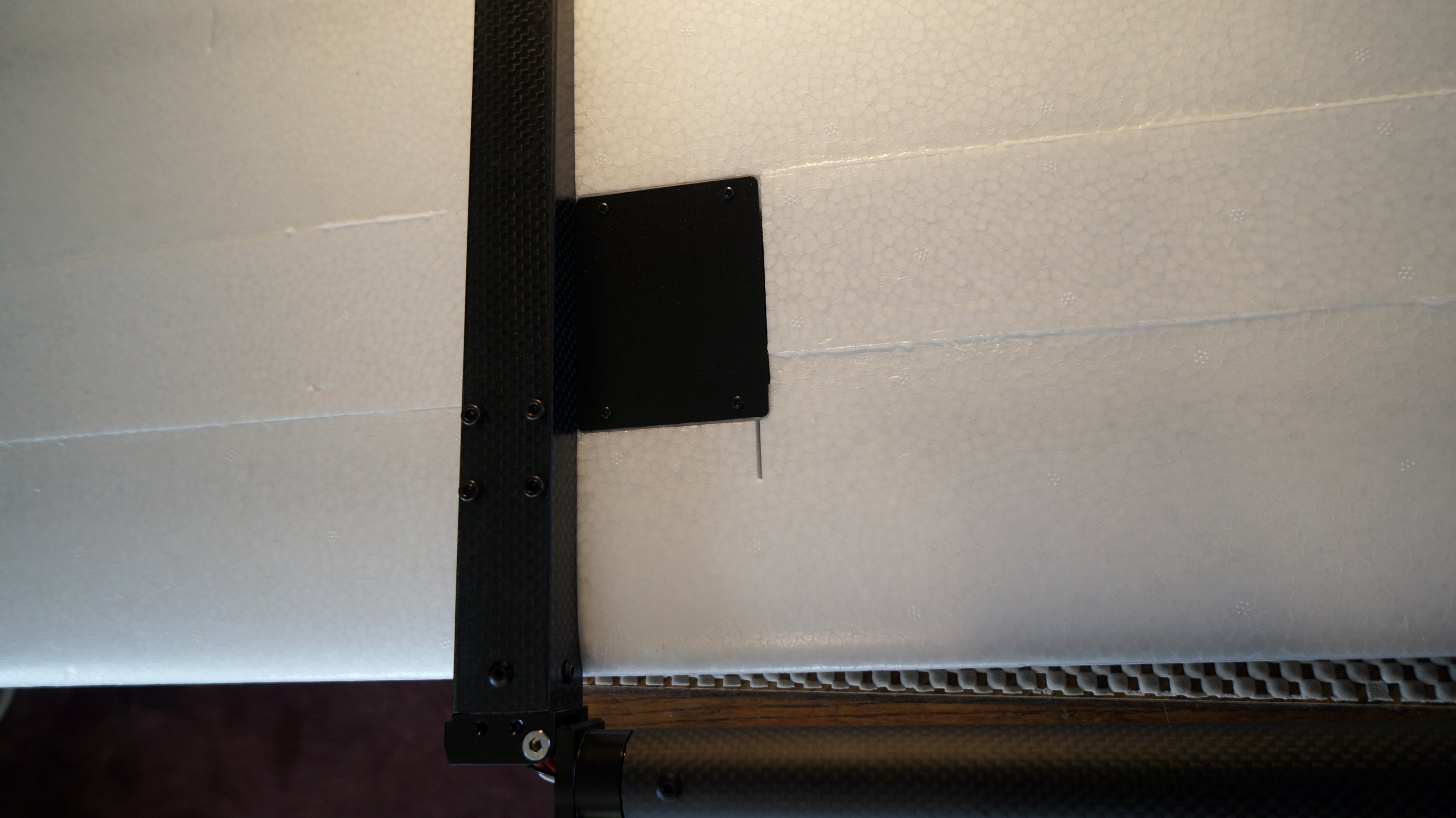
The correct rotation motor pods were installed on the quad tubes after first determining which tube was for the left wing and right wing. The servo connectors simply fit together. I soldered the three red wires and three black wires before covering the ends with shrink wrap. Once the cover plate was installed, the wing was complete. The same process was used for the left wing.
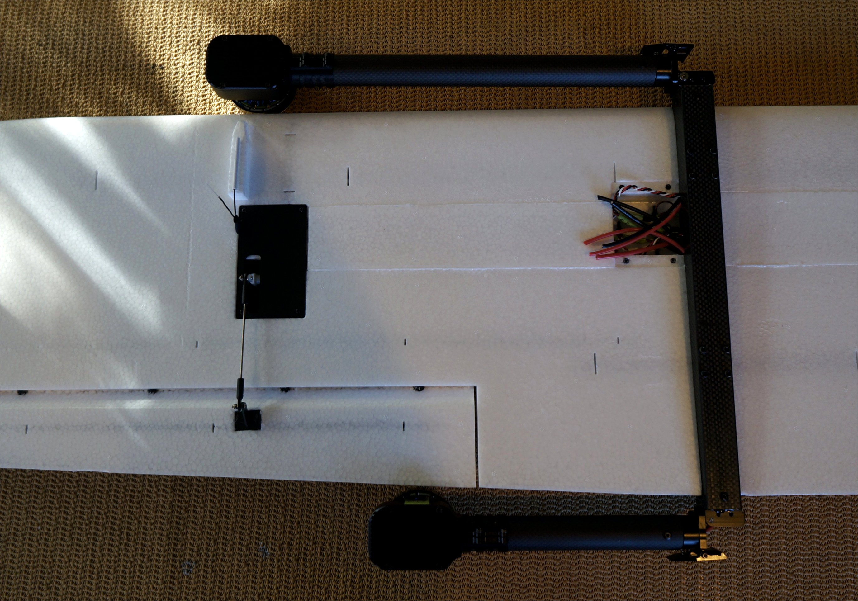
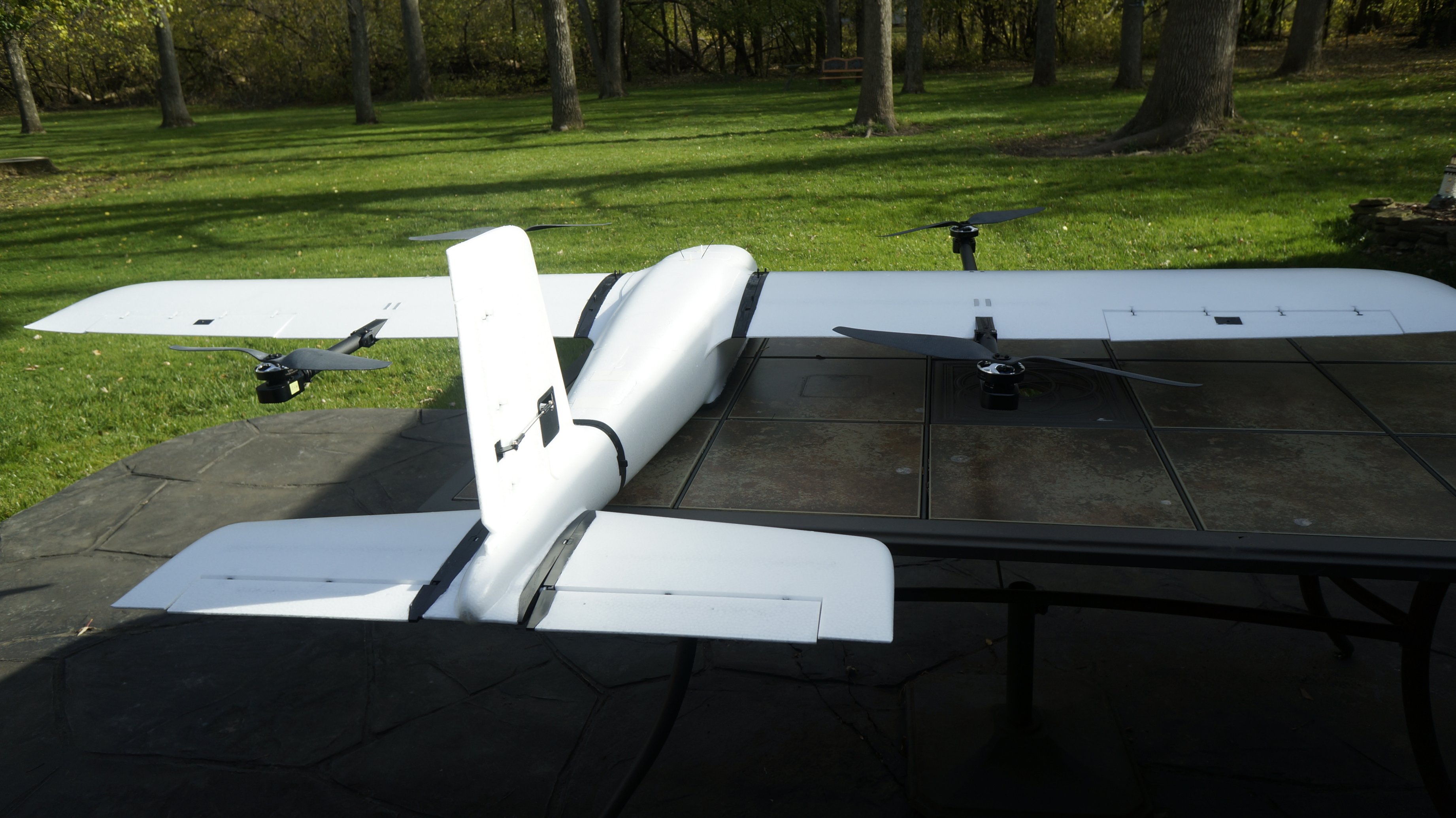
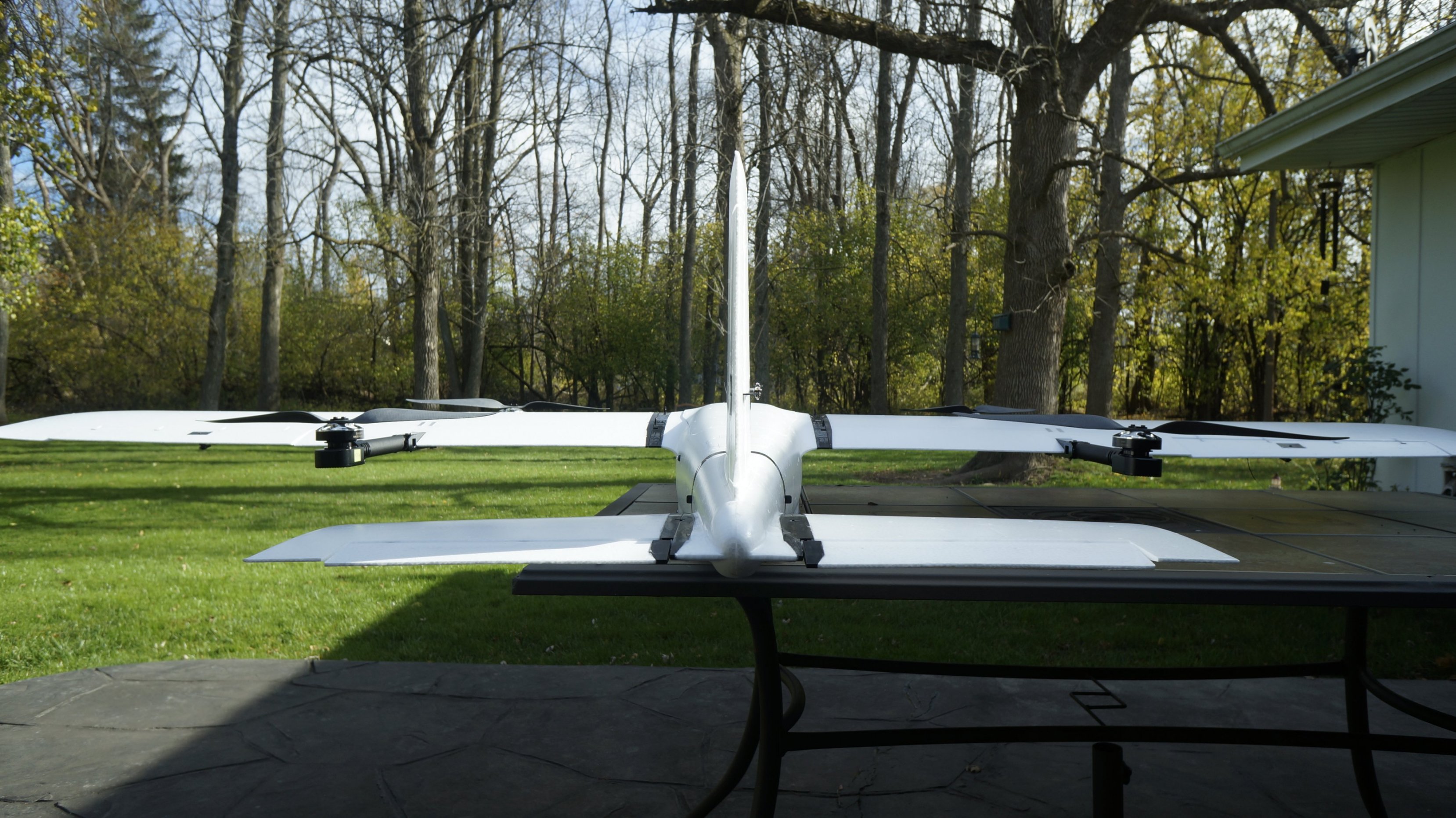
At this point, I have completed the initial assembly. I was impressed with how well everything fit. Other than all the required soldering, the kit was a joy to assemble!
----------------------------- New Post --------------------------------
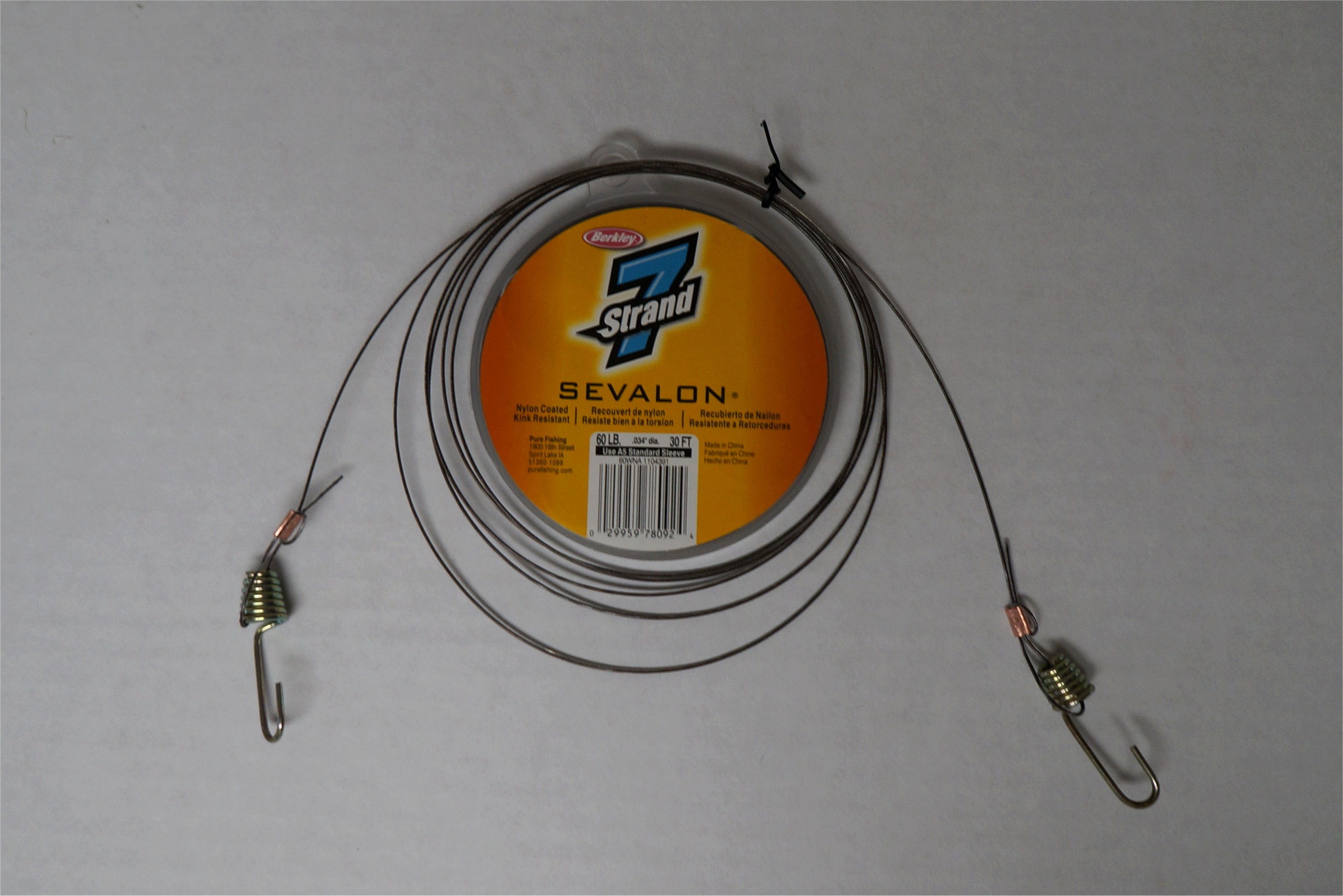
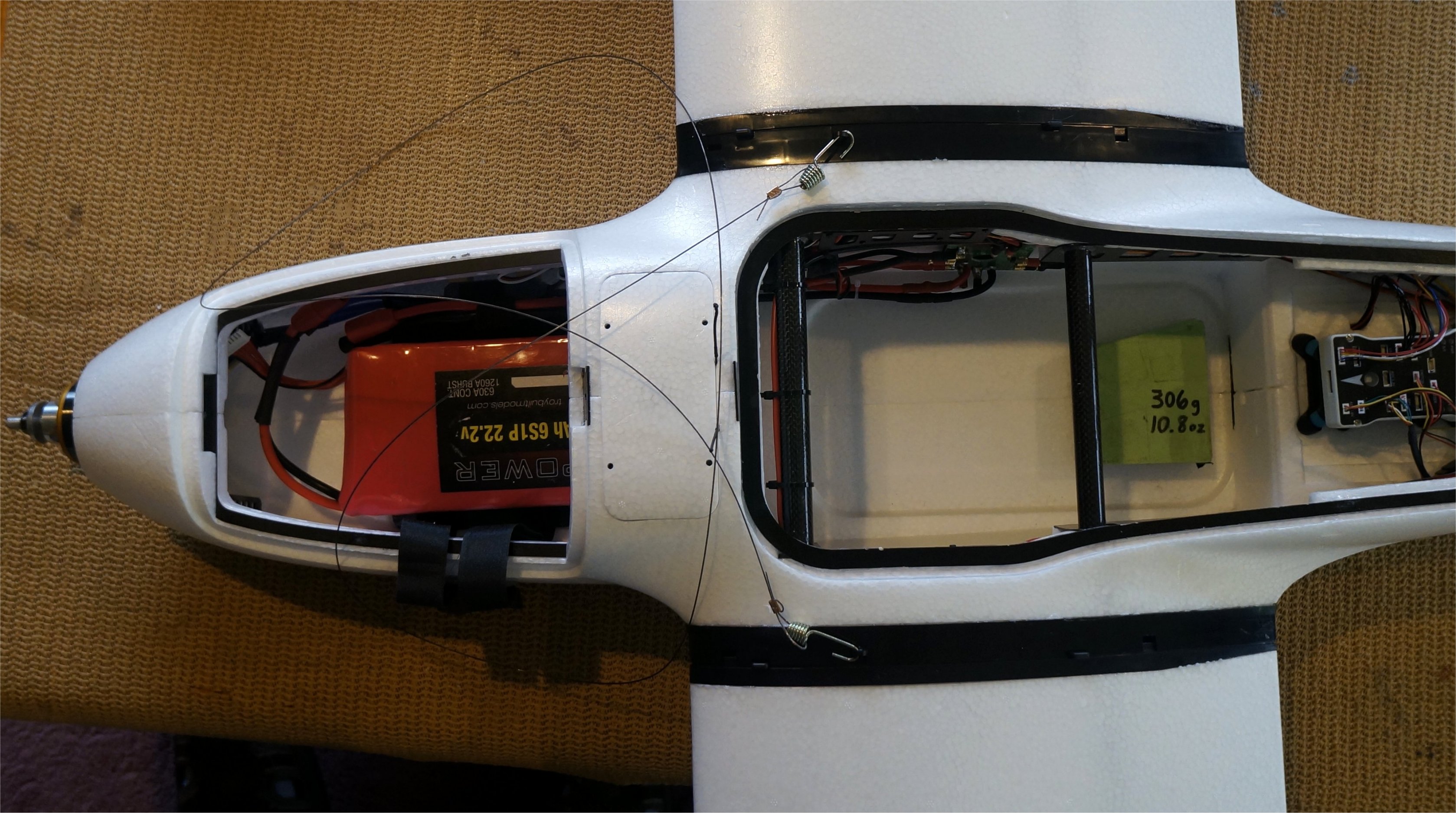
It was time to check the balance so I first created a lift line using 60lb Teflon coated fishing line and some metal hooks from one of my 100 bungee cords. The hooks fit perfectly into the eyelets on the Fighter. This was another nice design feature by MFE.
Using a 10.8oz (306g) payload, my Fighter balanced perfectly with the 5.3lb (2.4kg) 6s 21AH pack as shown. I haven’t measured the all up weight yet so we’ll see how close it is to the estimated 16lbs.
1 Like
Looking good Greg. Couple of questions:
-
Do you plan on taping or gluing the underwing foam panels that cover the wiring channels?
-
Do the wings still fit in the box with the hover booms on? IIRC it was a pretty snug fit.
-
What reference surface are you using to gauge “level” when doing the balance test?
Cheers,
Christian
Hi Christian,
I glued those in place. I can’t remember if I used Foam Tac or the Chinese glue…probably the latter. The channel is huge with no obstructions.
Not sure yet but I suspect they do. I’ll let you know…
That’s a good question. My guess was to call sitting on the foam pads as level. I’ll have more on that next week.
Cheers!
1 Like
Greetings All! we have most of our parts sourced for a build except for the VTOL and Cruise ESC’s, motors, and props. I tried to place an order with AliExpress for the recommended parts, but same result as everyone else, my order was cancelled. As a result we are in the hunt for these items…Any one found a source that can ship the recommended motors/esc’s or found suitable replacements?
One thing that we have been internally discussing is just using 6s power for both VTOL and Cruse propulsion. The VTOL motors and ESC’s in the kit are spec’ed for 6s, and the Cruise motor and ESC is spec’ed for 12s. With these equipment we would need a voltage stepdown to power the VTOL components. Anyone considering using a 6s Cruise motor as well that has sufficient thrust? We would need a higher amp esc, but it would remove the need to step down voltage for the VTOL components.
1 Like
I believe Greg is running a full 6s power system.
I will need 12s for secondary sensors so running 6s for VTOL will require a step down voltage regulator in my case.
I’m digging into T-Motor options… the MFE spec for VTOL is 4@ 170kV and the cruise motor is 210kV. There are many more options in 6s but there might be a few 12s that will be close enough to work.
I am open to the following power/propulsion combos:
a) 12s primary power with 12s Cruise/VTOL
b) 12s primary power with 12s Cruise and step down voltage for 6s VTOL
c) 12s primary power with step down voltage for 6s Cruise/VTOL
The main consideration between 12s vs. 6s is the lower Amps due to higher supply voltage. With lower Amps I believe you end up with a better longevity of the system as there is less heat generated.
Hi,
MFE has specified power systems for a 6s setup in post #26 below.
My 6s power system is just below that in post #27.
Cheers!
1 Like
FIT-RS
You can email the MakeFlyEasy store directly at 1641637133@qq.com.
Tell them what you want to order and they will set up the order for you.
I paid $210 for shipping and $61 for import duties. Parts arrived via DHL/USPS in about 2 weeks.
2 Likes
Thanks Tim, just sent an inquiry to the address…lets see if they can proceed with order.
I have some weights on my model. It came out pretty close to my guesstimate of 16lbs without payload.
- RTF with Payload @ 16.45lbs (7.45kg)
- Fuselage = 3.0lbs (1.36kg)
- VTOL Wing = 3.2lbs (1.45kg)
- Tail = 1.0lb (0.45kg)
- 6s 21AH LiPo = 5.3lbs (2.40)
- Payload = 0.75lb (0.34kg)
2 Likes
Thanks Greg, we still want the payload capacity of the 12s system so I think your VTOL equipment will be a bit light for us. I see you ordered them from FoxTech…can you comment on them as a supplier? There are a couple other items I have been interested in purchasing from them, but I cannot find any reviews on them. If you prefer we can discuss out of this thread. Thanks for all your guidance with this kit!
Nice!
Did you go through with the hover test already?
Yes, I have ordered many times from FoxTech and had items shipped via DHL without any issue. They have unique items…not all of them are pricey.
Yes…posting video soon. ![]()
1 Like
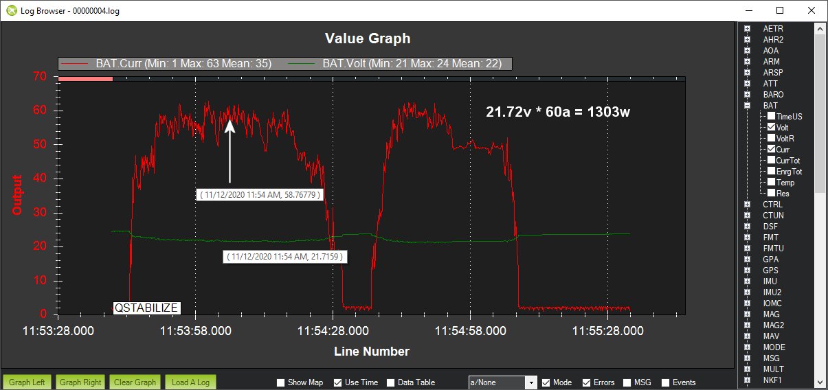
My initial hover testing of the MFE Fighter in my backyard was successful. I left it in QSTABILIZE mode because it was hovering in a small area with a canopy of branches overhead. If I have the opportunity, I will try to test the BARO and GPS sensors before the snow flies.
The weight of the plane was around 16.5lbs (7.5kg) with my 11oz. (0.34kg) payload. The payload was simply a weight that matched my Sony NEX 5n camera. It took about 1300 watts to hover or 15amps per ESC. I’m off to a good start!
3 Likes
Beauty!
Great to see. Nice work Greg.
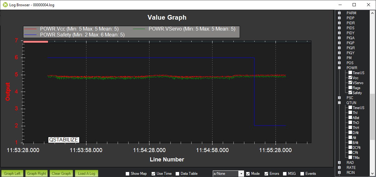
Thanks, Christian. The video was my actual first few hovers and motor spin ups with the props on so I am happy it worked good. It validates much of my setup. Note that my battery was not fully charged for the hover test. I think it had somewhere between 4.0 and 4.1 volts per cell on it.
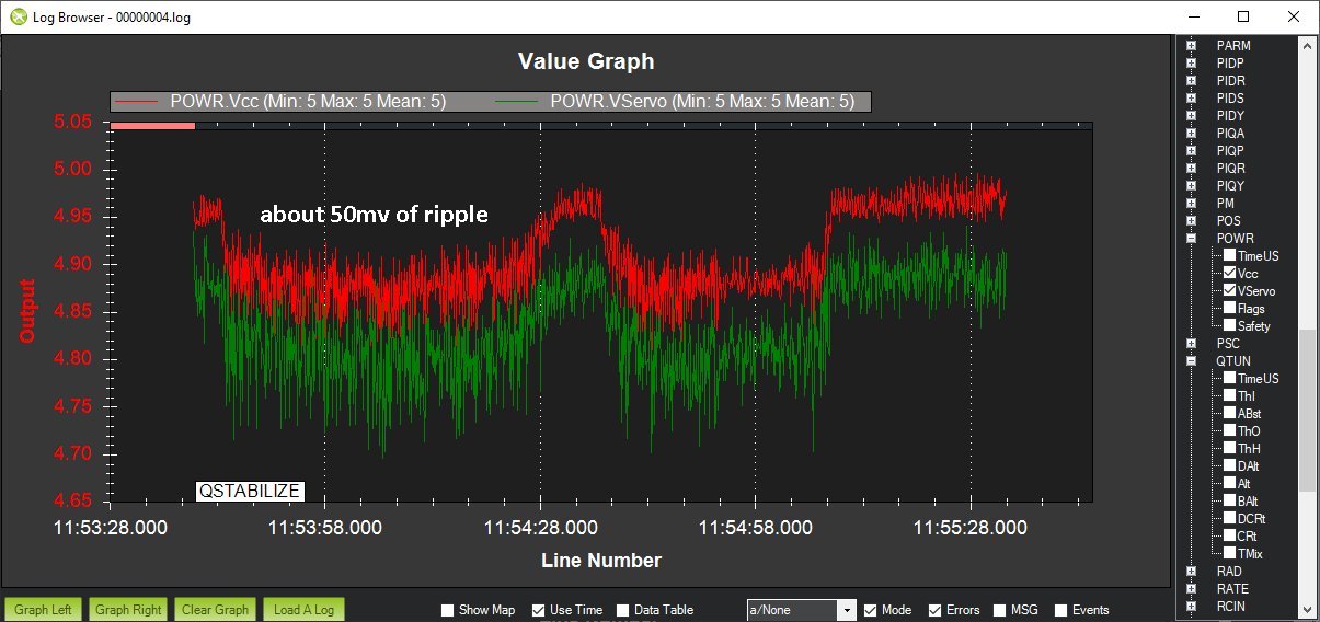
One issue I saw was excessive ripple on my graphs and narrowed it down to my servo rail which is supplied by a CC BEC. I pull out my Tektronix oscilloscope and saw that the Mauch 5v regulator looked good (even with the long cable to the Pixhawk) but the CC BEC 5v on the servo rail had about 50mv of ripple on it which showed up on the graphs. It was solved by plugging a 3300uF capacitor into the servo rail. I used a channel that only had the signal lead plugged in so it didn’t waste an output port. My next graphs should be much cleaner.
1 Like
@GregCovey - I have been out of commission for while just ordered from AliExpress. Dec 17 Delivery
What Lipos are you guys using? I am looking for maximum flight time and also what T-Motors are recommended and ESCs’
Thanks for help in advance.
Asim,
You should probably read the thread again. You can use either a 12s or 6s power system. MFE has specified power systems for a 6s setup in post #26 (as shown below). The User Manual (linked in post #19) has the 12s power system ratings. I posted them again in #22.
My 6s power system is just below that in post #27. My battery in post #31.
Some food for thought. If my 6s power system can hover the plane on only 15amps per motor, why would you ever need to use a 12s 60A ESC?
Cheers!
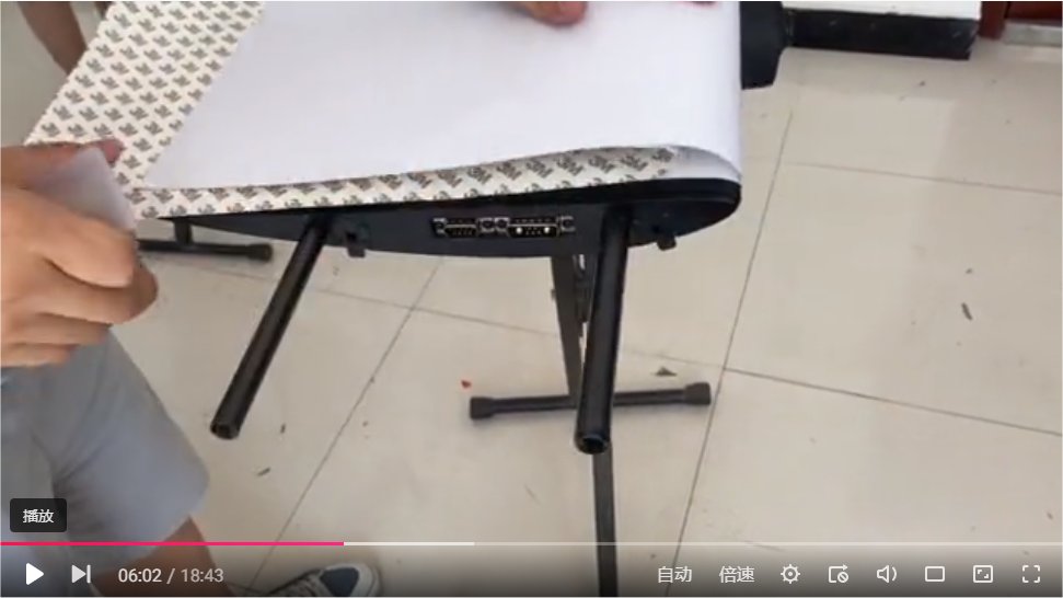
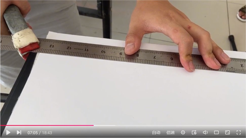
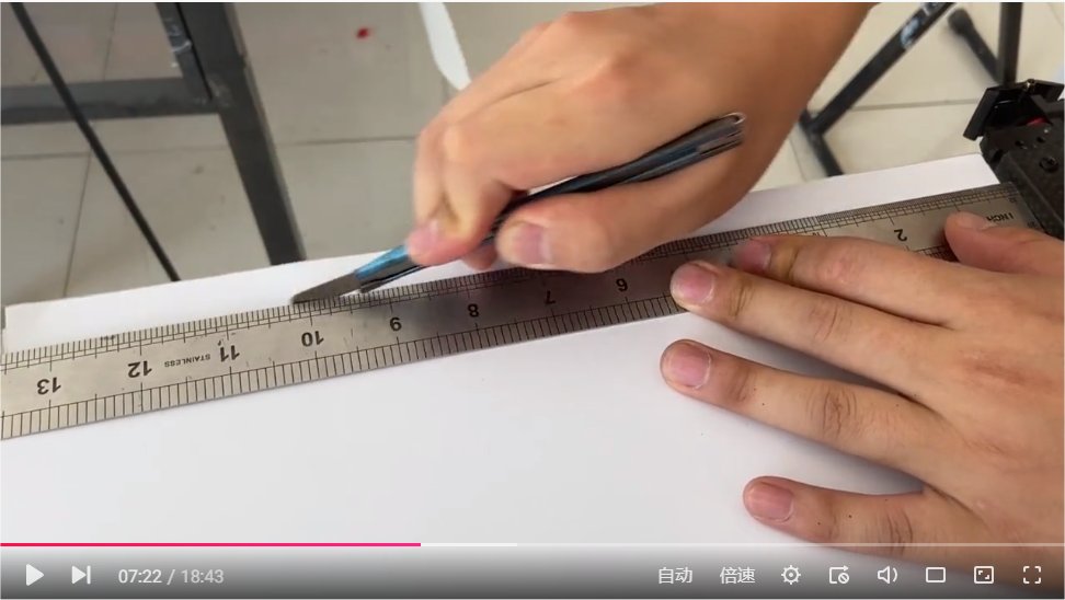
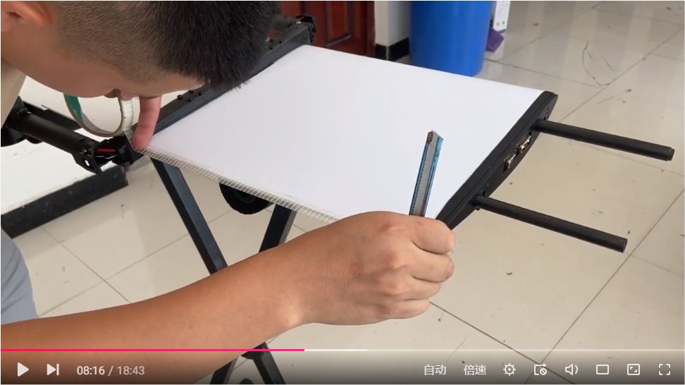
I was about to add some decals to my wing when I realized that I missed the step of adding the “fixing film” in the Debugging Guide 3 video. I mostly followed the video installation, but at the trailing ends of the 3M Mylar film, I changed my technique.
On my previous Freeman VTOL build, I noticed that dirt would get trapped in the strapping tape used to cover the aft end of the 3M Mylar film so I simply started with a 1/4" overlap and then wrapped the Mylar around the wing. In this manner, only one side needed to be trimmed and I just squeezed the two sides together. The sticky glue on this 3M Mylar will not come off when the two sticky sides are pressed together and the finished look was a bit cleaner.

1 Like
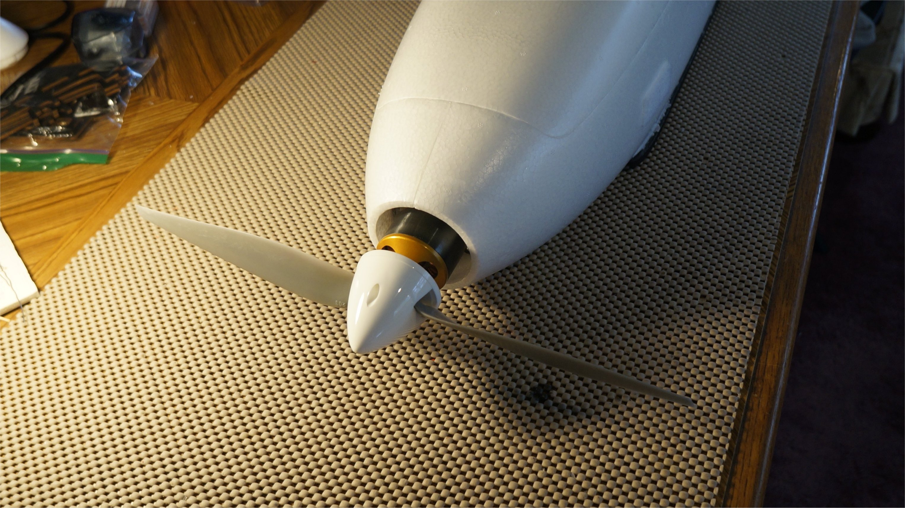
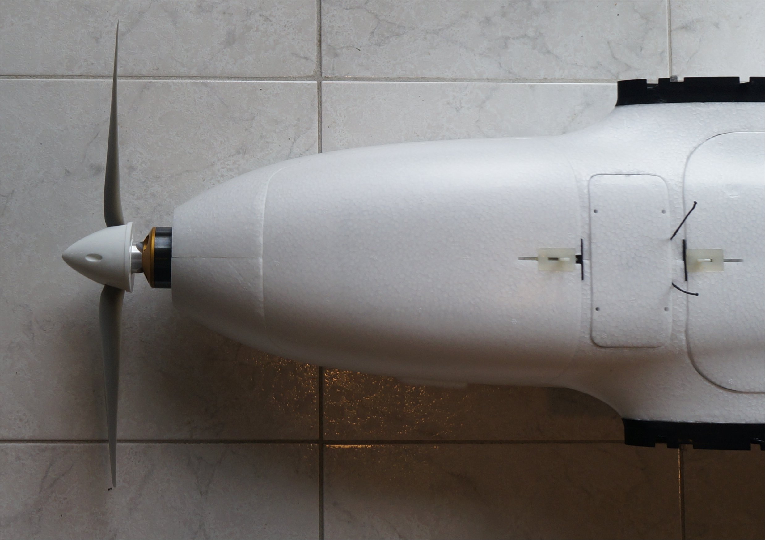
Before re-testing the box fit, I installed the APC 15x8 e-prop on my AXI 4120/18 (515kv) motor with a white spinner. The 1500 watt forward flight power system should fly the Fighter nicely, using partial throttle for cruising around while mapping.
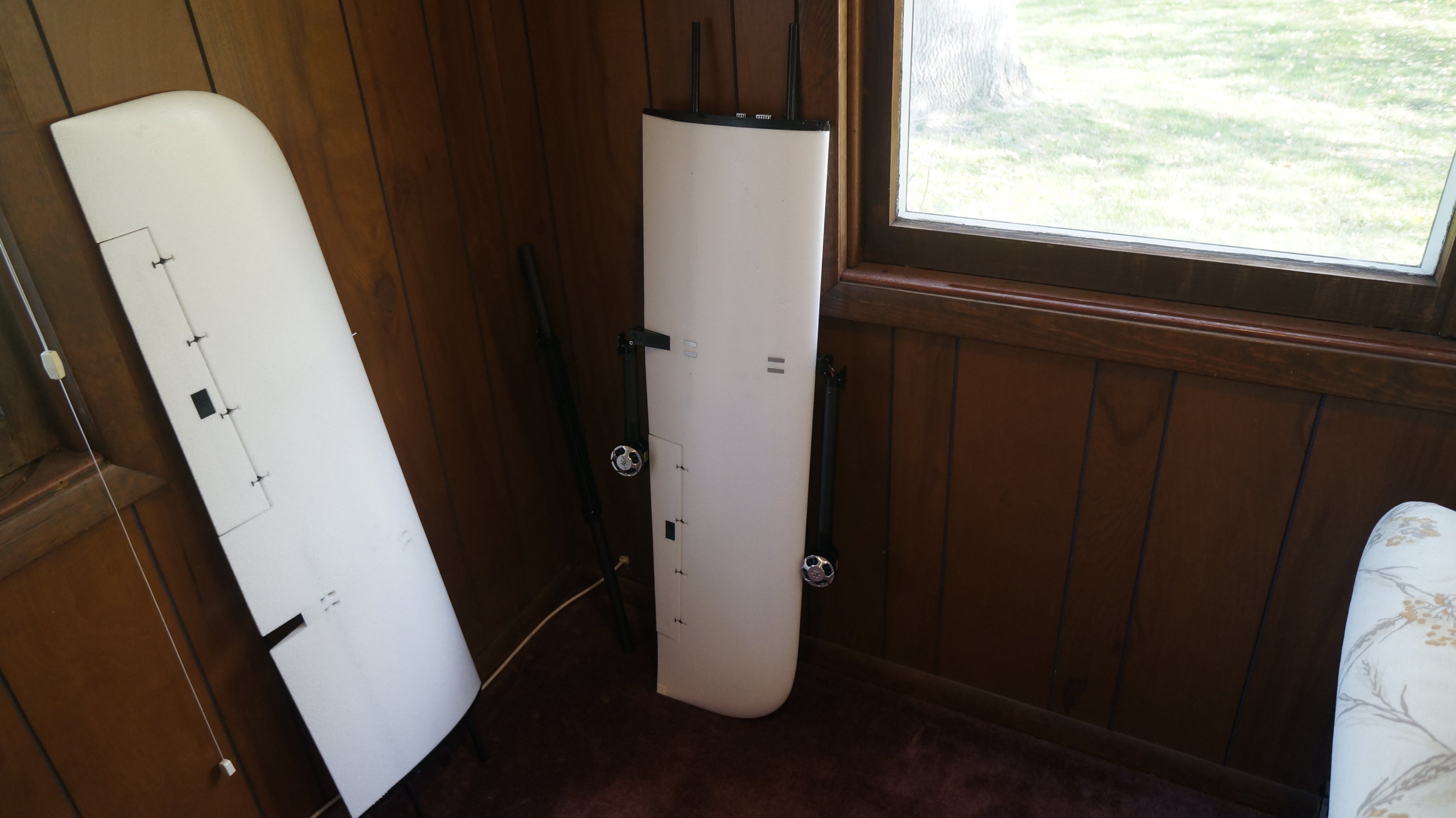
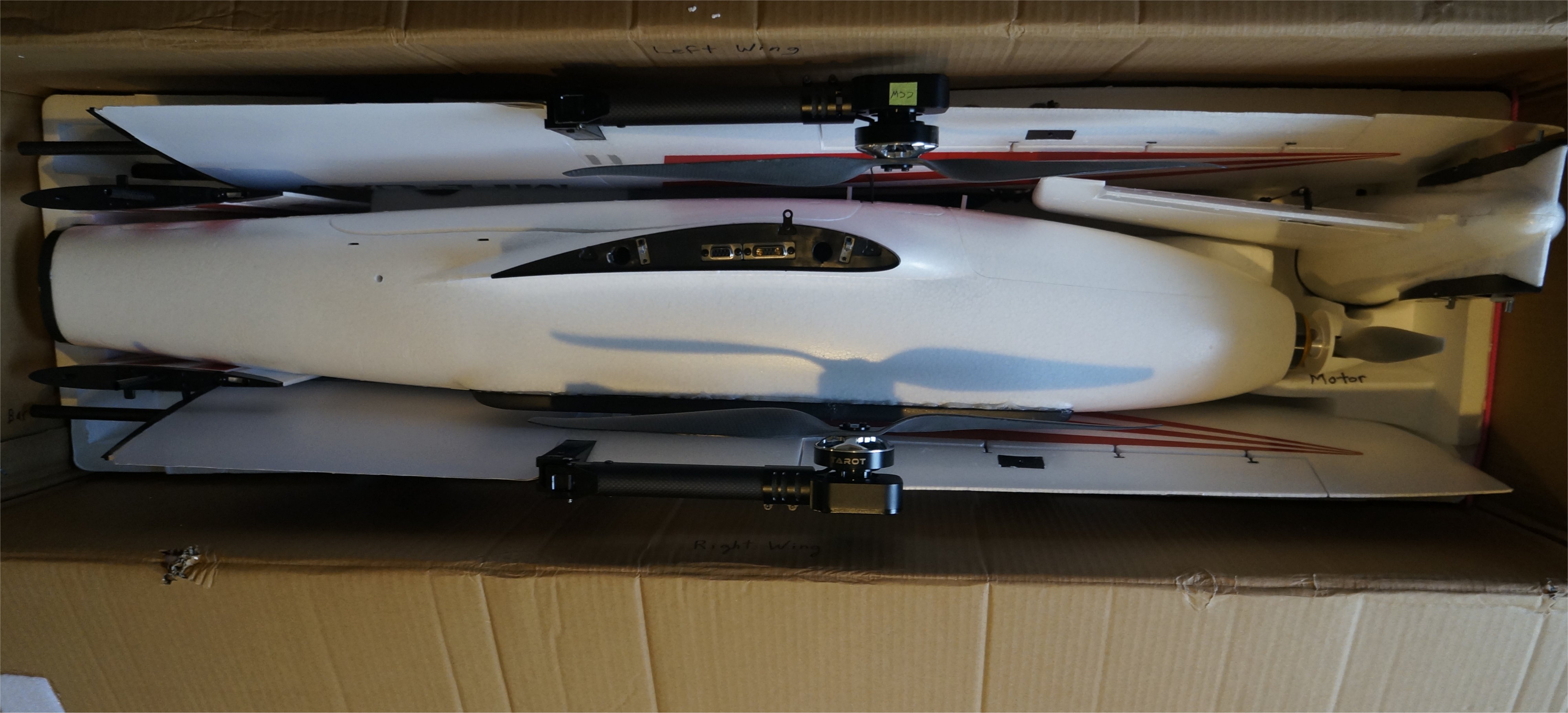
Everything still fit fine in the box even with the 5 props installed.
1 Like