Hi Greg, you that these fake pixhawks have some problems with internal compass and IMU as with arduplane 4.x.x ? I recommend you using matek instead if you have any problem with the „boxed„ ones.
Tim,
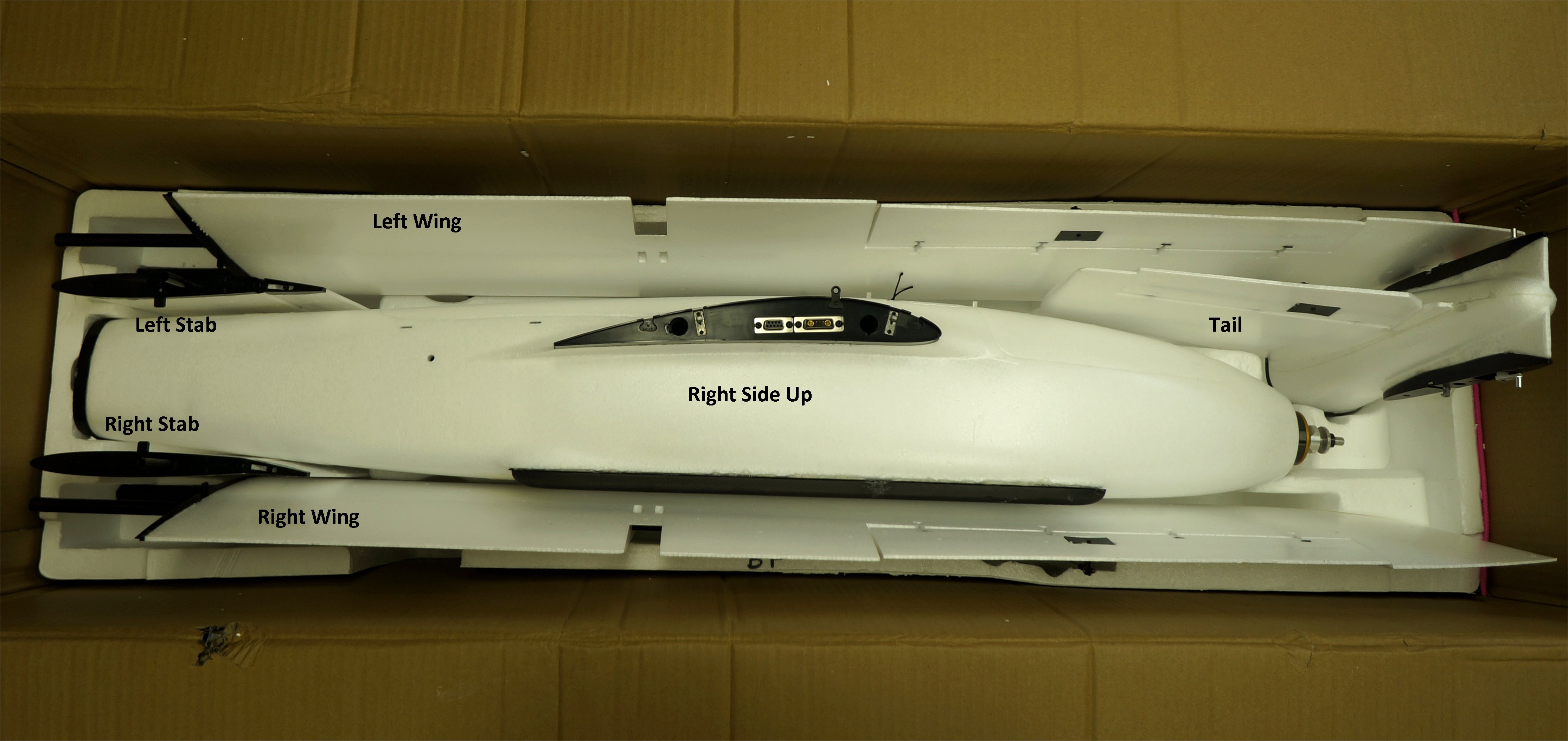
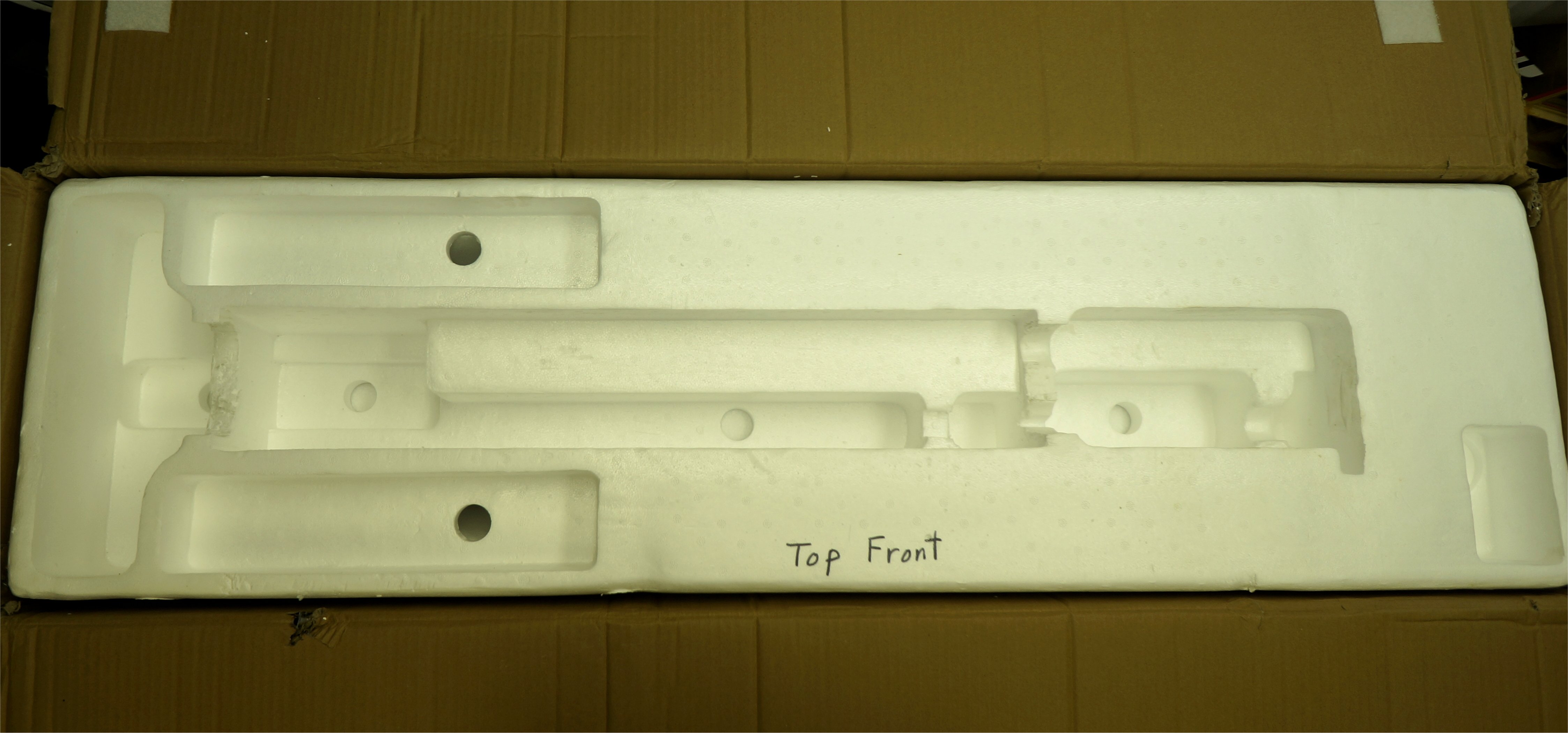
I took everything out of the box, foam included and found only one. Even bashed the box around to listen for lost screws… Nothing. still short 3 screws.
Website states IPX3. IPX3 : Can take water sprays of up to 60°. Obviously the electronics would be the main concern in keeping them dry and not letting them overheat. I’ve never flown in rain intentionally. The cabin is probably fine, but the hovering motors and ESC could be the most susceptible to water from above.
Greg, yes good tip!
I might try to gut a large cooler and reuse the packing foam inside of it. If it works out, it will be a more permanent solution and potentially waterproof. 
Hi Michael,
I am not aware of this issue. Do you have a link? I don’t use the internal compass anyway, only the external compass on the GPS puck.
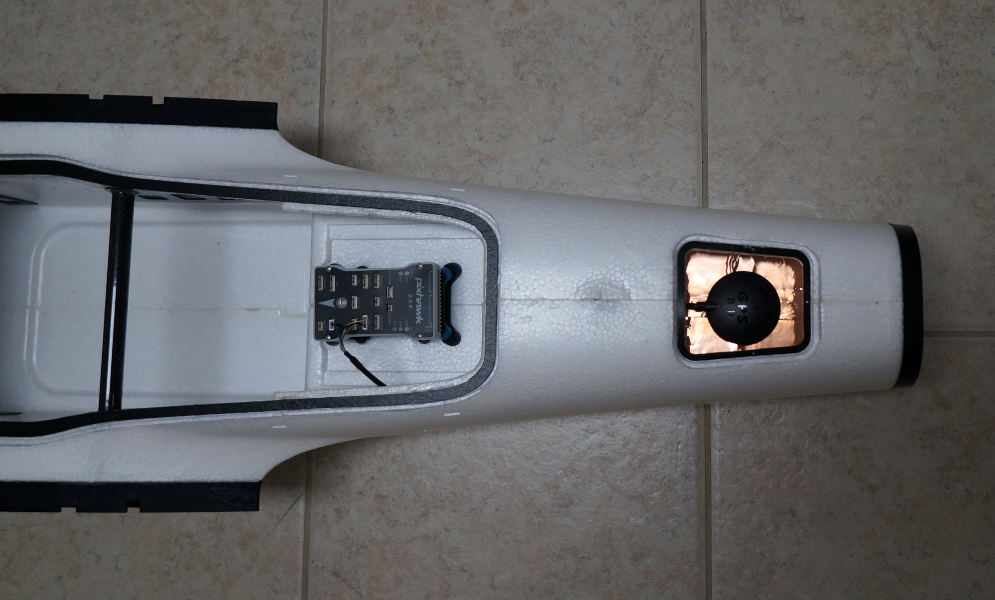
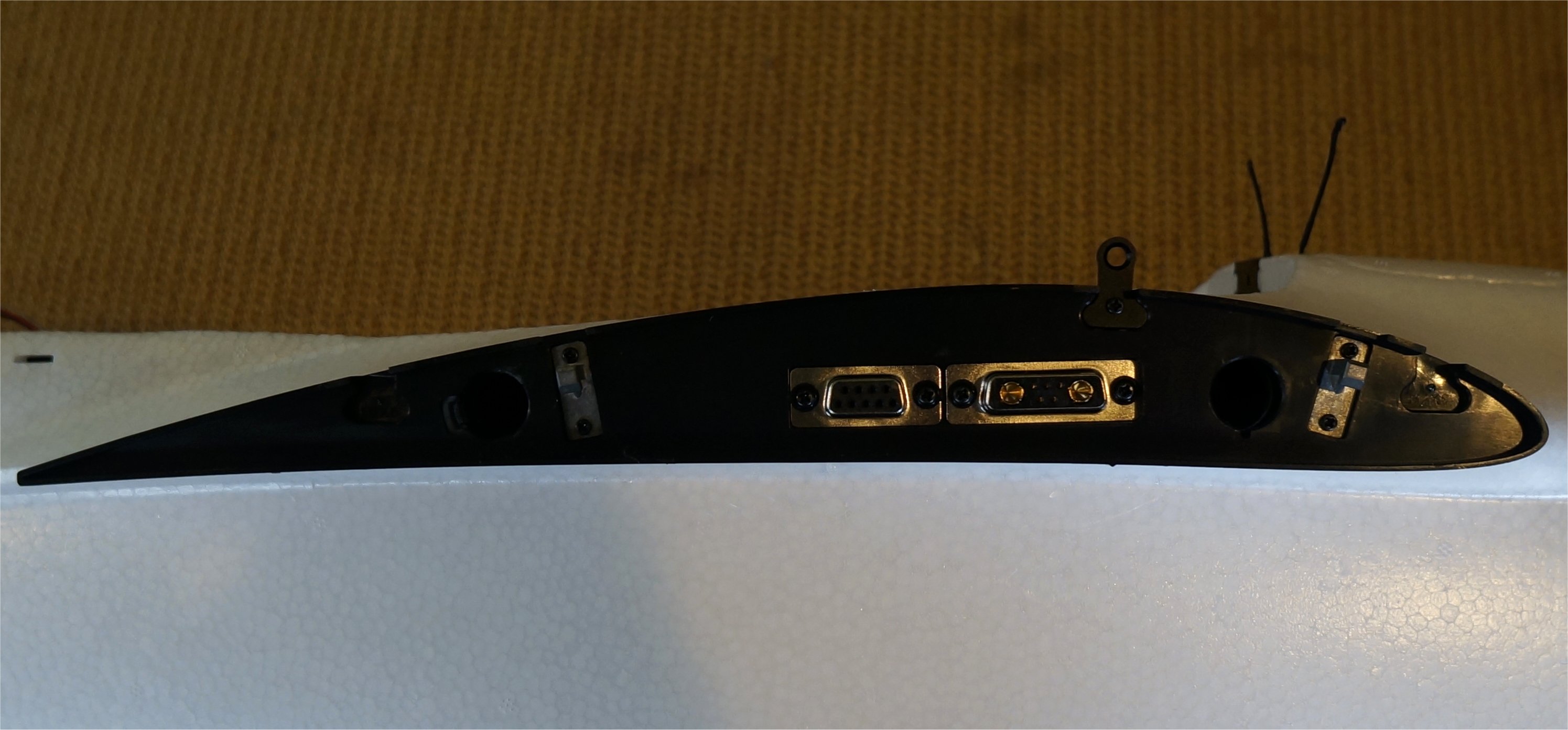
I might as well post my GPS puck mounting on the Fighter. I used the “clean” area designed for the puck at the tail end of the fuselage. I laid down a layer of copper tape to cover the servo wires from the rear connector and create a barrier from the telemetry unit I have in the chute bay below. This helps keep RF away from the sensitive GPS receiver. I noticed the screws were magnetized so I taped the cover on for now using white duct tape. I may buy some M2 nylon screws but I have used this tape before with success. I also use it to tape the chute hatch closed like I did on the Freeman VTOL.
Greg and all,
First thing, I appreciate you taking the time to support this build thread on the Fighter VTOL. It is very helpful.
About the cheap Pixhawks, I have extensive background and experience with over 300 Pixhawk 2.4.8 plus around 20 Pixhawk Cube Black and Blue installations. Eight years ago I developed and taught for seven years a community college two year associates degree UAS program where the students were required to build an Ardupilot Pixhawk based quadcopter and fixed wing aircraft. In the first three years of the program, I let the students buy the pixhawk from any source. They were very good at finding the cheapest source available for the Pixhawk and GPS. The students had so many crashes and fly aways that I banned buying cheap Pixhawks. I never had problems with 20 school aircraft that had brand name Pixhawks from mainstream vendors. I gave them a purchase list of electronics from approved vendors for the Pixhawk and electronic accessories. They were required to purchase only from the approved vendor list. This eliminated the recurring problem of Pixhawk hardware failures. I now support a university UAS flight program where they build training and research aircraft that are Pixhawk 2.4.8 based.They have had only one flight controller issue. After two years of active flight training and flying missions, one flight controller is having accelerometer issues and needs to be replaced. Sometimes it costs a lot of money to cut corners and go cheap. In my opinion, a lost aircraft is not worth saving USD $100 on a flight controller.
2 Likes
Hi Dennis,
I haven’t had many Pixhawk failures in projects going back 6-1/2 years now. When the Pixhawk clones first came out, we decided they were all built in China anyway. I was in on the initial Pixhawk testing back when we were all using APM v2.6 boards or recoding our Multiwii MEGA boards. Comparing the Pixhawk 1 to the Cubes is like comparing “apples to oranges”. The Cubes have much better protection from their environment but at a cost ratio of 5:1 or more if you change colors.
That being said, if I was building a commercial vehicle, I would use a cube but the Pixhawk 1s are fine for my hobby use. By properly protecting them from vibrations and temperature change, they really do work well. Granted, I don’t fly in extreme temperature or weather conditions. The days are typically calm to 10mph winds with temperatures from 60-80 degrees F. Fun hobby flying weather. 
Here’s my first VTOL mapper from 4 years ago. It still flies great! Before that, we used quadcopters and hexicopters but I lost interest in the pure hovering machines. Much of what we buy is based upon our budget so I try to keep the cost down when possible for my R/C hobby projects.
Cheers!
1 Like
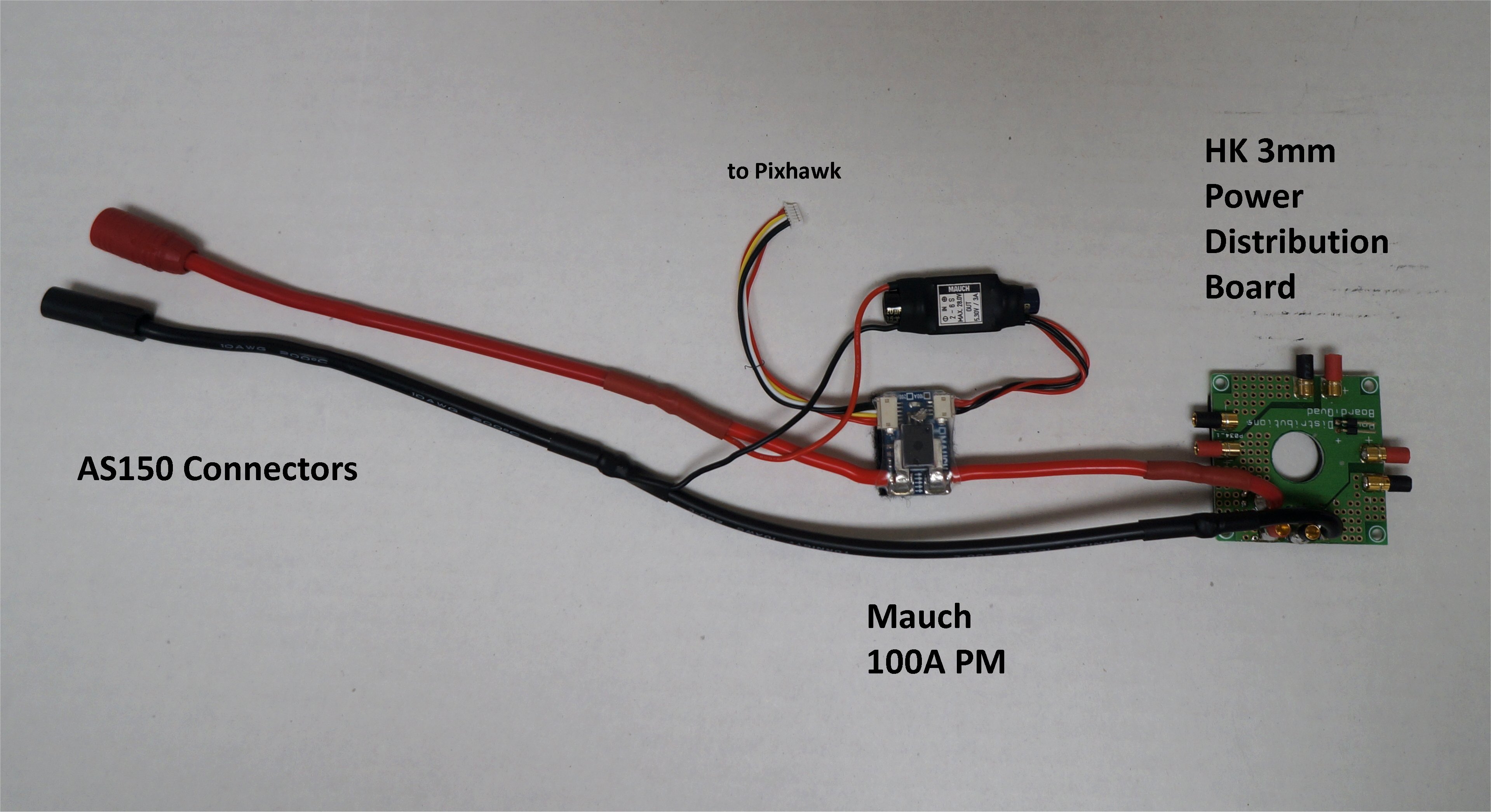
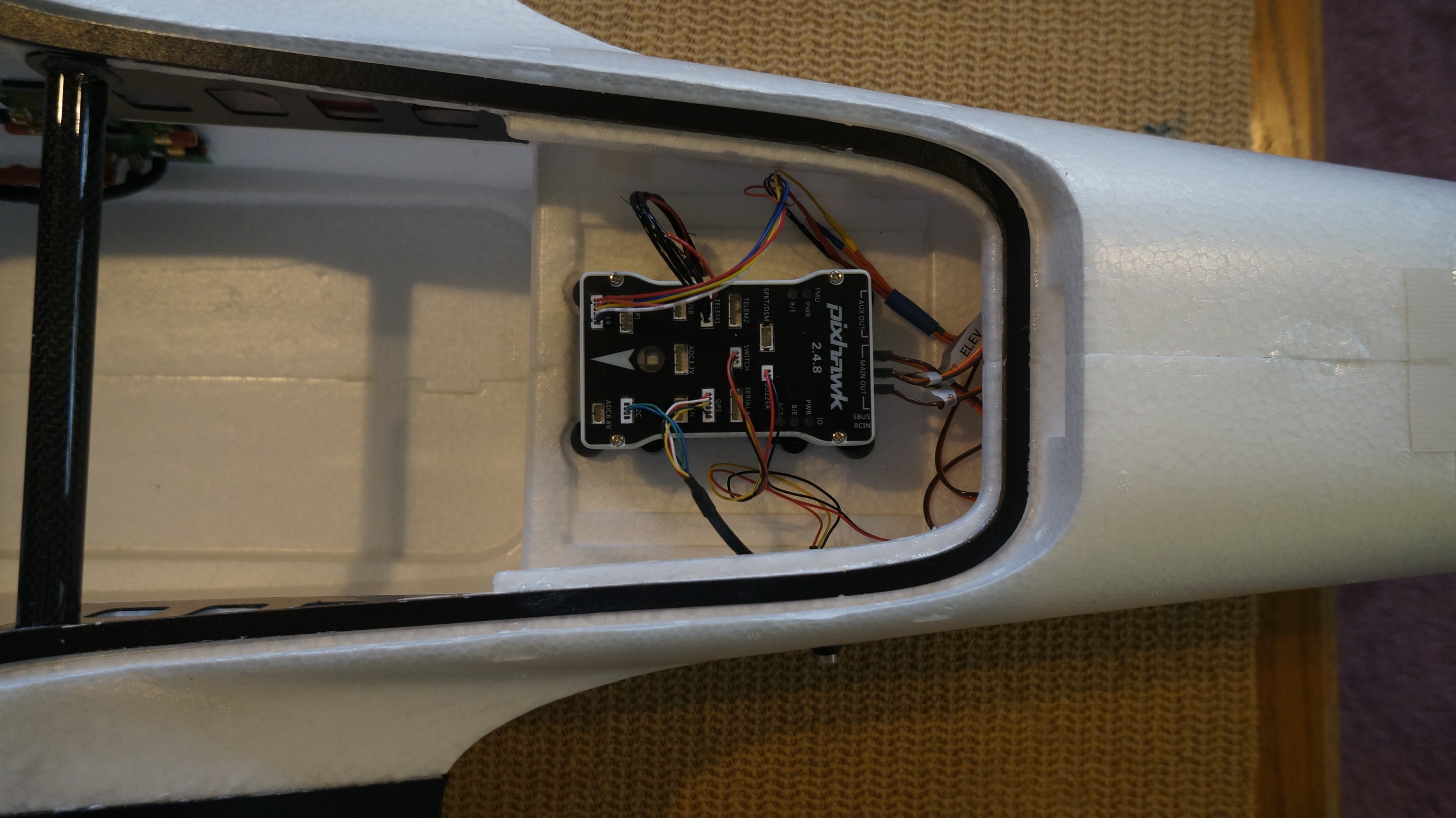
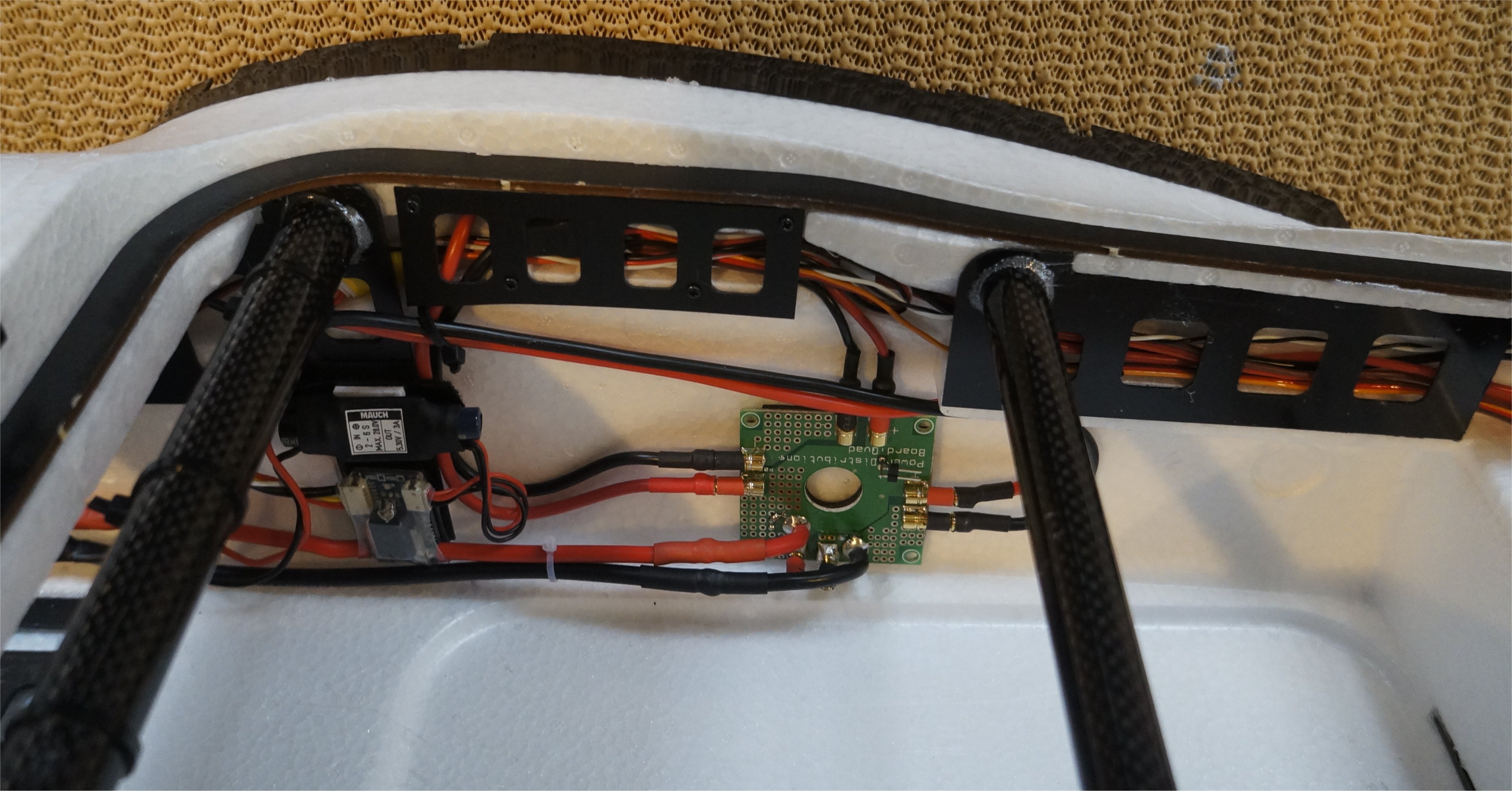
I was still not ready to wire up my wing connectors (mental block) so I decided to start my power wiring. These components, and the Pixhawk v2.4.8 above came from my re-purposed FX-79 VTOL. The VTOL flew fine but I am now hooked on new designs like the MTD Nimbus, an MFE products that simply snap together without tools or cables to connect. My BEV FireFLY6 and E-flite Opterra come close but these new designs have taken it to the next step for ease of assembly and transportation.
The Hobby King 3mm Quadcopter PDB has worked well for me in many projects, including the Nimbus and Freeman, so I decided to keep using it on the Fighter. I need to create a 6-pin extension to reach the Pixhawk PM connector but I had all the parts. I love the wire channeling built into the Fighter! There is another removeable piece that screws over the wing socket area that I have not put on yet.
It’s always a big moment for the initial powering of the flight controller (a.k.a. blow-up test) so I was delighted when I saw the LEDs and heard the musical dance on my Pixhawk v2.4.8. Here is my initial param file with the AS sensor disabled. My initial hover testing will not use it.
GregsFighter3.param (20.6 KB)
1 Like
Would you mind sharing your preferred vendor list.
Thanks.
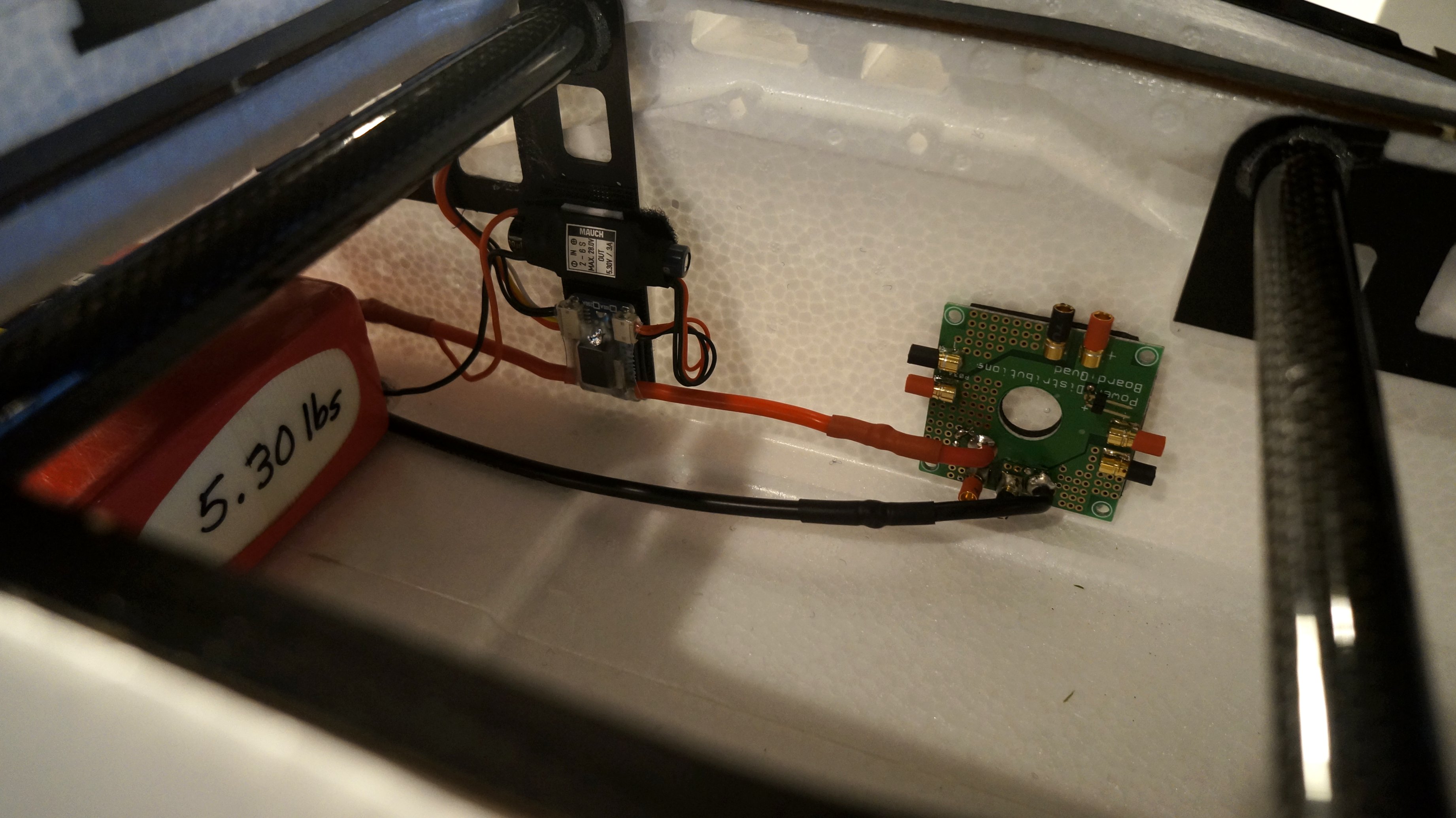
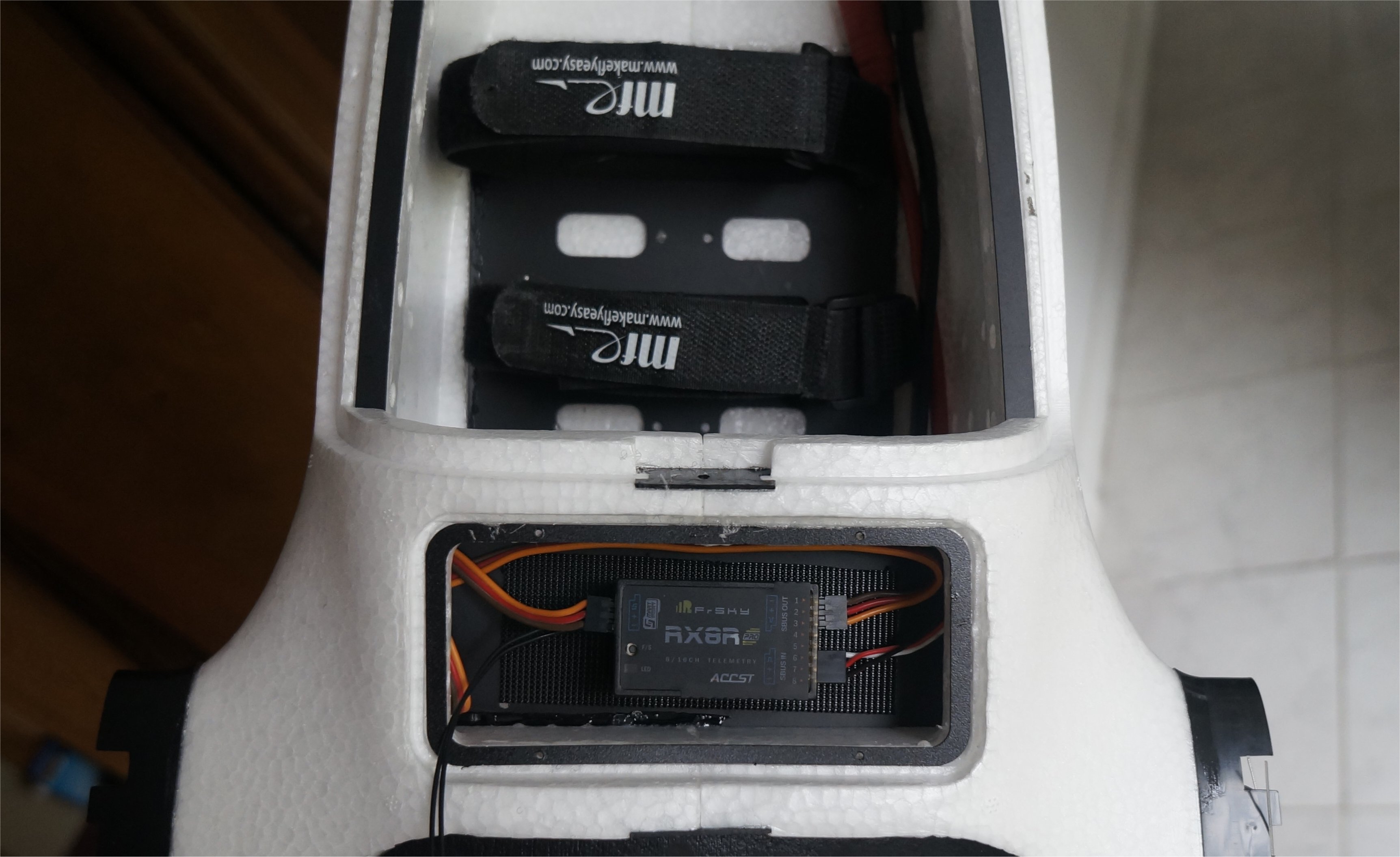
I added the battery straps which were supplied with the kit. They were still too long even for my 6s 21AH pack so I doubled up an area of several inches. I might suggest that these straps be placed before gluing the plate down as they were difficult to pull through. I cut a hole in the tip of the strap and ran a twist tie through it so I could more easily pull the strap through the slots. I’ll add some Velcro to the bottom plate to keep the battery from sliding.
The air flow from the open nose goes right over the battery pack.

1 Like
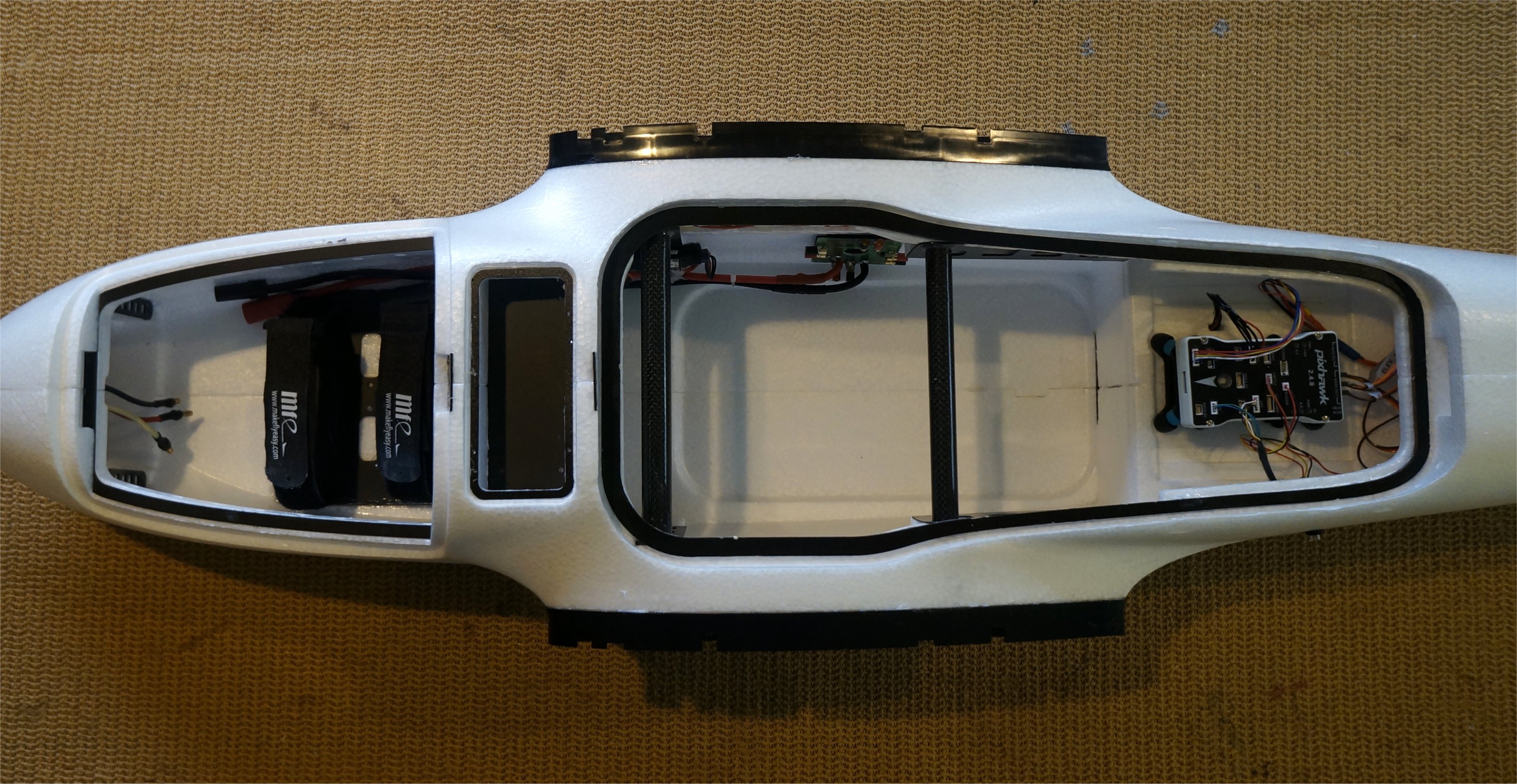
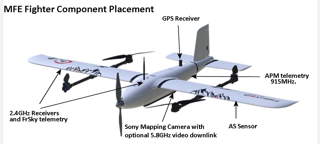
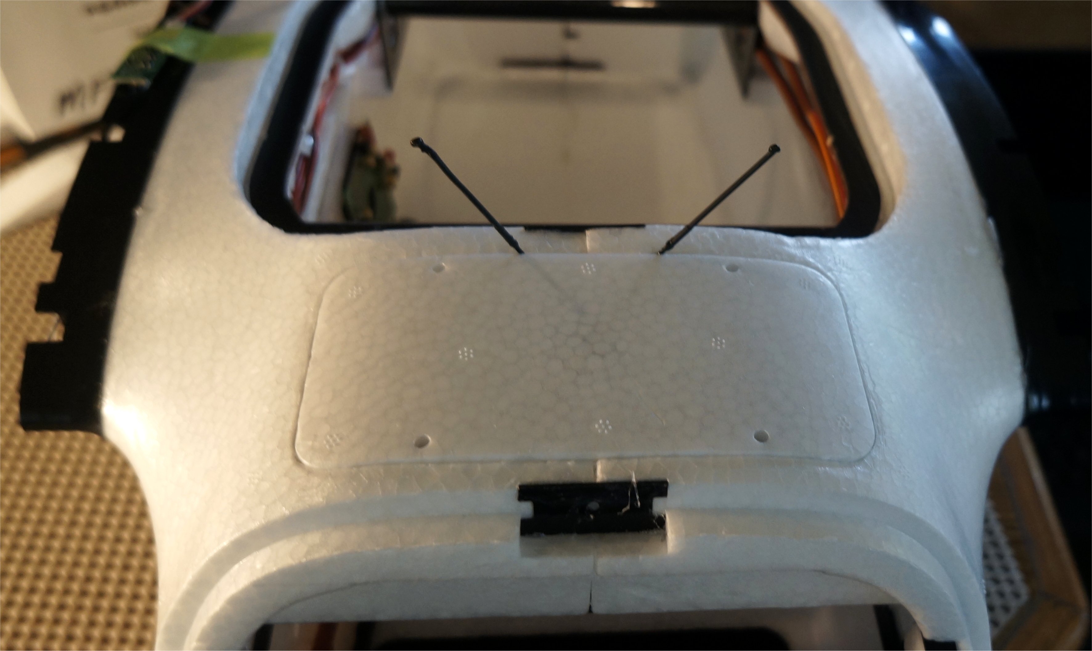
I created a component placement diagram for all the receiver and transmitter positions I intend to put in the Fighter. For the FrSky RX8R redundant receiver, the primary receiver is mounted in the box between the two hatches with the antennas sticking up. The secondary XM+ receiver on the right wing will have its antennas facing down at 90 degrees from the RX8R antennas.
I found some M2 nylon screws at Banggood. You get 100 of them for $4 and only $0.18 shipping. I’ll use these to secure the smaller hatches over the GPS and R/C receivers.
1 Like
Greg,
Did you end up getting one of the FrSky Redundancy Buses?
For the wing motor ESC’s power, I was considering using one of the HobbyKing power dist lite boards to split power at the junction where the MFE wing boards would sit. HK only has the lite version, however the specs are the same other than the connector size which I’ll just resolder larger bullets. Looks like the servo connections are just a passthrough on the wing board anyhow.
Hi Christian,
I decided not to get the FrSky Redundancy Bus after reading too many complicated issue posts on the RC Groups Radios forum. Instead, the RX8R works out of the box with most other FrSky SBUS receivers and I get power supply redundancy through the Pixhawk Servo Rail. Granted, this doesn’t solve my redundancy issue with the main battery disconnecting on a crash but I’ll keep working on that. I’ll be adding the ViFly Finder 2 to my Fighter and may end up getting the FrSky Redundancy Bus just to use the dual battery supply for the receiver.
I see that HK no longer sells the 3mm quadcopter PDB but you might also look at this 3mm Octocopter PDB at Banggood. They have several different PDBs available.
Cheers!
1 Like
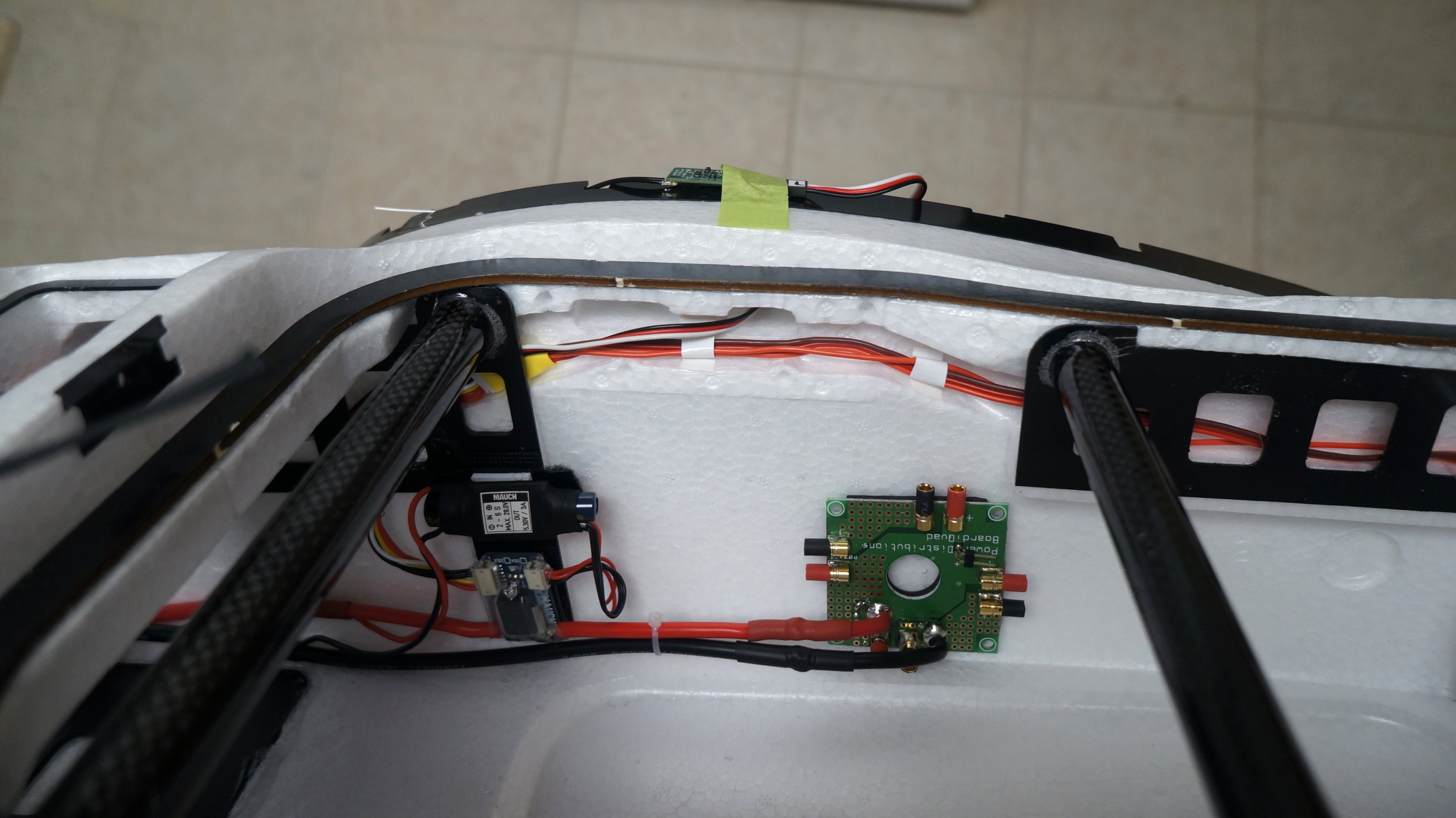
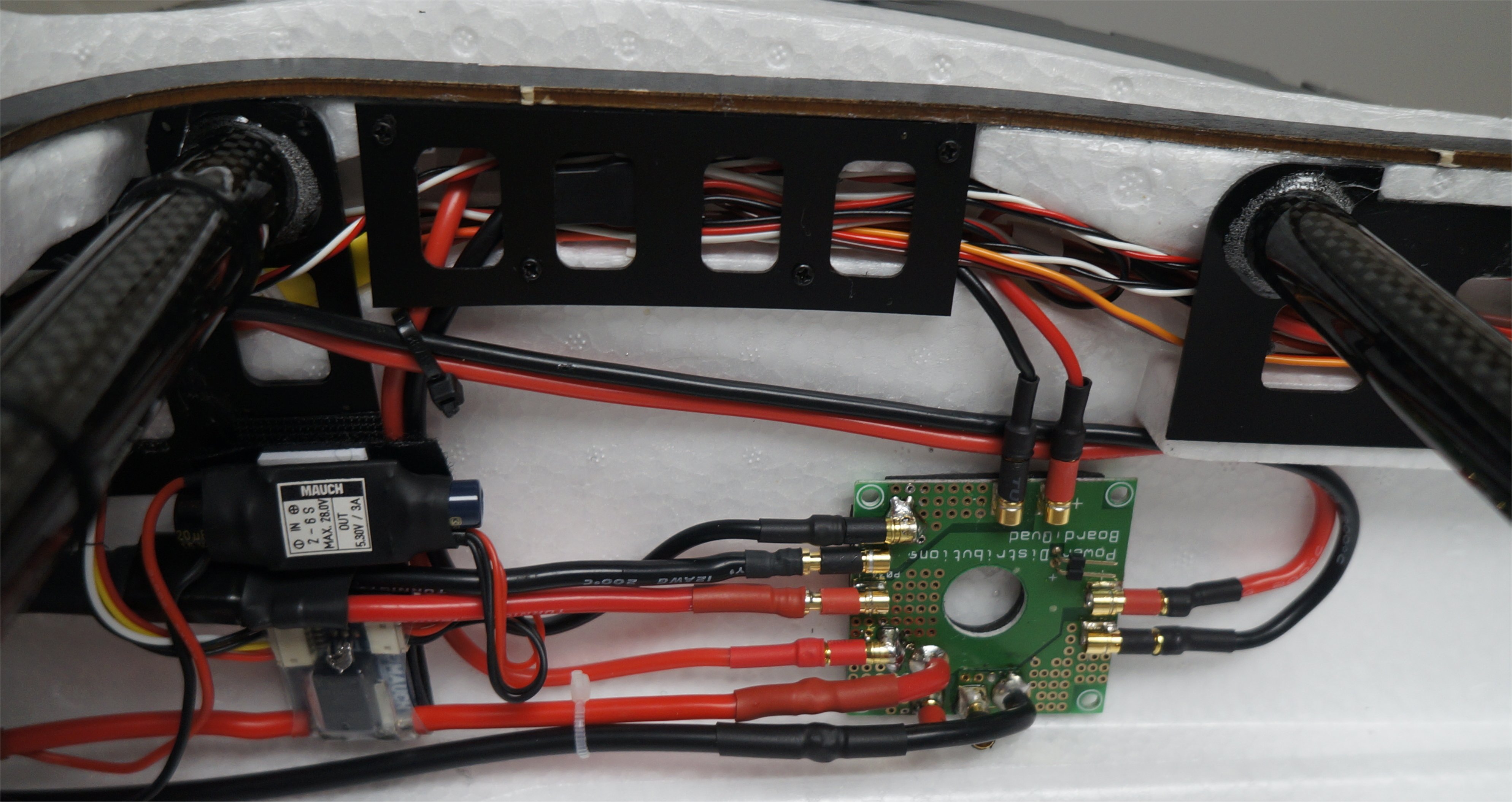
I used a CC BEC programmed for 5v to power my servo rail. This also becomes my backup power to the Mauch Power Module for the Pixhawk. The 5.7v Zener diode conditions the line for back-up power so the voltage spikes never exceed 5.7v. See the Powering the Pixhawk section of the WiKi for details.
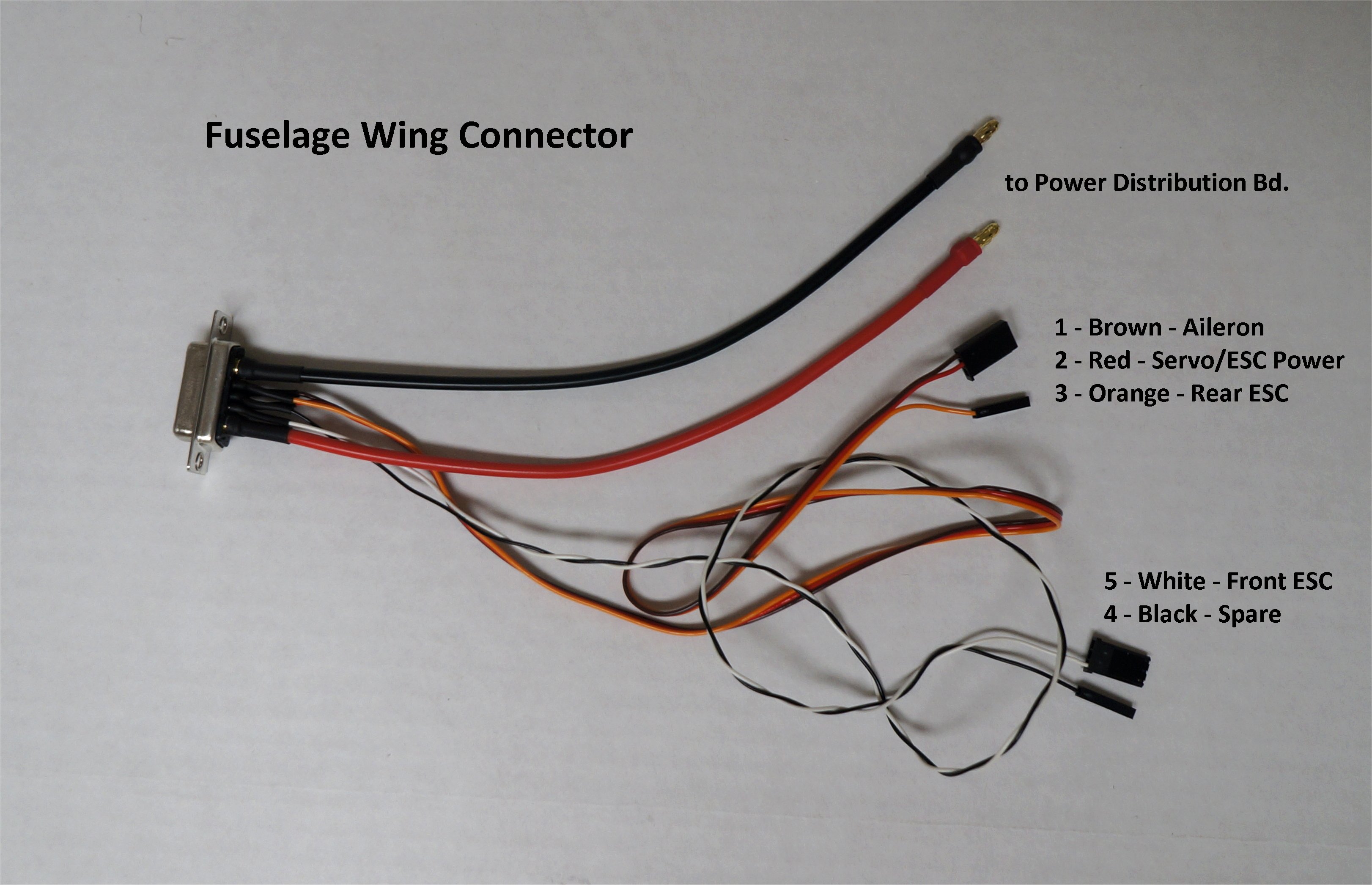
I started on my wing connectors by wiring the right wing fuselage connector. All the wires were supplied with the kit except for the white and black twisted pair. These were old Red/White/Black twisted pair servo extensions I had on-hand from FMA Direct. I removed the red wire and it allowed me too have different colors for all 5 wires. The orange and black wires were put into single pin servo connectors to easily plug into the Pixhawk.

1 Like
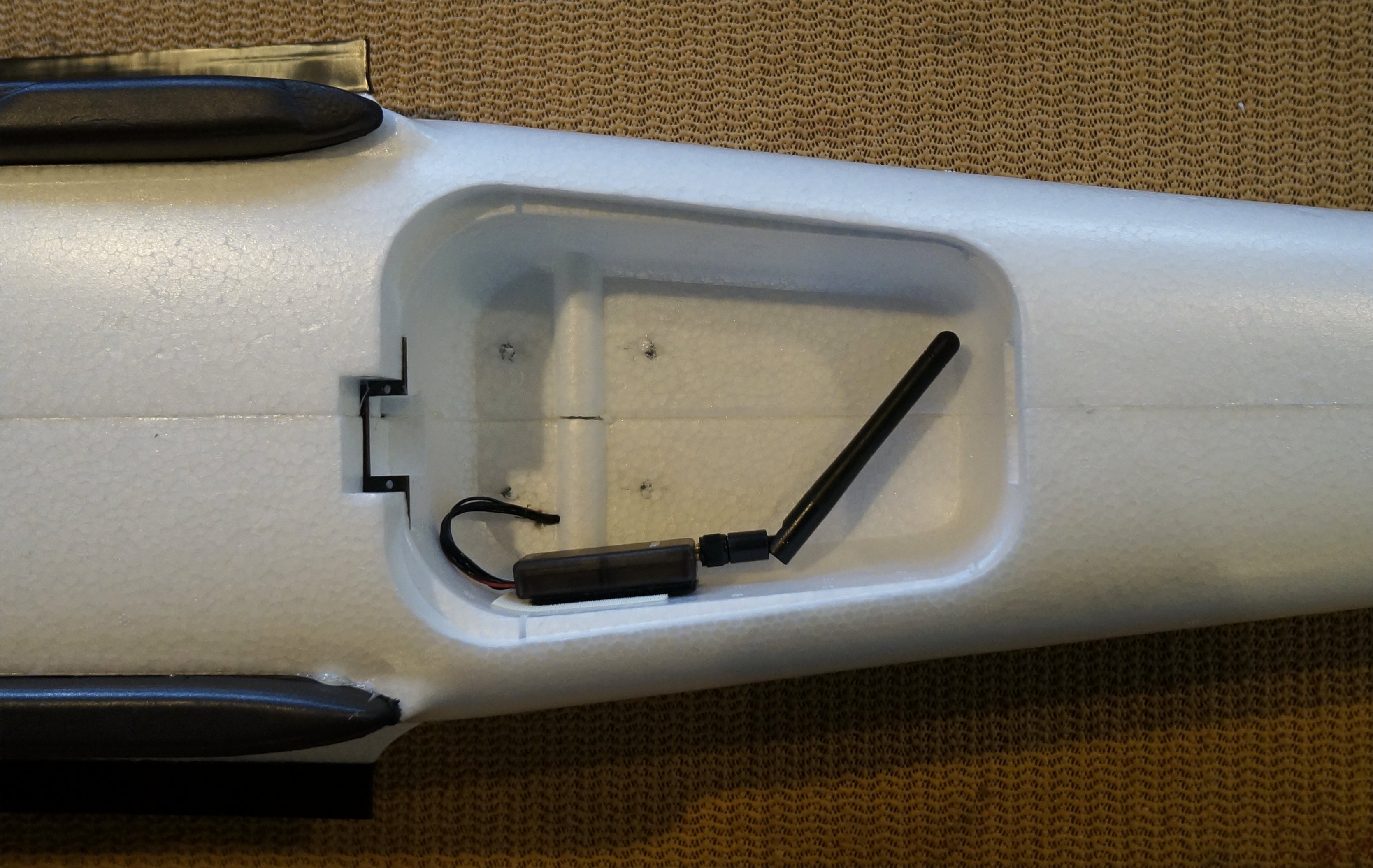
I initially mounted the 3DR telemetry unit in the chute bay as shown to get my wireless telemetry link to Mission Planner. This worked well for me on the MFE Freeman VTOL. I may change it down the road or swap it for a spare RFD900 unit because I often use QGC on my tablet with a smaller 3DR telemetry unit.
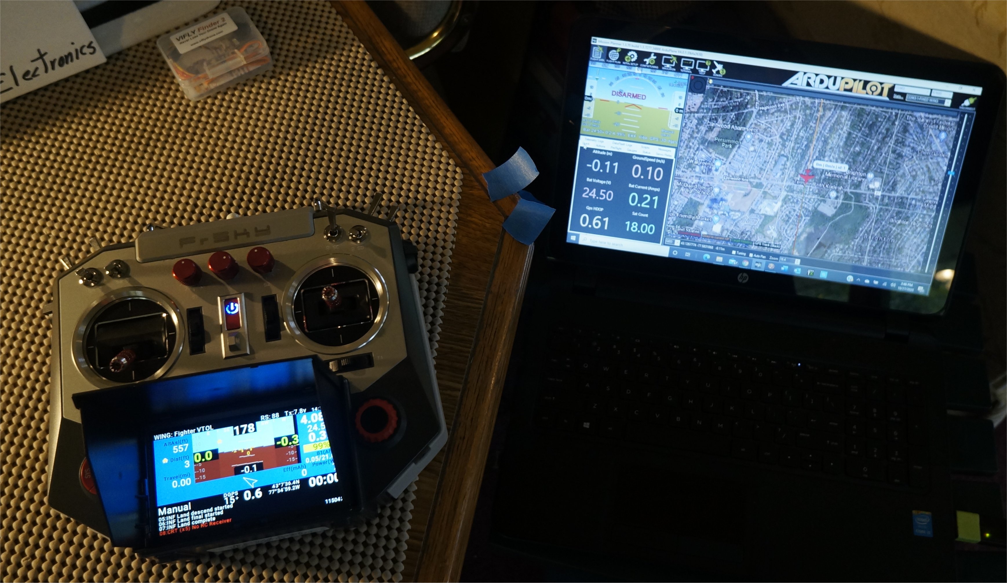
Now that I had servo power from my CC BEC, it was time to test my Mission Planner and Yaapu/FrSky telemetry setups on my Horus X10 along with proper tail operation. To my joy, it all worked great! To test the rudder, I needed to activate MANUAL mode from Mission Planner. I don’t have the Yaapu bi-directional features loaded yet so perhaps I’ll do it this winter. I make it a rule to never upgrade firmware during the summer flying season.
----------------------------- New Post --------------------------------
I finished my cable runs (or so I thought) so I screwed the middle guide piece in place. The wing locks were screwed into place on the fuselage as was the CG ring for testing later on. I didn’t understand in the video what the other two ring positions were for but they didn’t install them either.
At this point, I was done with the Assembly Guide 5 video less some wing wiring.
----------------------------- New Post --------------------------------
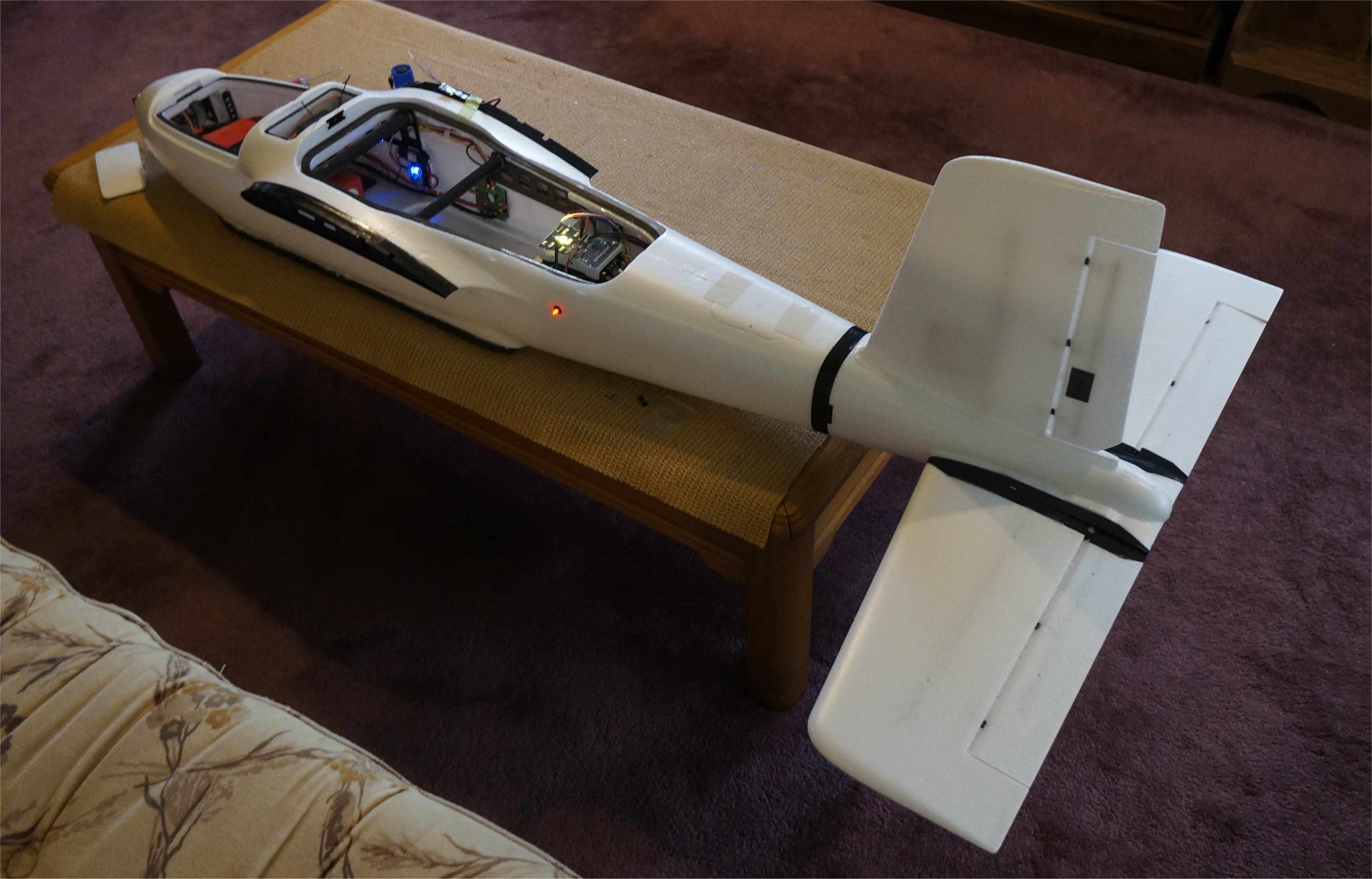
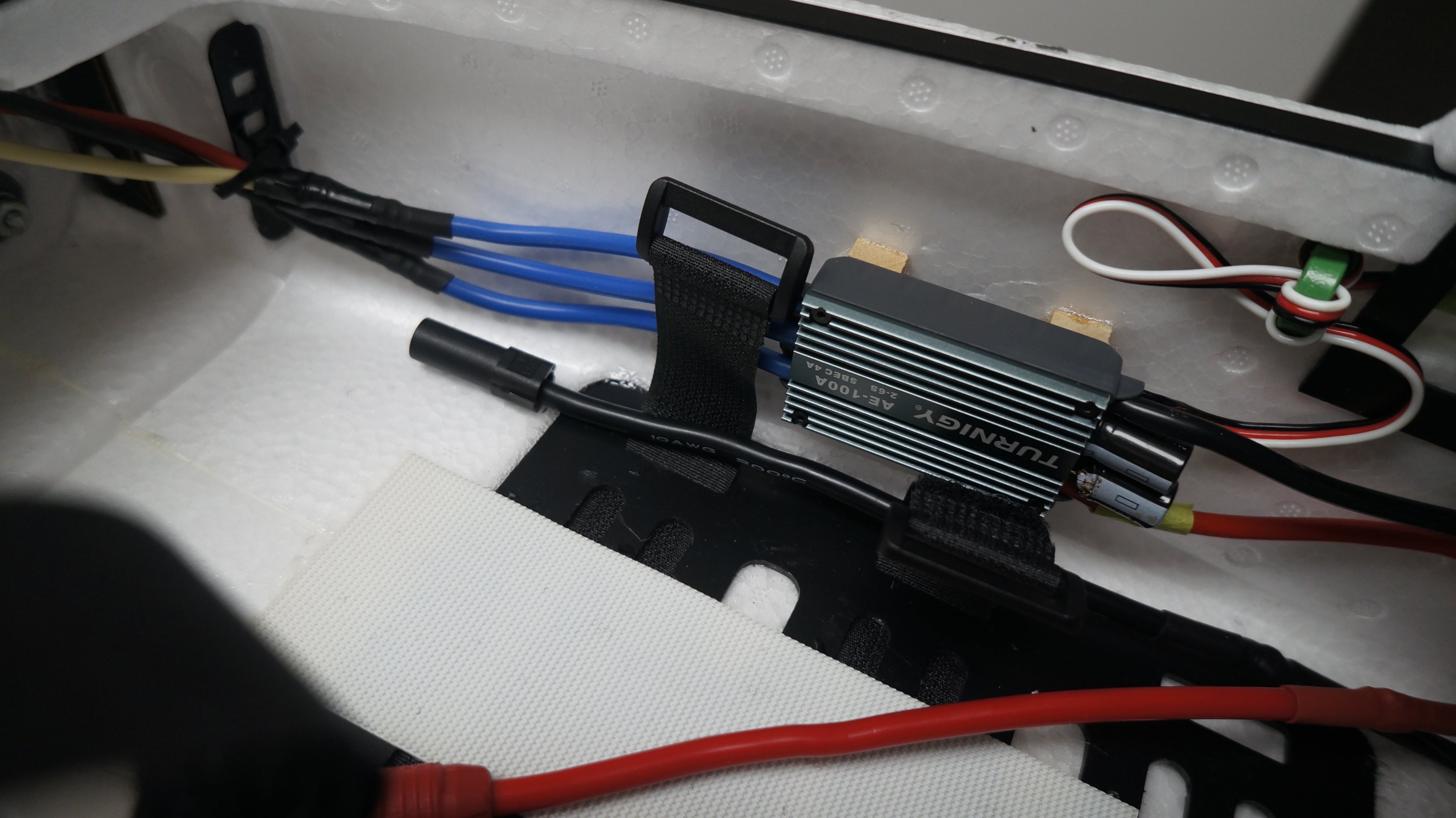
To finish up the initial fuselage assembly, I installed the forward flight motor and ESC. I didn’t care for the way the ESC was installed in video 6 (across the nose opening) so I mounted it in-line on the fuselage wall with two hardwood blocks. In this manner, air will flow across the heat sink area of the ESC. Further, without the plywood mount across the nose opening, the air flow will be less restricted into the fuselage body.
I wanted to keep a pair of bullet connectors open for the camera regulator power so I added another set of 3mm bullets to my distribution board for the FF ESC power. You can see the Dean’s connector and wires running in between the Mauch PM and 5v regulator. This was from a previous installation so I simply kept the wiring setup.
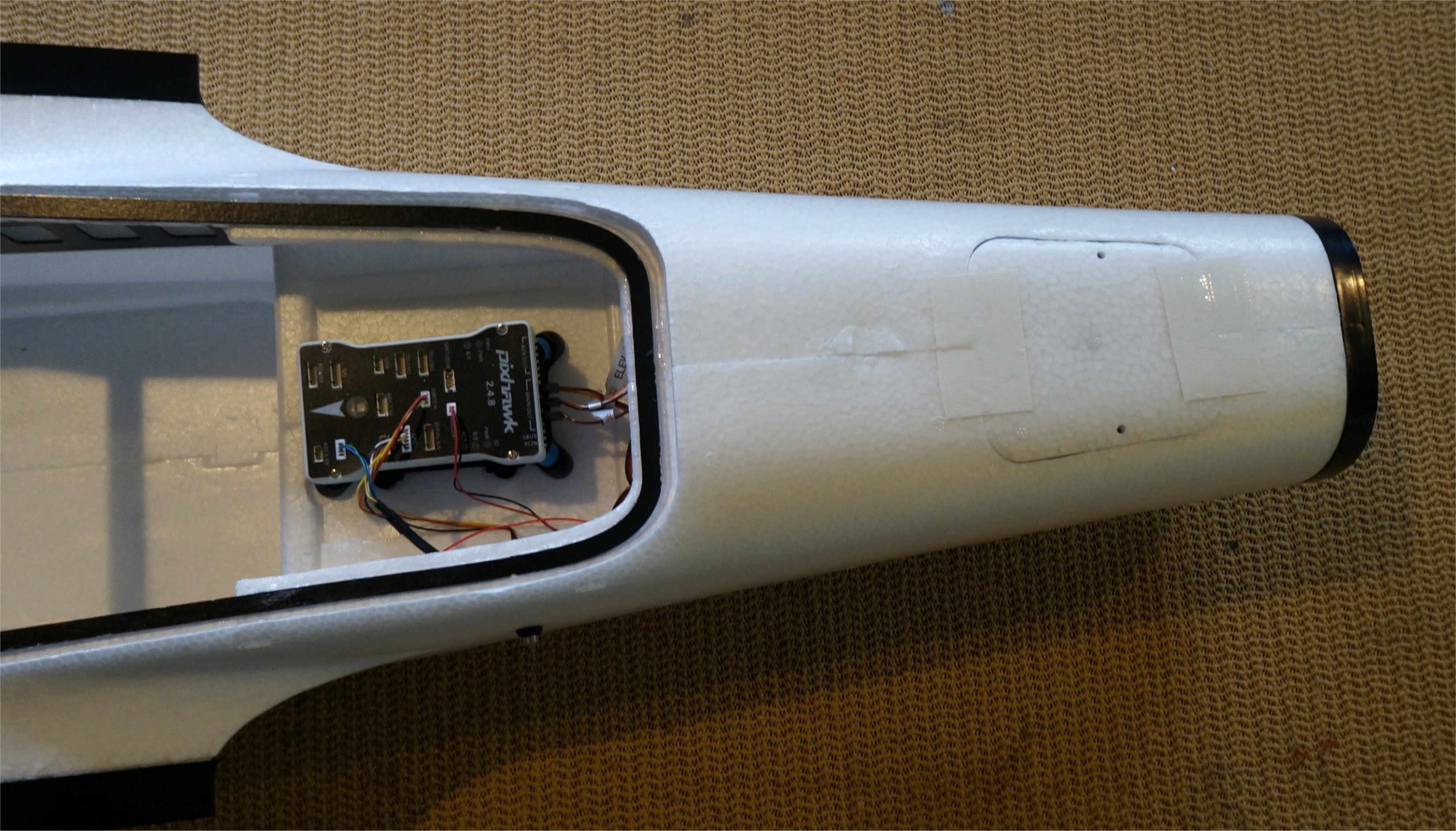
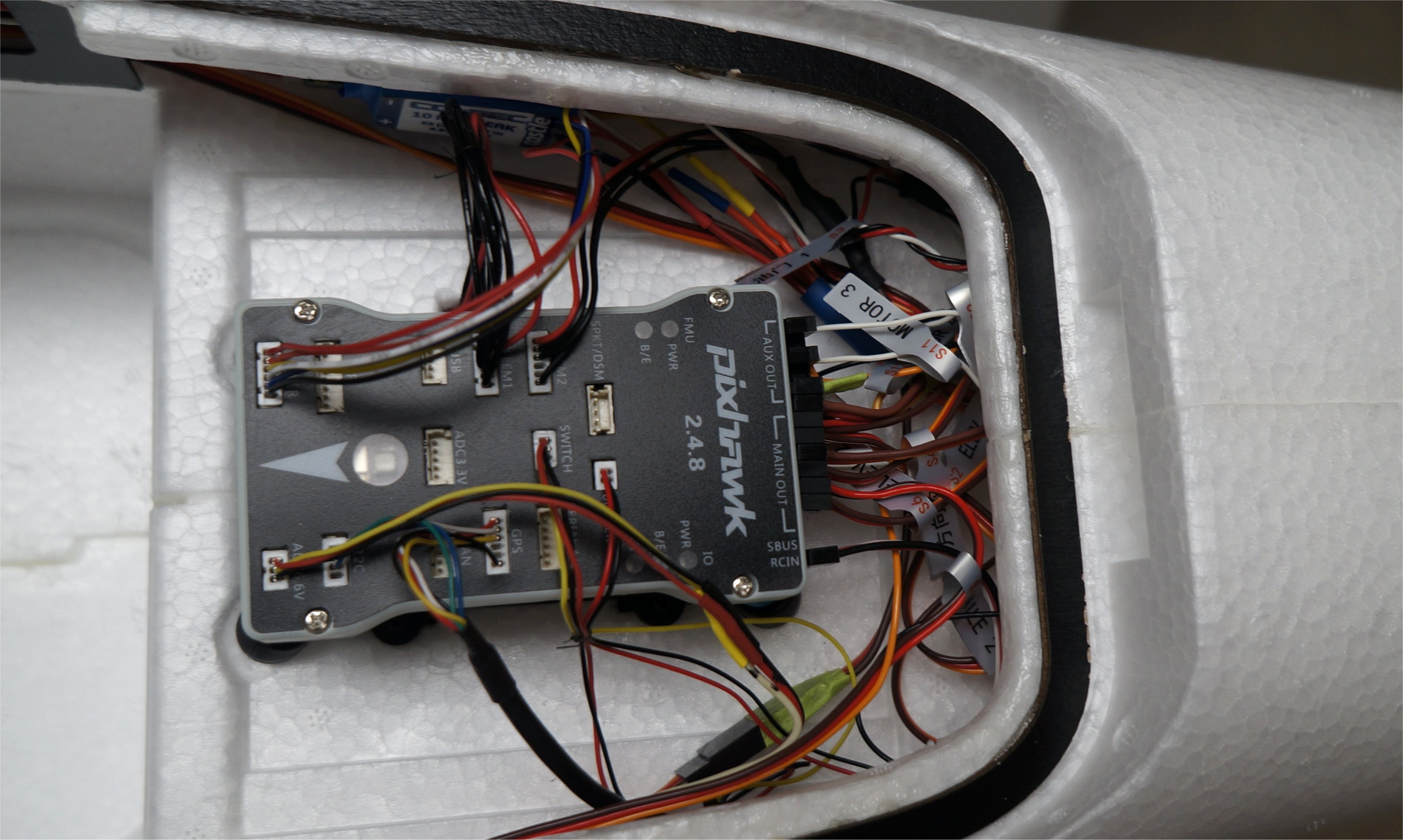
My Pixhawk v2.4.8 is now fully loaded. I decided to use an analog AS sensor since I had several on hand instead of buying a new I2C sensor. By keeping the servo wires relatively loose, it provides better vibration isolation than using cable ties to make it look neat. All the cables are labeled with the supplied stickers.
1 Like
Greg,
where did you end up mounting the Airspeed sensor?
I noticed the MFE PNP has it in the wing with a long tube so that it can reach beyond the wing front edge. The consumer airspeed sensors are much shorter. I might recess it into the wing, though I’m still waiting on parts to arrive before I start modifying the foam.
Christian
Christian,
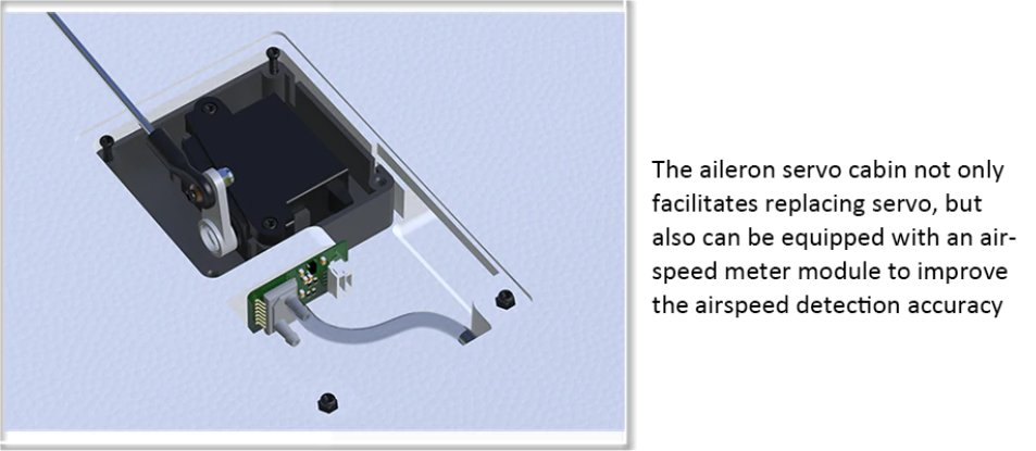
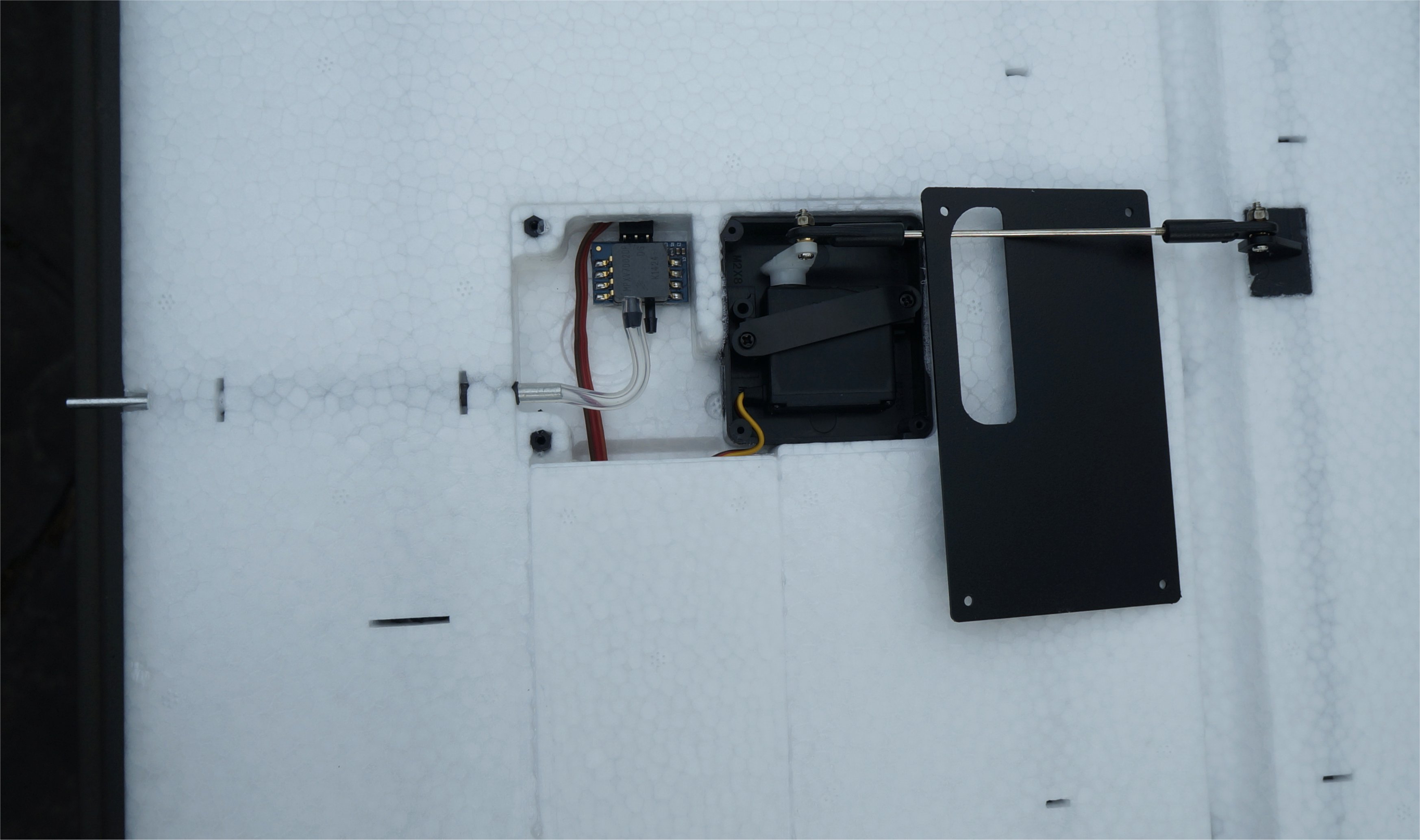
I haven’t mounted it yet but my intention is to mount it in the left wing as shown in the image below. I have wired Connector 2 on the left side that goes to the 3-pin Molex for analog AS sensor on a Pixhawk 1. The rest of it is standard 3-wire servo cable to the sensor and then a few inches of air tubing.
It looks like either wing has a tube already built into the aileron servo bay leading edge. It looks like you put your own copper or brass tube inside it and simply connect the hose to it and open up the leading edge hole. I haven’t fully investigated it yet. I like the idea that the static air pressure is sensed inside the chamber and only a small portion of the active tube protrudes from the leading edge.
Conn 2 (Left)
- 1 Gnd (Black)
- 2 +5v (Red)
- 3 Analog AS Sensor (White)
- 4
- 5
- 6
- 7
- 8
- 9
1 Like
Greg,
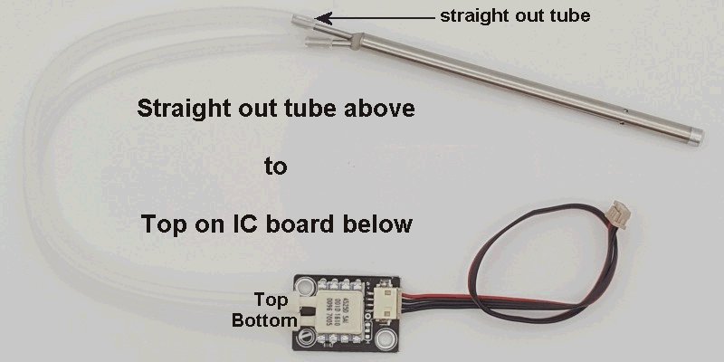
This a spare Holybro digital airspeed sensor I have which worked quite well on my last build. As you can see, it’s not long enough to use inside the servo compartment.
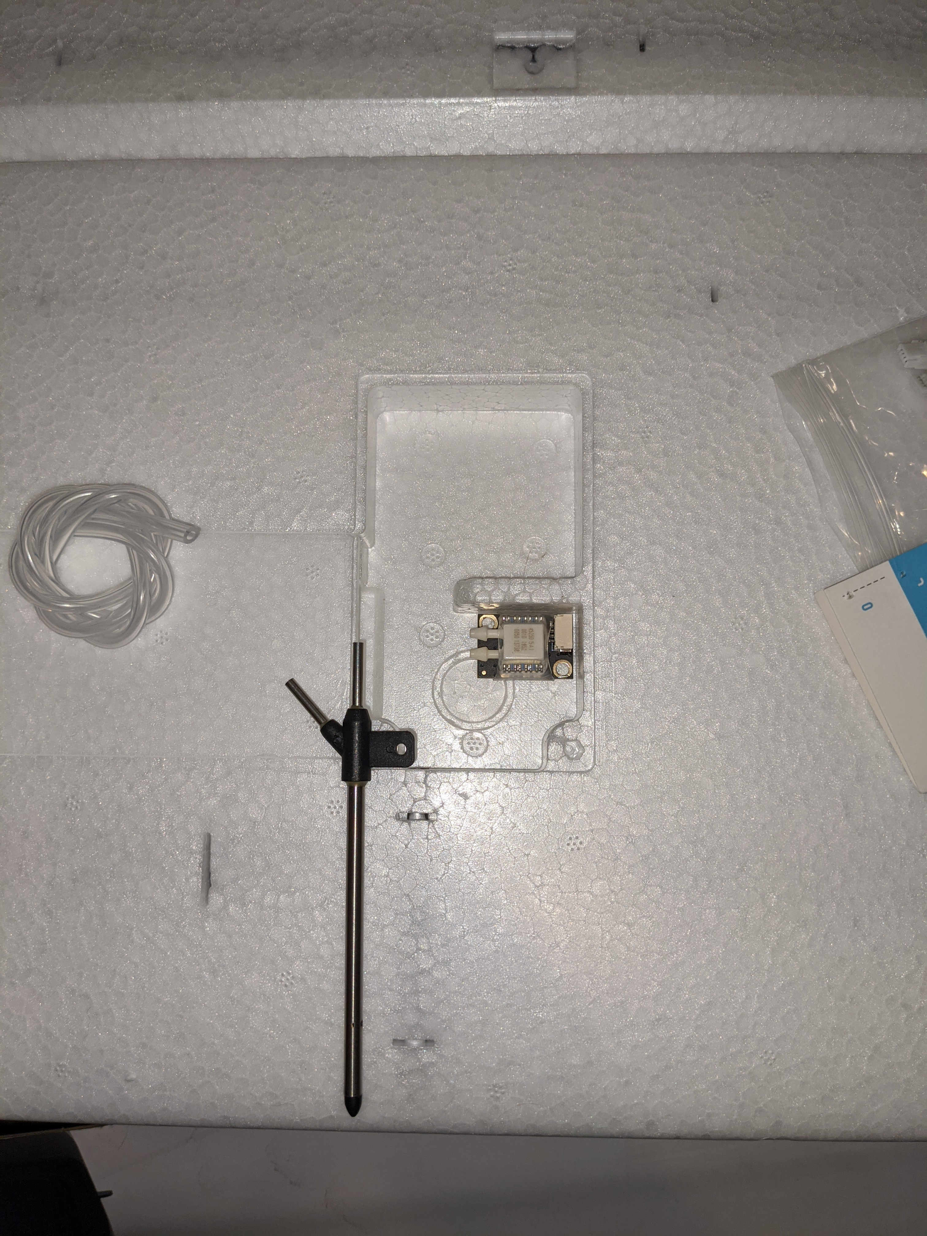
I didn’t notice the routing tube when I was first checking kit parts. It is too small for the airspeed sensor I have on hand even if it were long enough to clear the wing edge. Looks like I’ll be sourcing a sensor that will easily fit in that space.
Christian,
The wing is foam so put a new blade on your Exacto knife and have at it. I love cutting foam to suit my needs. First, cut out the existing tube and then cut an area to fit the black base of your pitot tube. No need to spend money when you can have fun bashing!
Alternatively, it looks like a 2mm (0.0787") or even a 3/32" (0.0938") tube fits nicely inside the built-in tube. I tested both the 2mm tube and 3/32" tubes. Both have a small amount of wobble space. The scrap piece of plastic tubing I had lying around fit snuggly over the 2mm tube so I will likely use this combination and follow the video installation. The static air pressure intake then has no connection as it is inside a loosely sealed plastic box. A nice design feature on the Fighter.
Good luck!
----------------------------- New Post --------------------------------
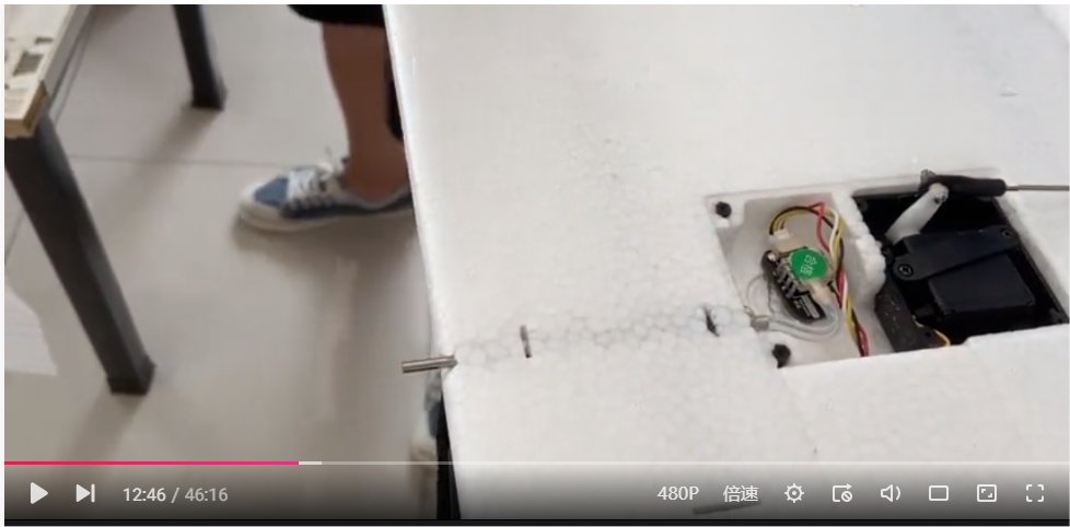
Since we were on the subject of AS Sensor, I decided to install mine. It turns out that I do have a spare I2C AS Sensor so if my Analog sensor gives me an issue (due to the cable length) I can swap it out. There are so many spare pins on Connector 2 that I’ll wire up both the analog and I2C lines for the left wing.
I cut my 2mm tube to 100mm length and pushed it into the wing tube from the front. To make a nicer 90 degree bend in the fuel tubing, I cut an area open for the servo connector to go in. The installation was clean and simple.
1 Like
Okay, gotcha.
I didn’t realize this was a partial mod by leaving the static pressure tube off. I’ll probably do the same mod to keep things cleaner on the install and for simplicity sake if there are no adverse effects.
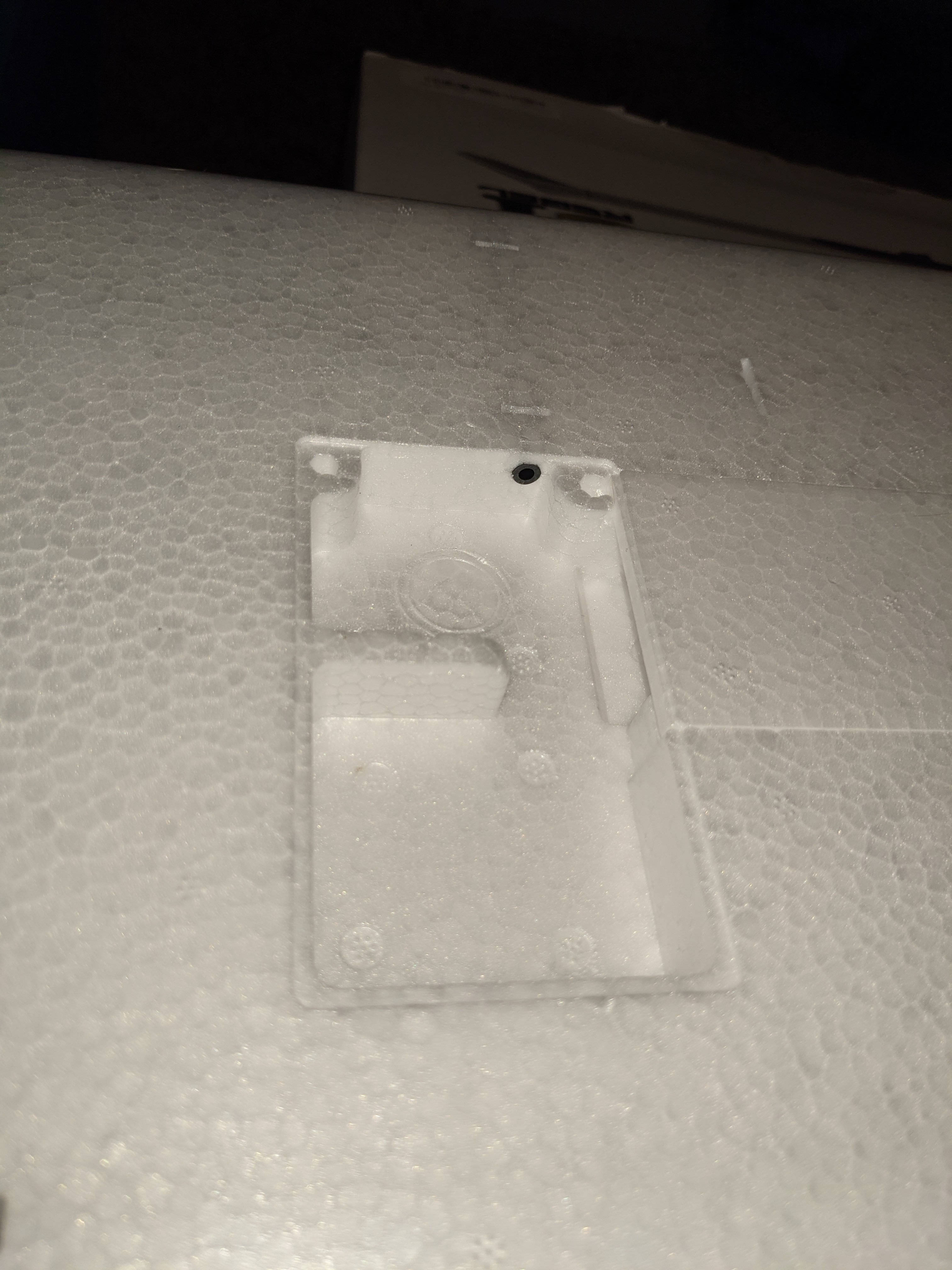
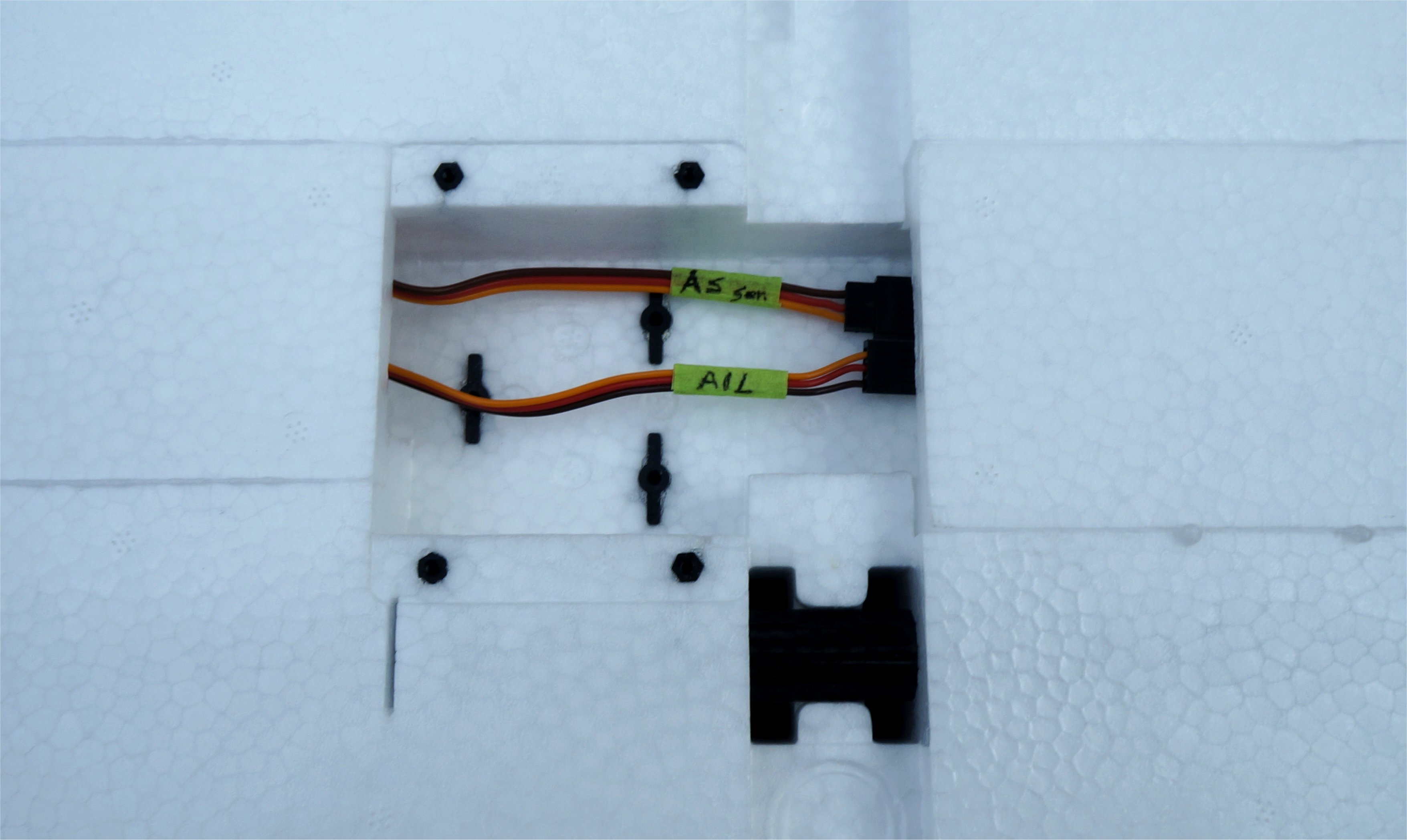
Space was tight for the AS connector so I am planning to cut a recess in the foam and add a single loop in the tubing as I did on a previous build (see below).
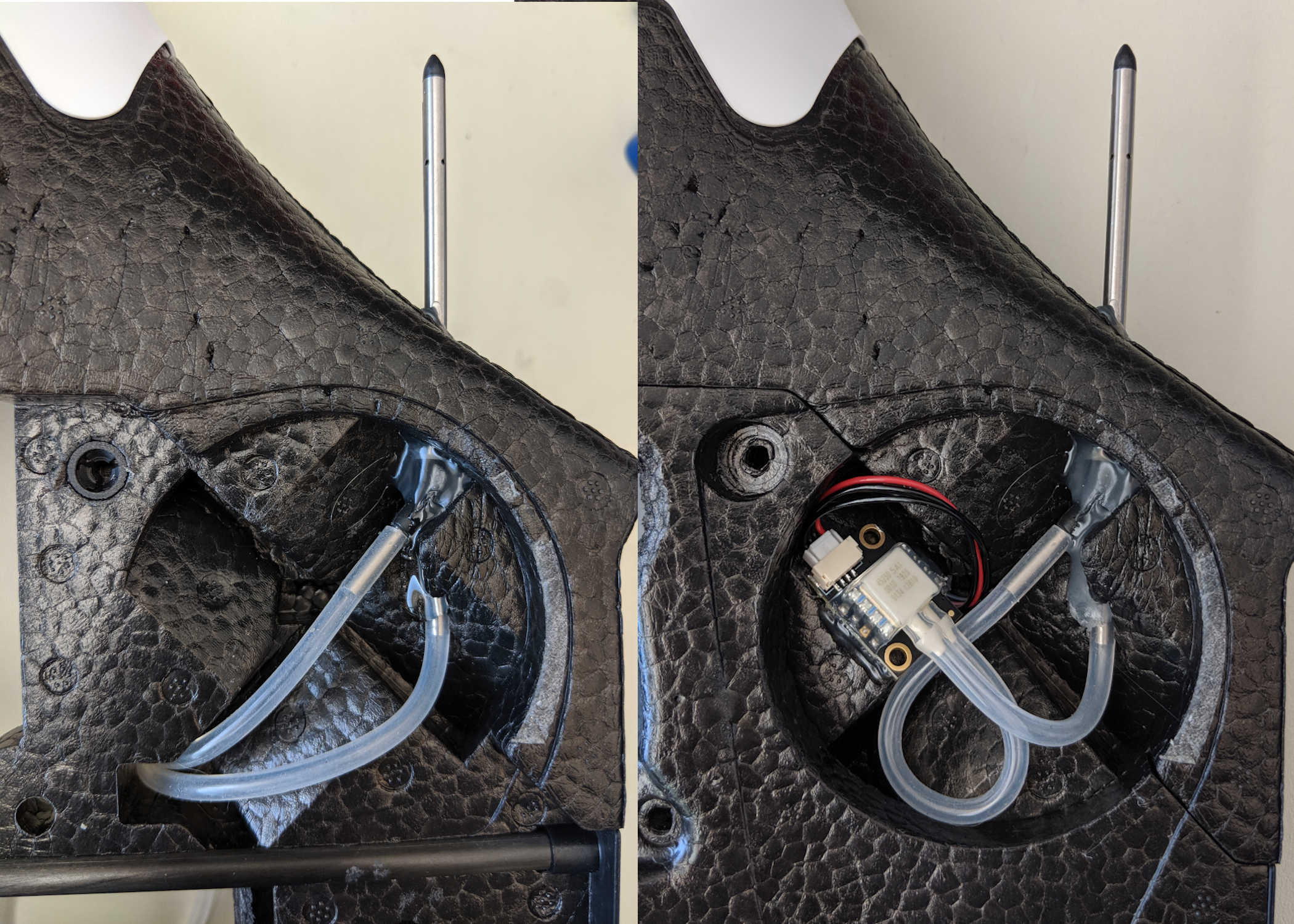
BTW- I love hacking foam, but avoid it if/when possible.