Thanks Greg,
I just plugged in your Fighter PNG to my Horus model screen - looks great…thanks.
Cheers
Jeff
Thanks Greg,
I just plugged in your Fighter PNG to my Horus model screen - looks great…thanks.
Cheers
Jeff
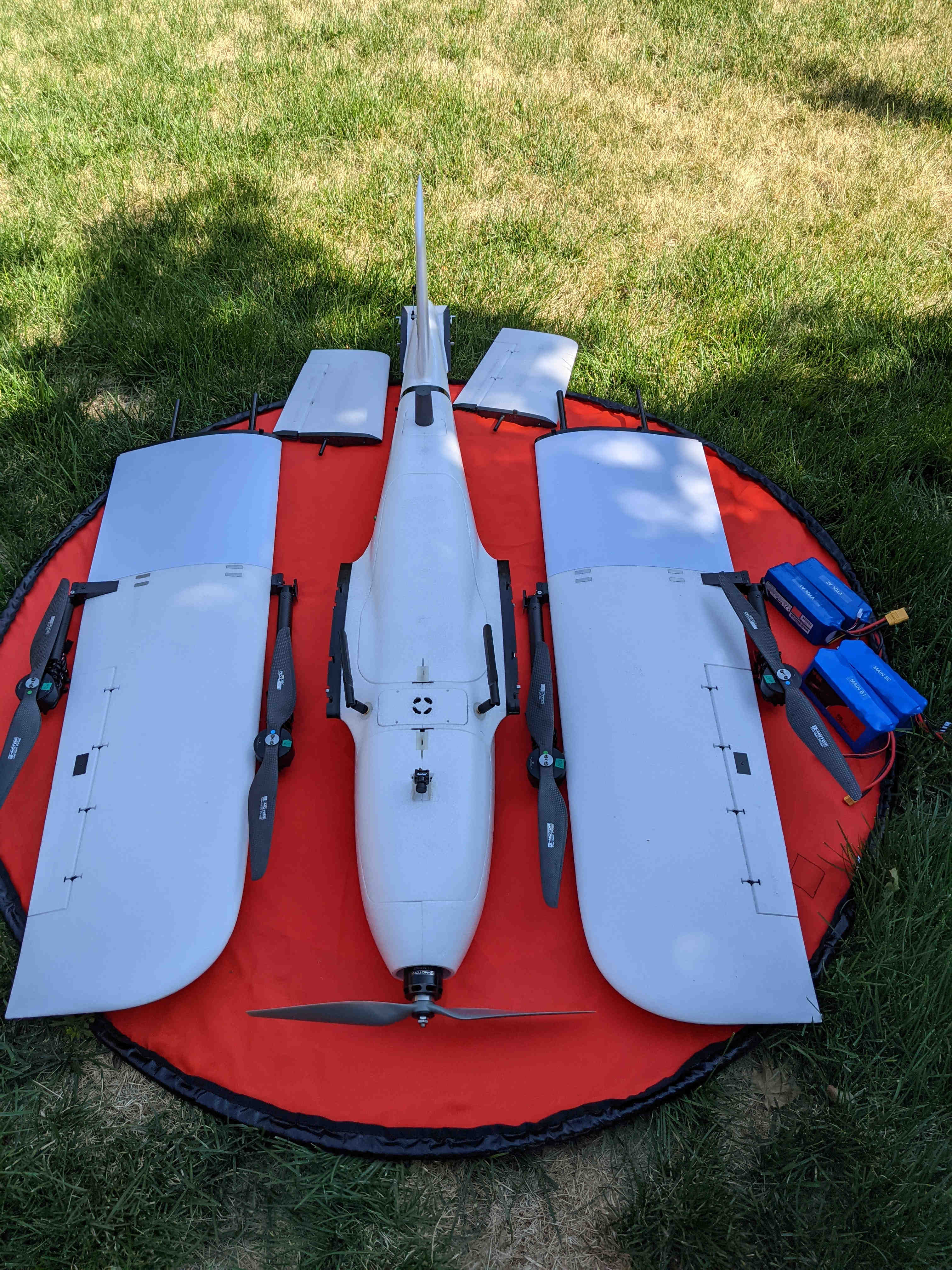
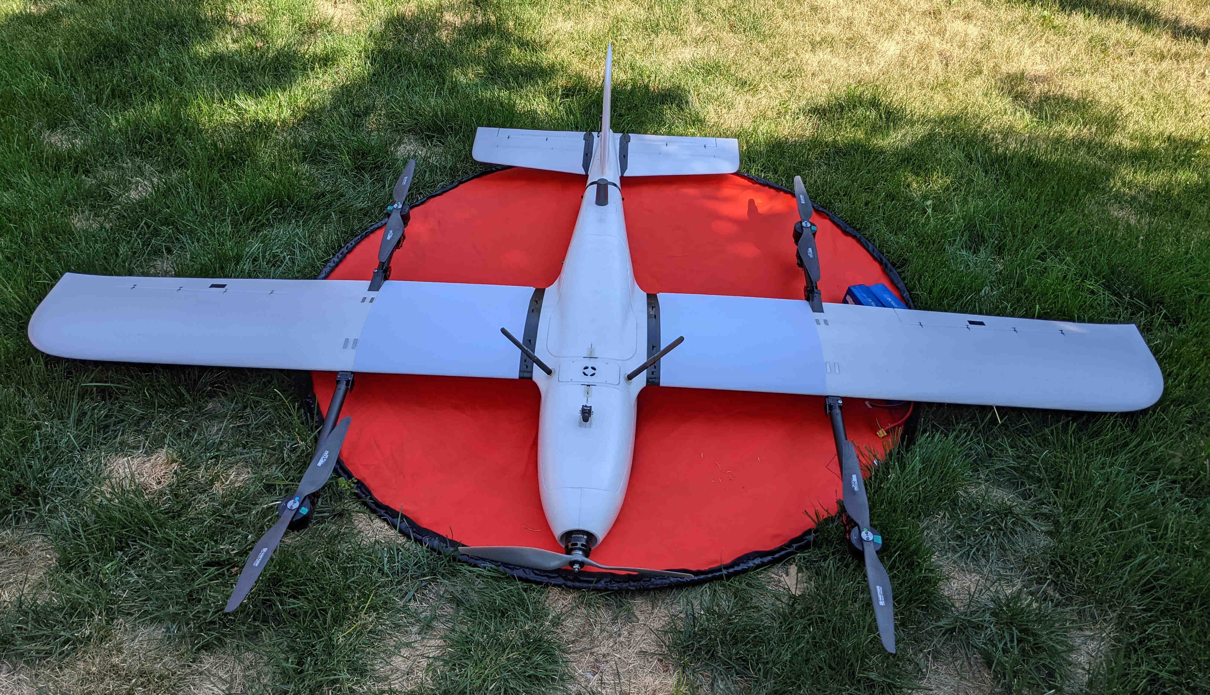
Since I’m grounded for a bit due to software issues, I decided to take a few new photos of my VTOL build to share with others. I’ll add brief details among the photos for some aspects of the build that may have deviated from my initial plans.
Approximate weights (± 30 g using a hanging fishing scale) are as follows:
Dry 6.53 kg
Wet 10.33 kg (without multispectral camera)
MTOW 10.78 kg
I decided to nix the idea of using a PDB in the wings and just solder the power connections for the VTOL motors so I could save some weight.
The Mauch Power Cube has the option to use an external switch to control power to the board. This made things very convenient as I was testing different connections since I didn’t have to plug/unplug the Primary batteries each time I cycled power. The LED will be solid when the board is powered and blink intermittently when powered off but still has the batteries connected. I highly recommend considering the power switch if you use a Mauch Power Cube.
The soldering and routing of wires for the VTOL motors and ESC’s were a little tricky to sort out at first. After I had decided how I’d approach the problem everything went fine. On the first motor I soldered bullet connectors so that I could test spin direction on the bench. Afterwards, I resoldered the wires directly for the first and each subsequent CW and CCW motor accordingly. I had to cut out a little bit of foam in the Fighter shipping box so that there was space for the externally mounted ESC’s. I still stand by my earlier recommendation of going with the TMotor integrated arms to save you time and hassle during the assembly phase.
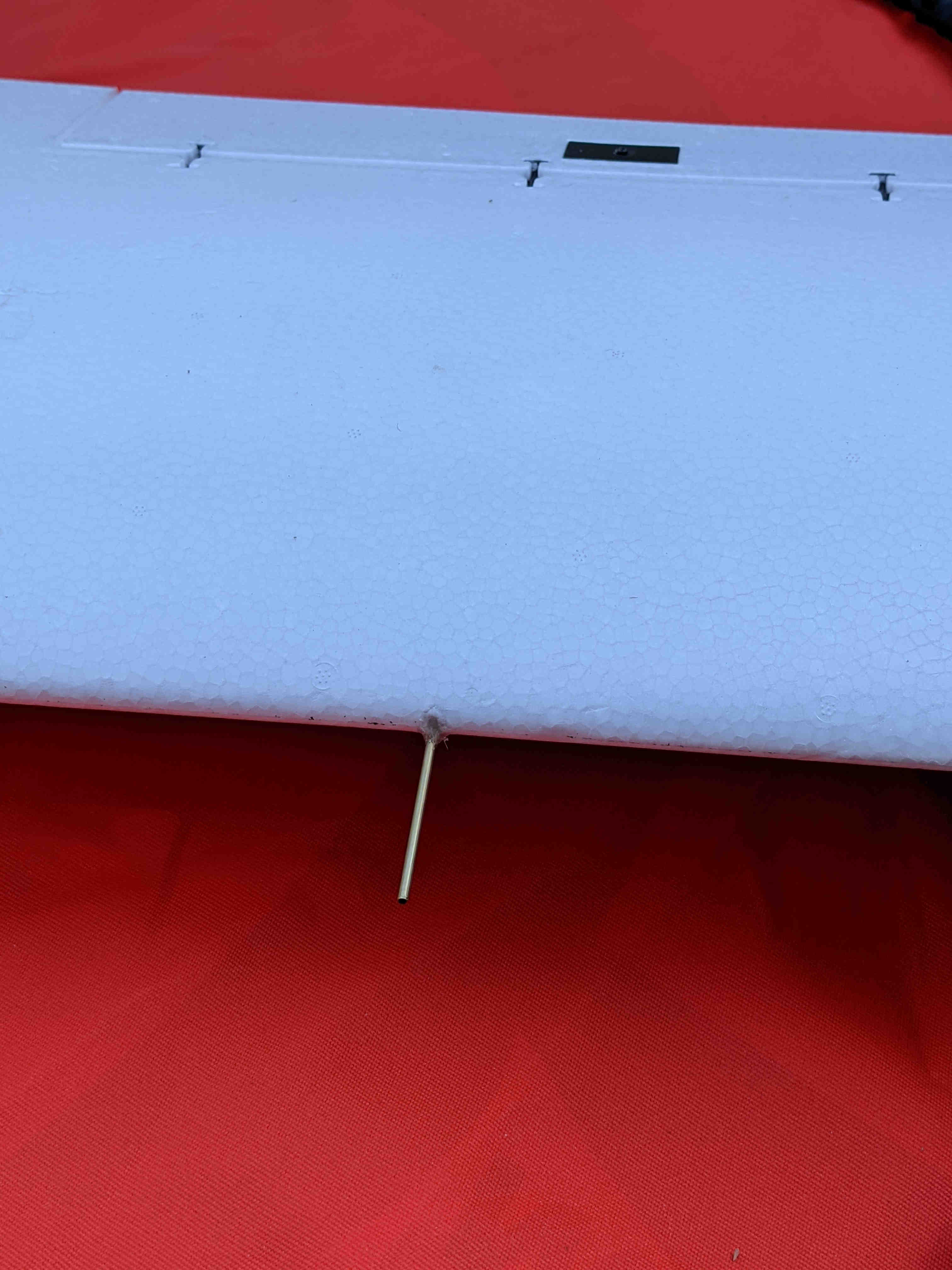
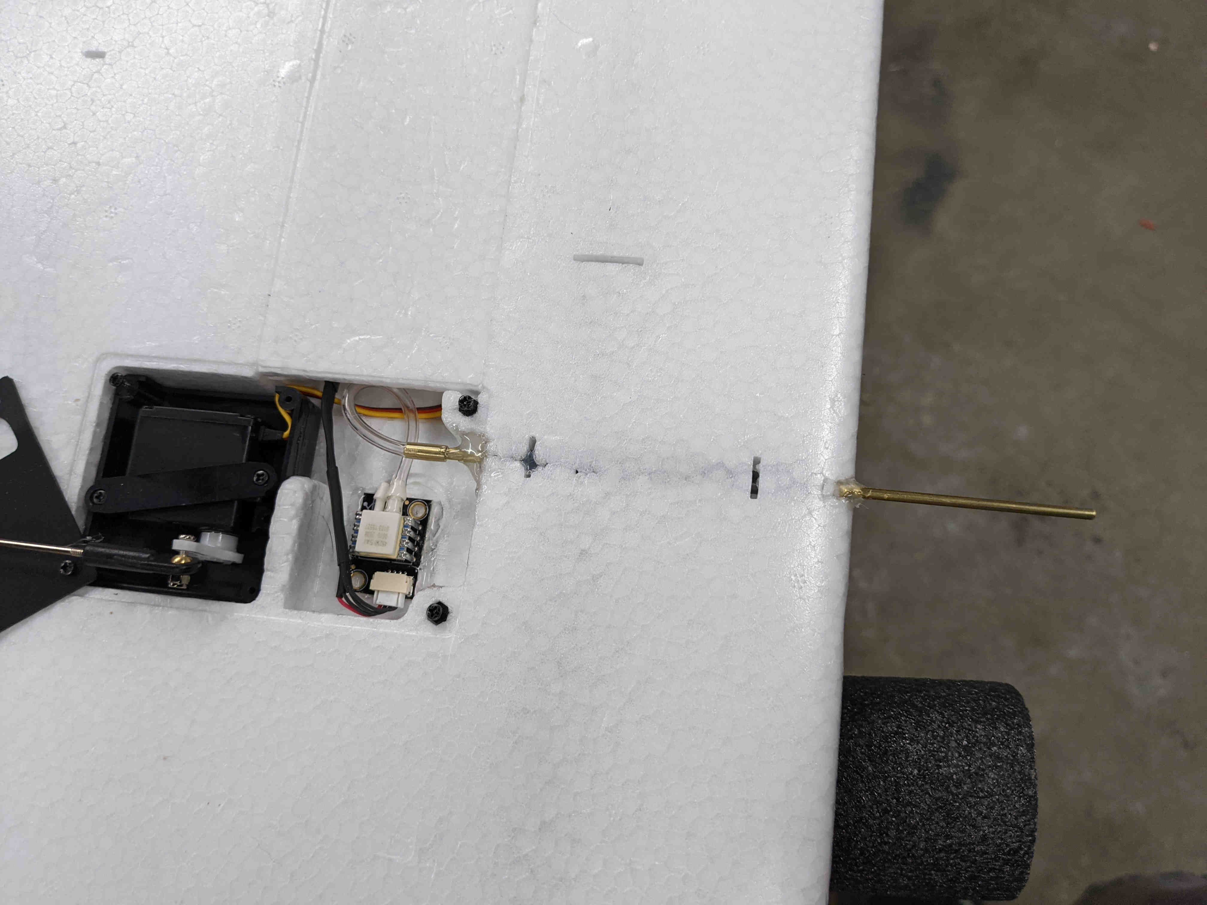
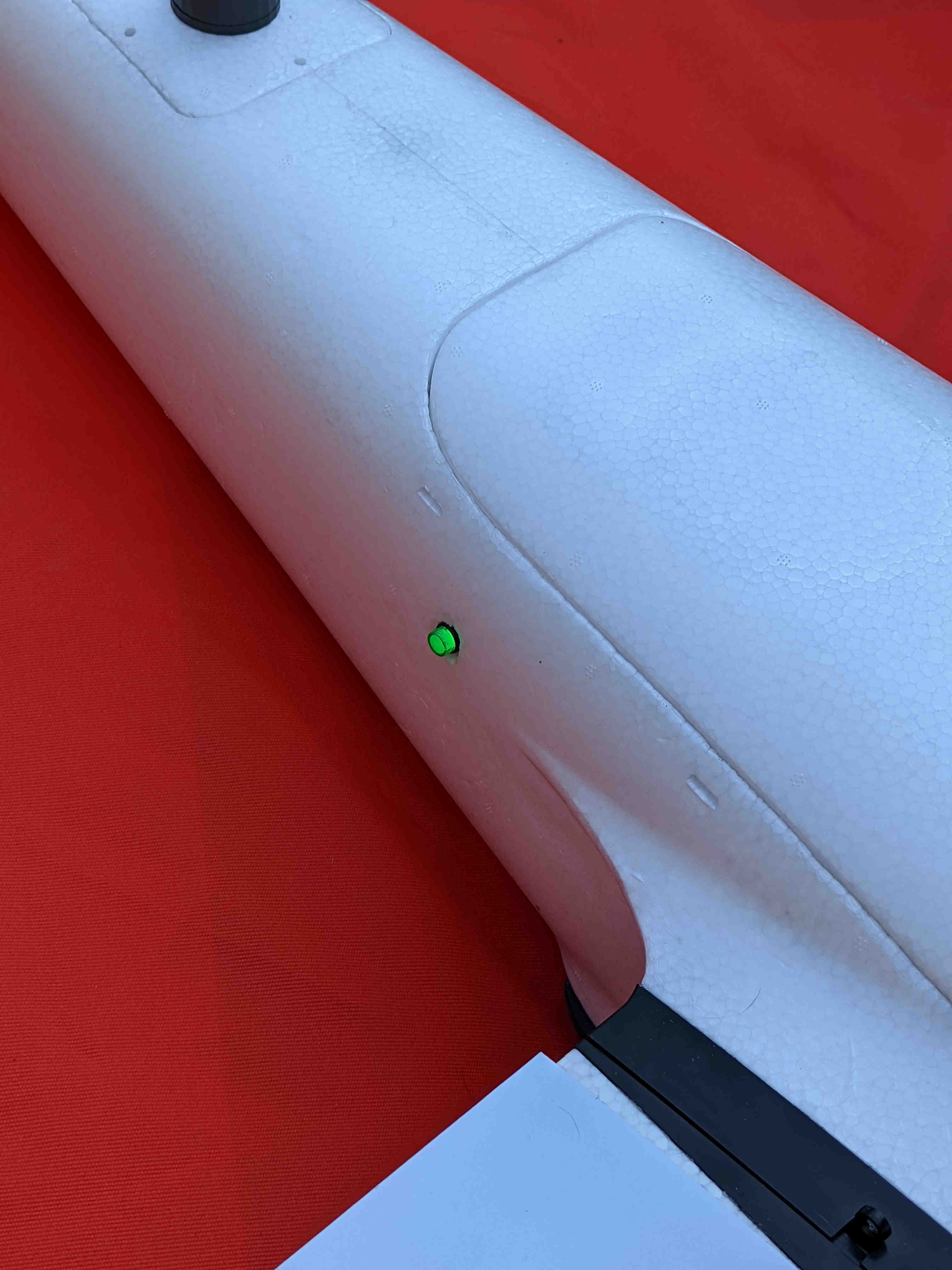
The RC antennas used are made by Airbot and meant for the Herelink system. Their advantage over the stock Herelink antennas is that these are easily removable. They are mounted nearly perpendicular w.r.t. each other for signal coverage because they are omni-directional antennas. I went back and forth on whether to mount the FPV camera now or wait until later since it wasn’t an immediate necessity. I went for it and I decided to make a polycarbonate mount for the camera which was very simple to implement (vs. firing up the 3D printer). I used cold breaking/forming (bending) techniques and only had to attempt it once to get the right fit. This mount allows for adjustment to the camera pitch. Later I would like to remount with a servo so I can pan inflight…
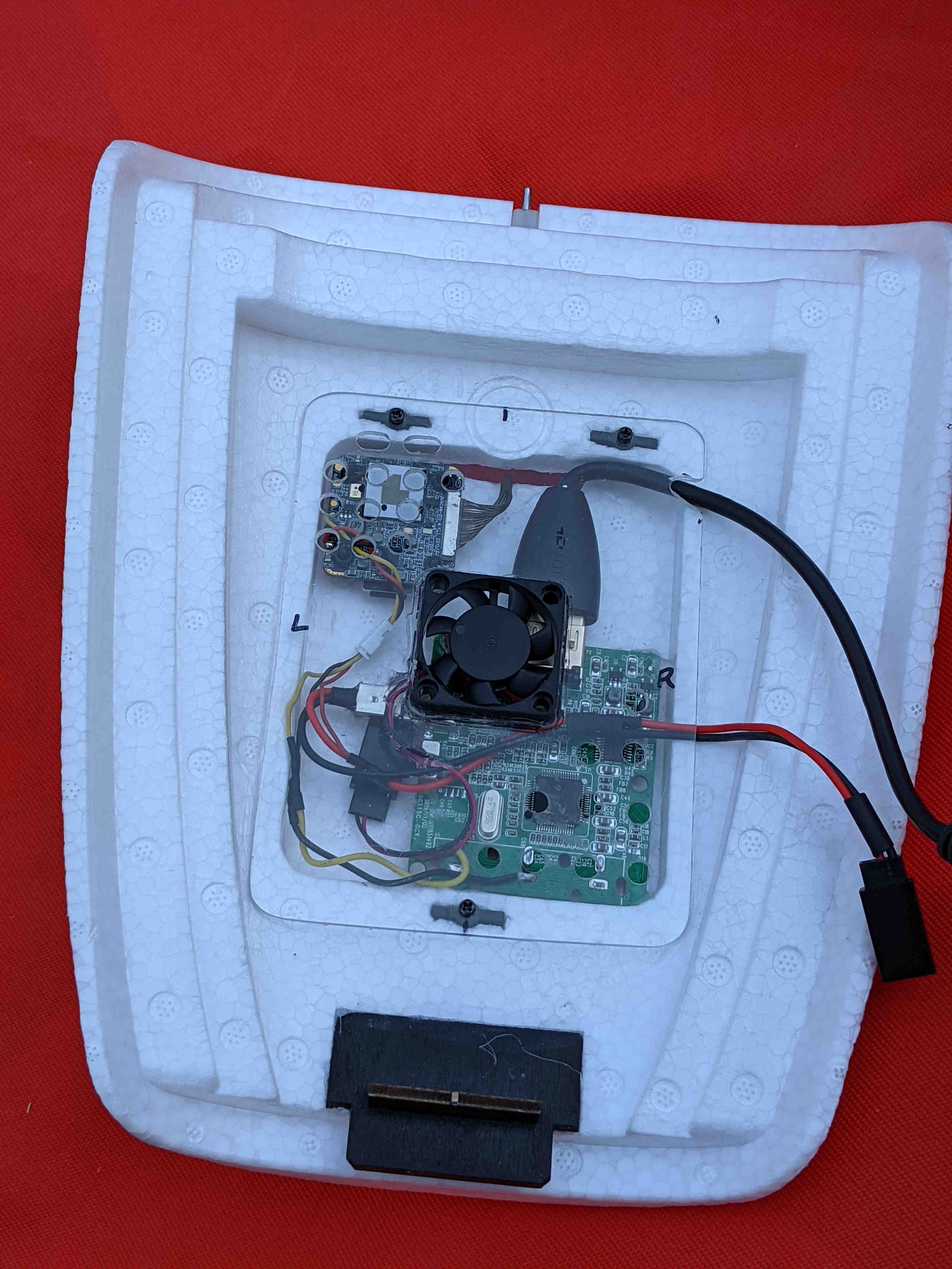
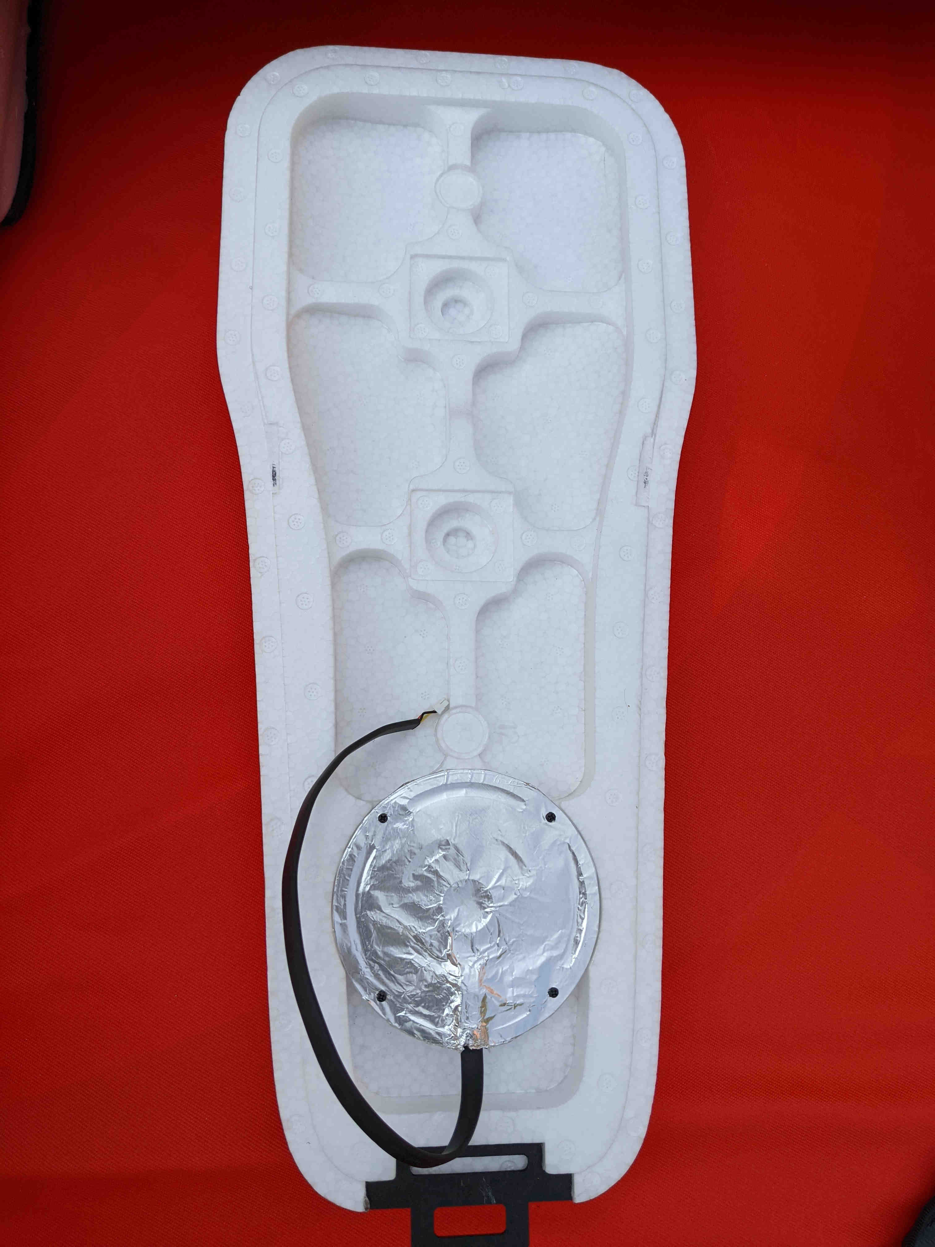
The FPV system consists of the camera board and the analog-to-digital video converter. The converter is quite bulky in its case and after removing the plug connectors to save weight (thanks for the tip @GregCovey) the board is still wide but pretty thin. Everything fits nicely inside the recess in the front hatch cover. The camera board and converter get hot without air flow so I added a polycarbonate cover for protection and a 5V muffin fan. The fan pushes cabin air toward the hot boards and exhausts either through the holes in the polycarbonate or outside the airframe through the hatch penetration. This has worked great managing heat thus far with the Fighter sitting on the ground, hatches closed. I used some of the leftover MFE plastic anchor inserts to attach the cover.
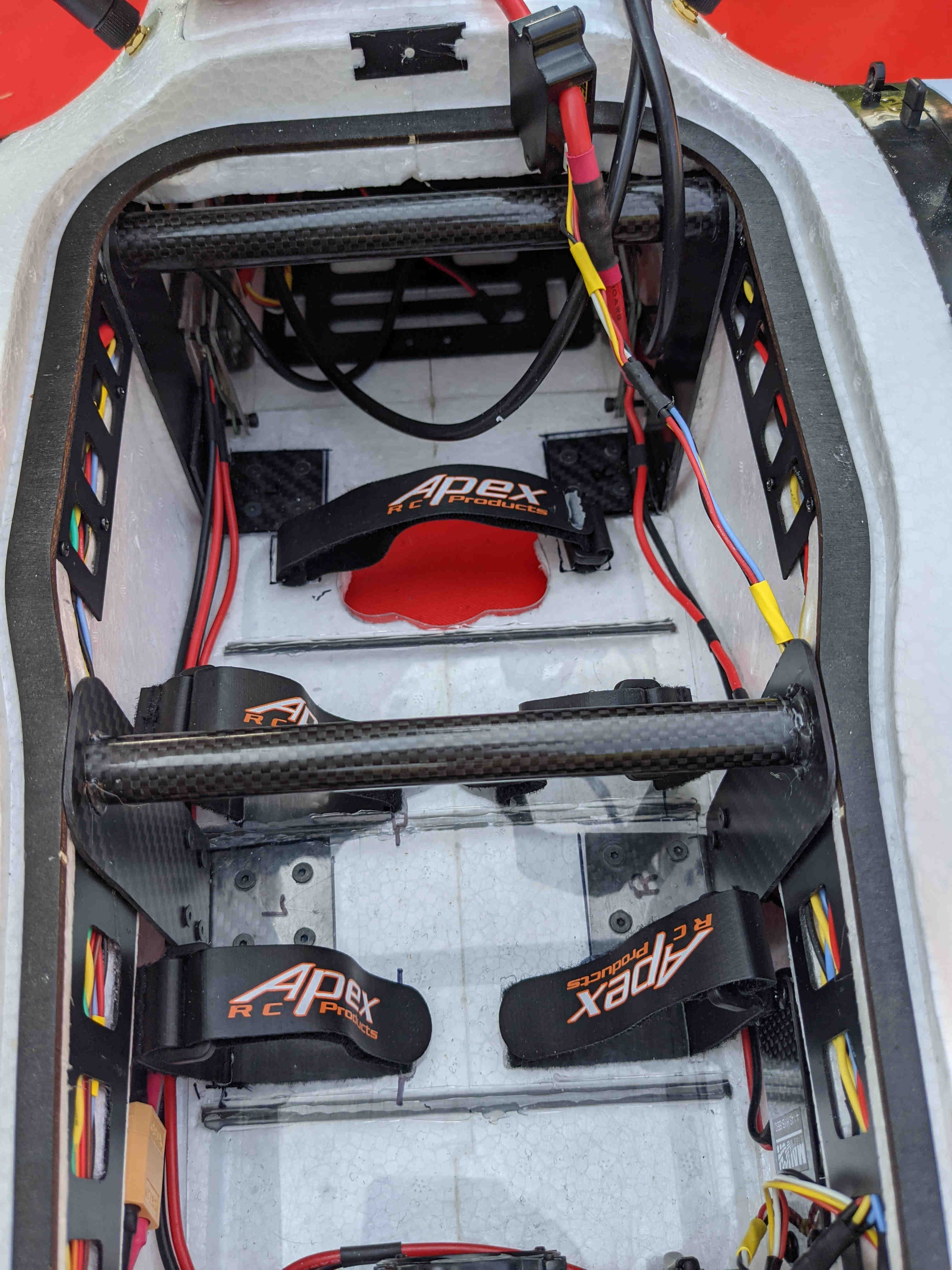
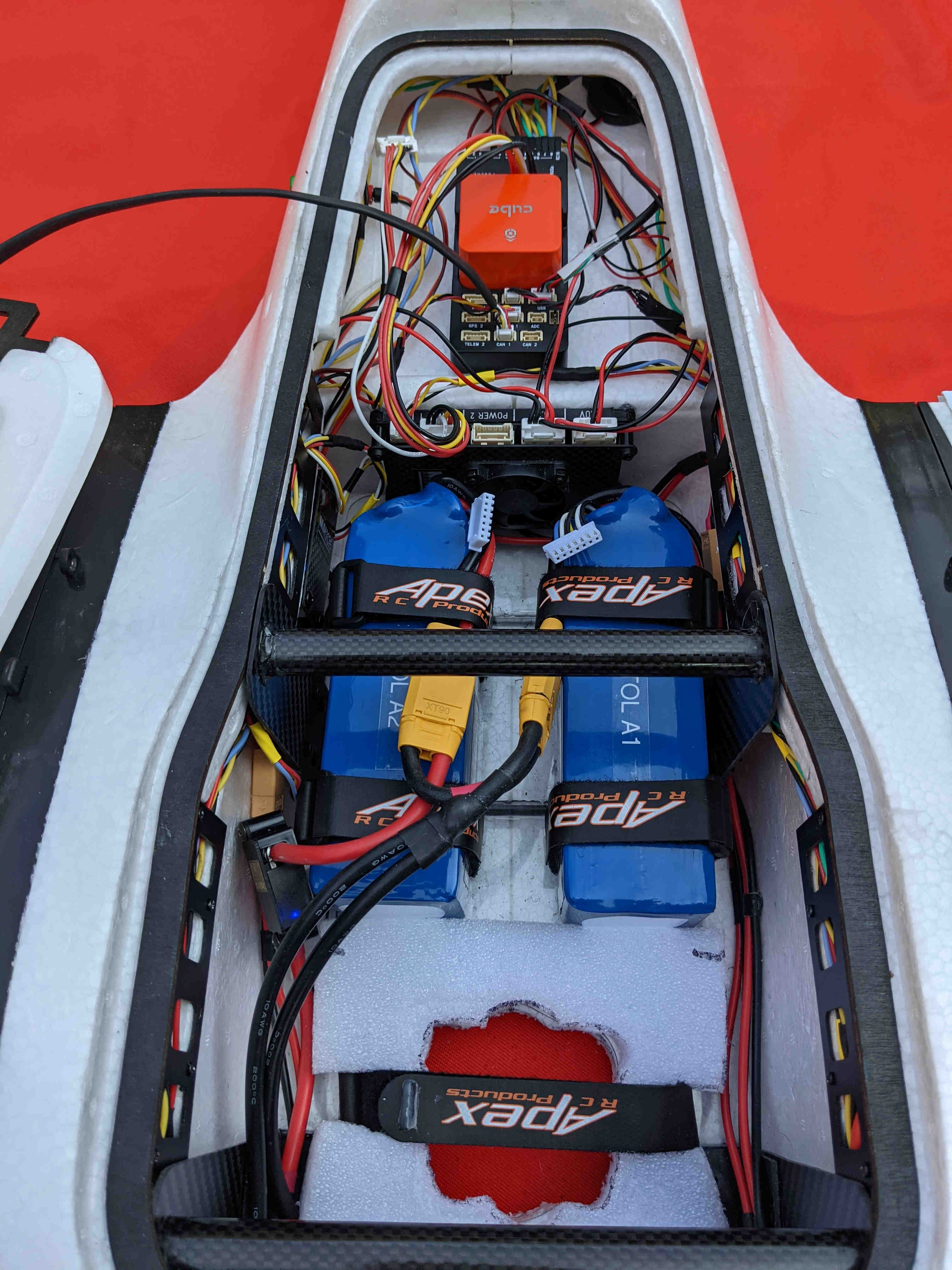
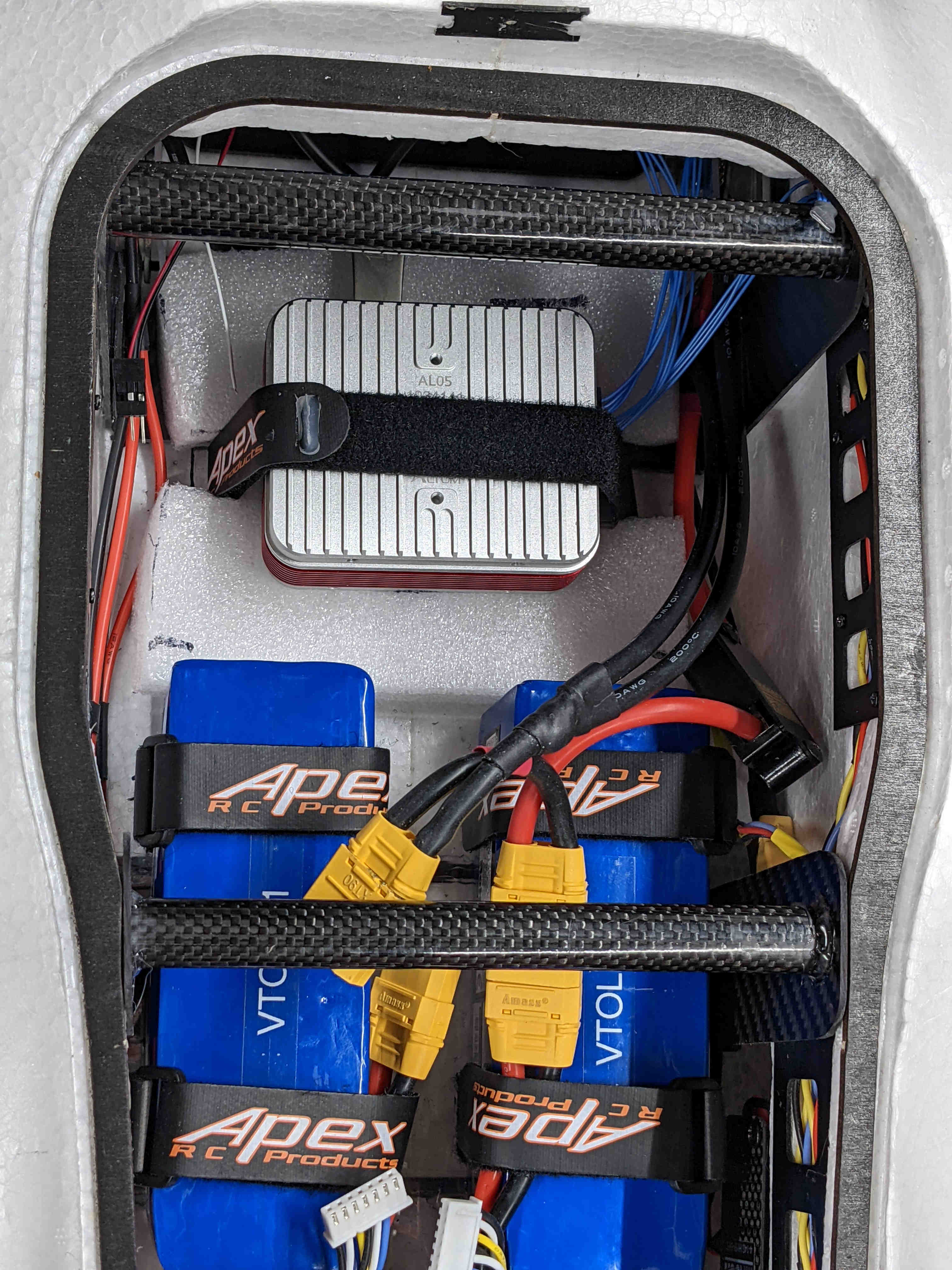
Each power circuit (Primary, VTOL) uses a PDB as the main junction. I didn’t have the right epoxy/resin to “pot” the exposed contacts so I opted to sandwich the PDB’s between two pieces of polycarbonate. This provides protection, an attachment surface, creates an air gap between the foam frame and the exposed solder joints, and allows access to the PDB’s for future power modifications.
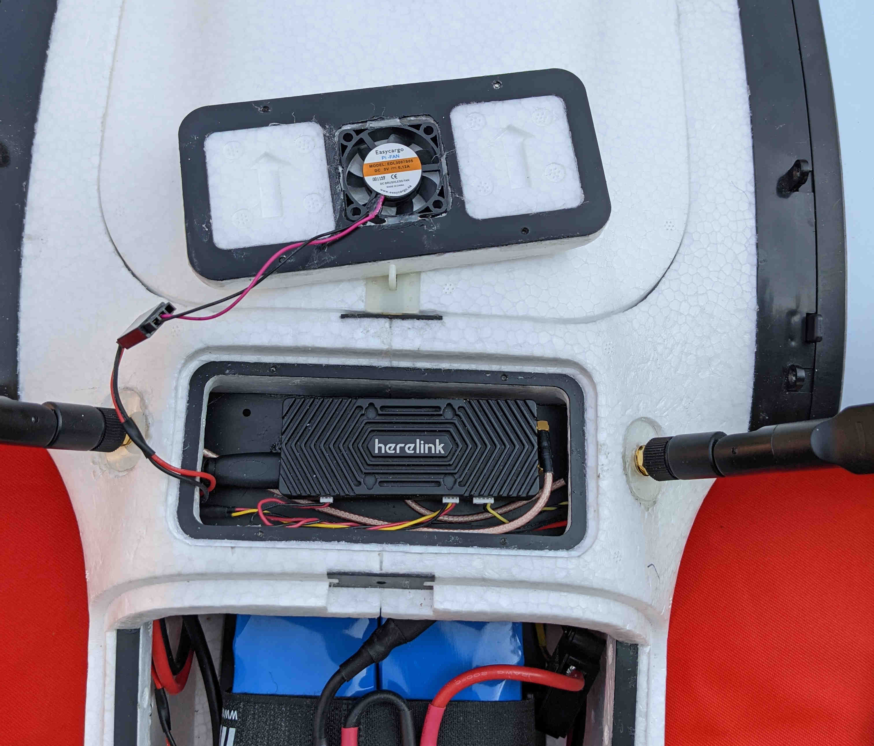
The Herelink Air unit gets hot without active air flow, even in open spaces.The unit fits well inside the RC hatch, however, it requires airflow so a 5V muffin fan was recessed into the hatch to be minimally invasive inside the compartment. The fan pulls in outside air for cooling.
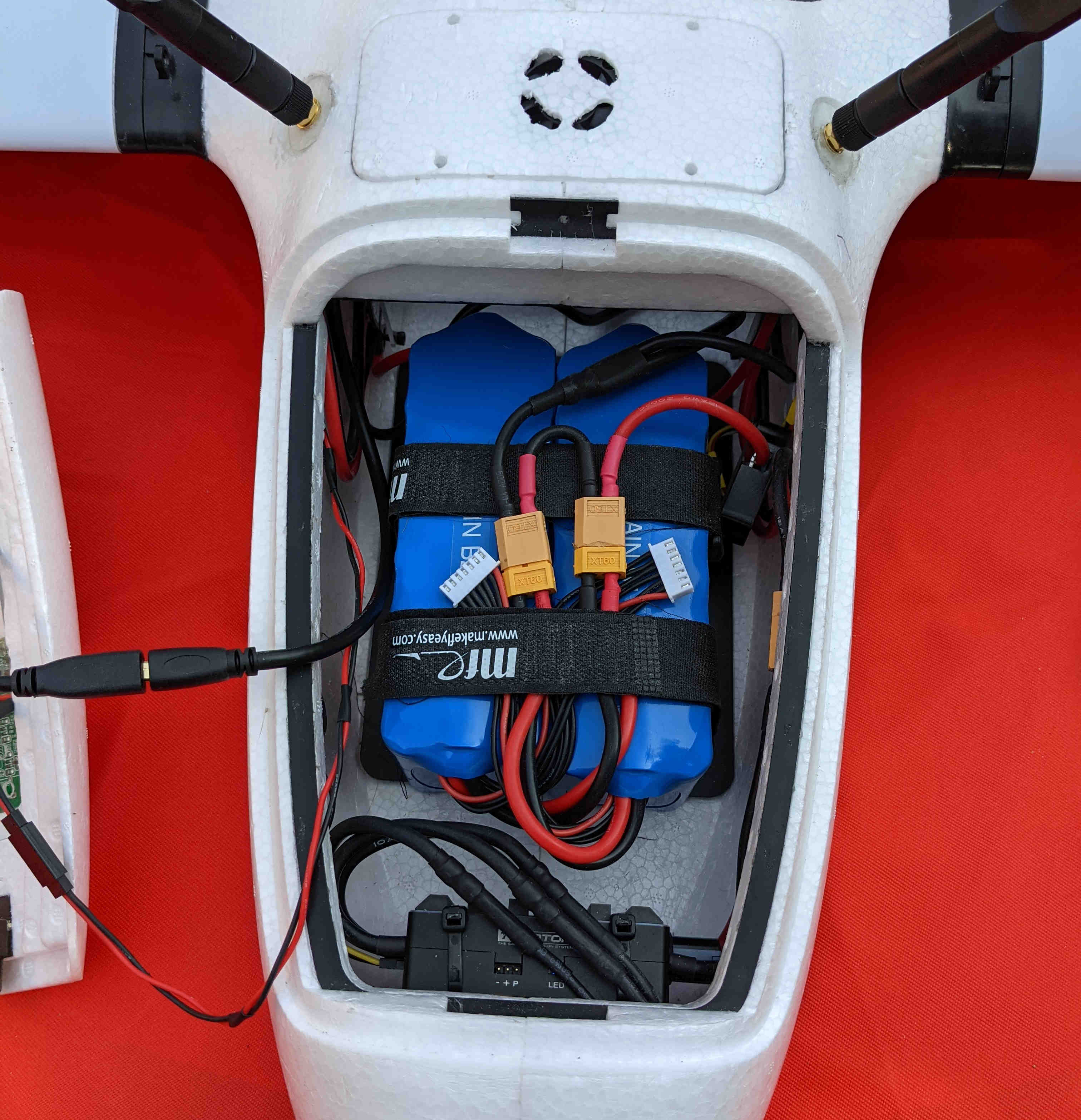
To support the weight of the VTOL system batteries I made a polycarbonate battery tray reinforced with carbon fiber spars laterally and then carbon fiber uprights. This helps to transfer the load to the central wing spars so the extra weight is not being held solely by the foam sides and bottom of the fuselage. The battery tray is removable as well as the rear carbon fiber uprights (note: rearward central wing spar is removable via a clever MFE design). Because the battery tray is removable it allows for a slung payload sensor (or another payload arrangement) in my next building phase.
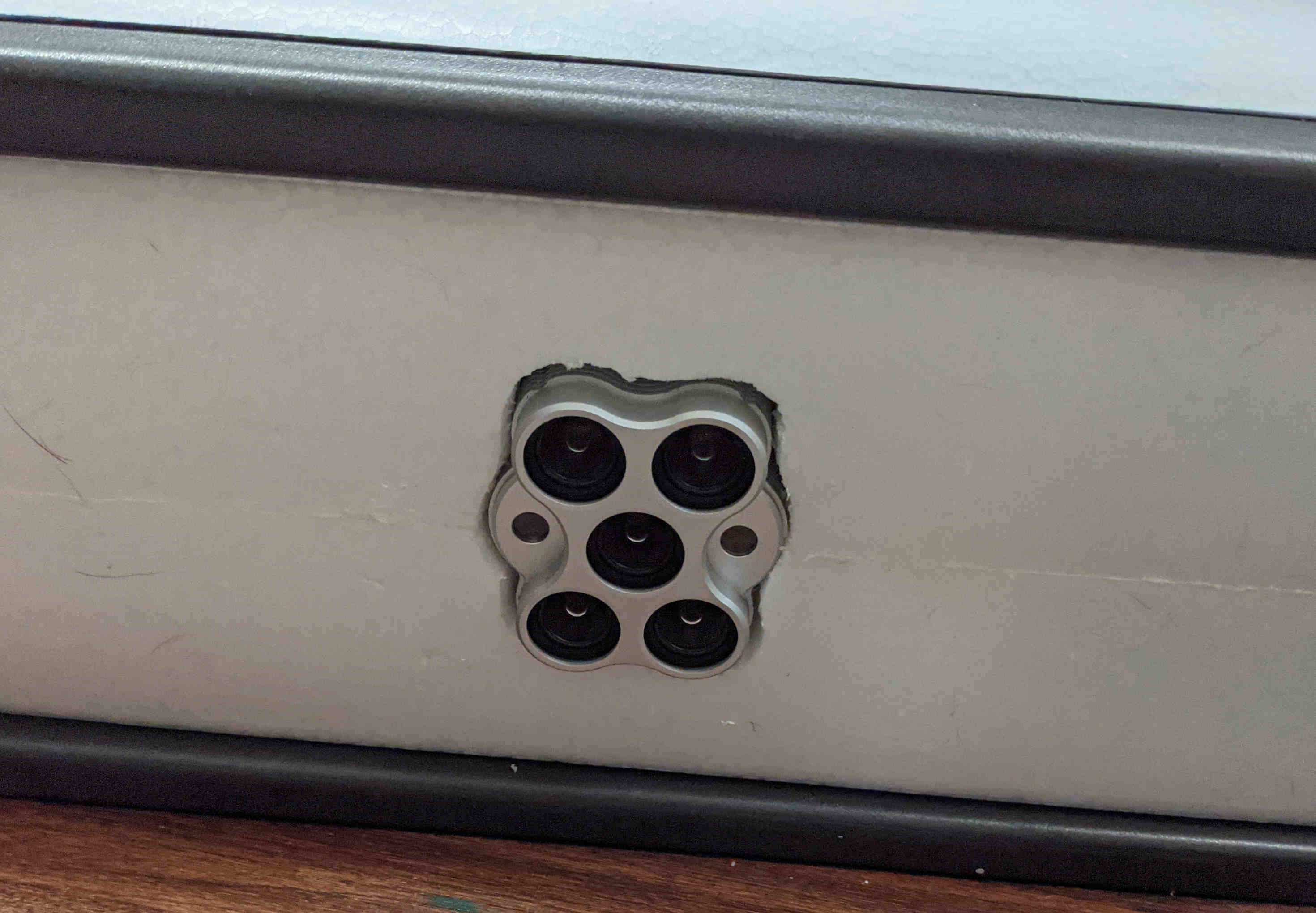
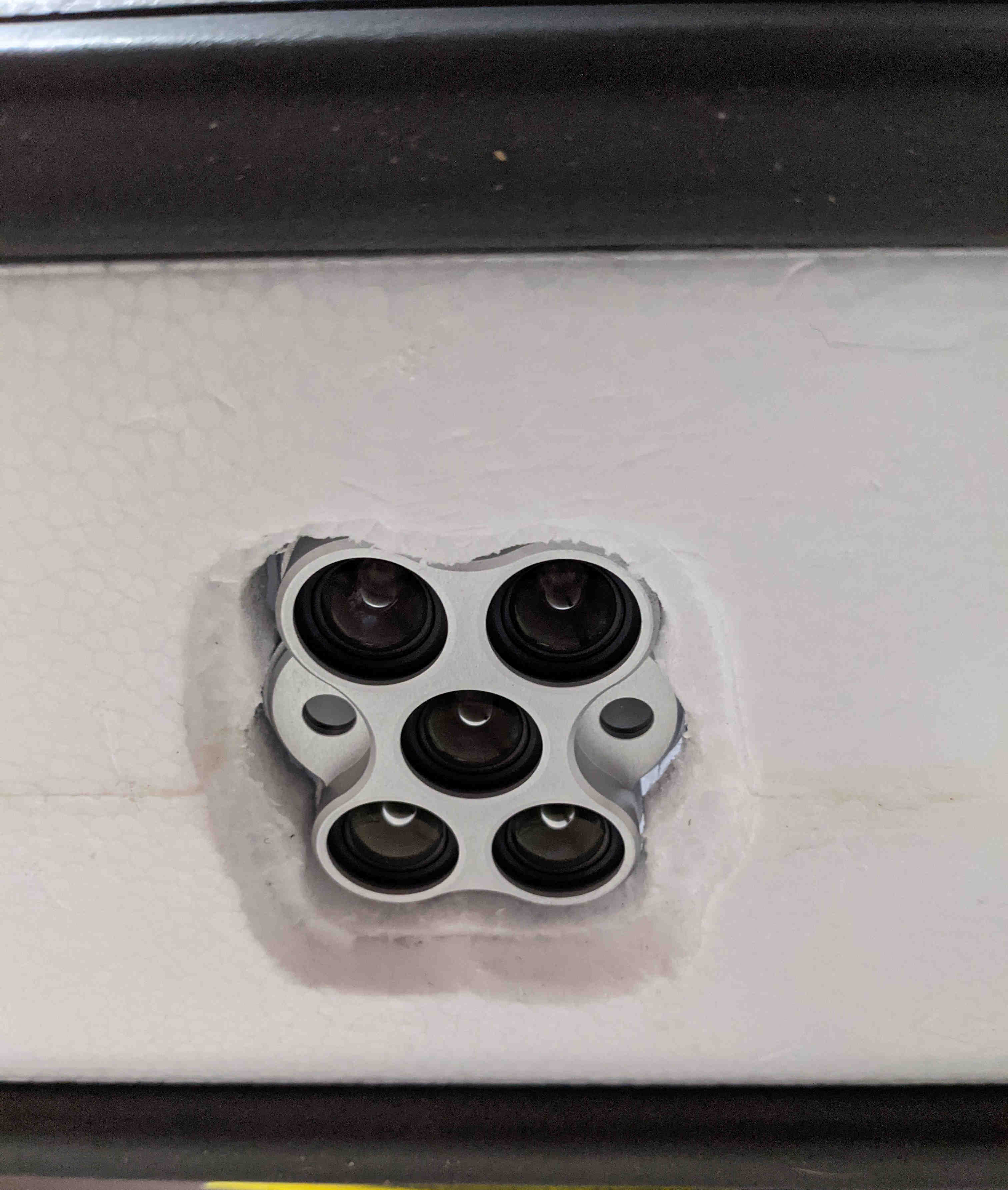
Mounting the multispectral camera against the belly of the fuselage made it protrude further than I was comfortable with. I added a 1.5 cm thick, medium-density foam to help recess the camera and provide a secure, padded, compressive mount for the camera.
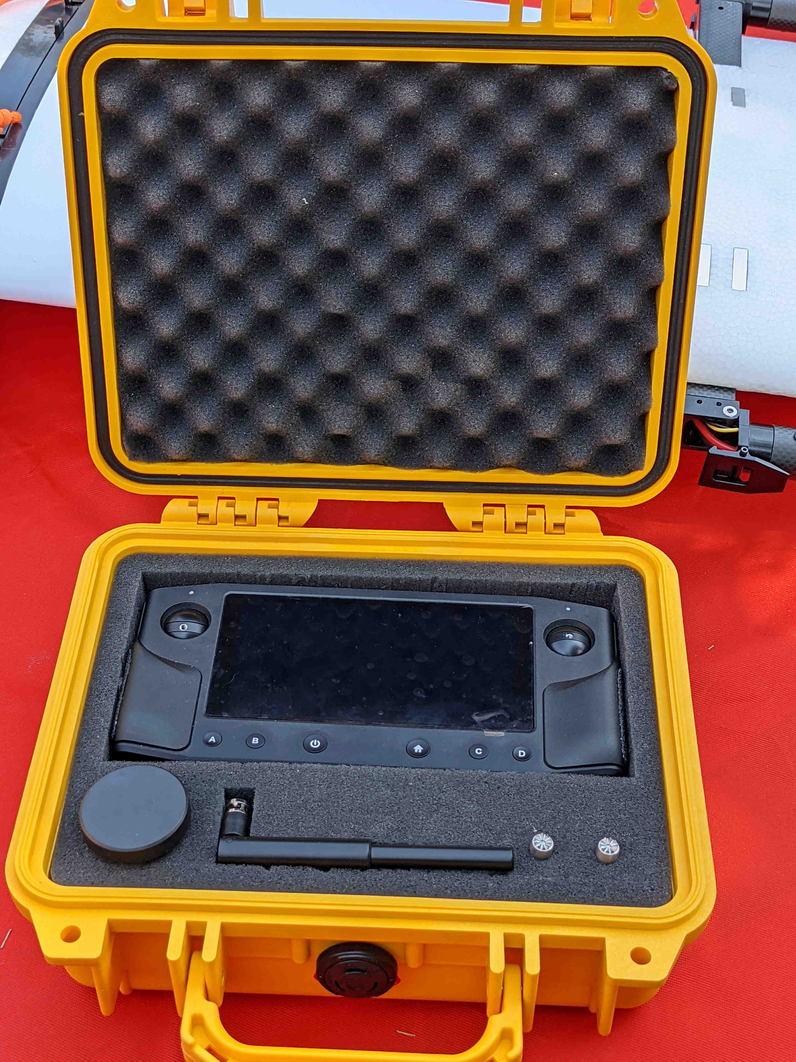
Herelink ground unit/controller fits nicely in a small Pelican case.
Bit of a firehose type of post, I partly apologize, but I’ve been busy in many things and haven’t been able to update progress!
Cheers,
Christian
Looking very good Christian.
Cheers
Jeff
Hi Christian,
Thanks for posting the photos. It looks like a pro build!
I like the way you utilized the underside of the hatches. You have more “stuff” inside your Fighter but it still fit well.
How did you end up securing the receiver hatch? I had to access mine a few times and got tired with removing the four screws so I ended up taping it with white duct tape. I would have preferred it if MFE used a latch design on all the hatches.
Cheers!
Thanks Greg. Somehow it all fit and miraculously doesn’t look like a complete Mickey Mouse job. ![]()
I just used the default MFE method with screws. Fortunately, I don’t need regular access to this compartment.
Still need to hookup the ViFly Finder unit and apply the covering film on the foam once electronics are GTG if no further body modifications are required.
Cheers,
Christian
Wow! What a fantastic update! Thank you for sharing so many photos with us.
I’m very curious about the multispectral camera. Did I miss a post where you provided details about the camera? If not, I’m hoping you’ll share some of the details.
I have a “RTF” version of the Freeman on the way. (I think “RTF” just means it includes motors ESCs and and servos.) I will likely try putting together the Freeman kit which includes all motors and ESCs before I do much more work on my Fighter.
Thanks again for the great update.
Edit: After a bit of research, I think the camera is this (or similar):
No worries! It’s not like it is some trade secret and I know that pictures help more than text alone for most. Happy to contribute to the community and help others with their builds since I have gained a lot of knowledge here.
Yes, it is the Micasense Altum multispectral camera in my Fighter build. My previous build used a Micasense Rededge MX which is much smaller and lighter. One thing to be aware of is that the Altum thermal band goes through a recalibration every 5 minutes or 2 degrees C change (https://support.micasense.com/hc/en-us/articles/360036377834-Altum-Thermal-Band-FAQ). The recalibration takes approx. 3 seconds which isn’t terrible unless it’s in the middle of a flight line resulting in a data gap in all bands captured.
Currently I am working on the MAVLink communications (bit of a learning curve) to command when the recalibrations occur. Ideally, I would like to have recalibration take place when the VTOL is making a turn between its flight lines. I haven’t tested if turning off the thermal band during image capture disables recalibrations completely. Either way, I will need to control the process for missions.
Cheers,
Christian
Hi Greg,
Just wondering, in your experience with the FrSky (primary and satellite) receiver pair that you use in your Fighter, in conjunction with your Horus X10S, what would be the maximum range that you would expect to see to maintain a reliable RSSI connection and retain the primary Tx control of your aircraft? Have you ever tested these limits to invoke a (real) loss of Tx failsafe in a flight?
I am thinking FrSky X8R and XM+ combo (I have spares in hand already)…or do you have any other recommendations on FrSky long range receivers (with telemetry)? My Horus is X10S Express so has ACCST and ACCESS.
I know that there are many variables at play here, but just trying to get an idea of what to expect with regards to a realistic and reliable maximum range of this receiver combo, versus using the theoretical (peace of mind) 40Km Tx and telemetry control range (not that I will be using that range anyway) of the RF Designs TX MOD in the Horus external module bay.
If I used these receivers for primary Tx (and the FrSky telemetry back to the Horus), I would still have the backup of a pair of RFD900x in the standard configuration for coms round tripping via Mission Planner…
My other option is to use the TXMOD in the Horus’ module bay and provide Tx through 16 channels of PPM from this and output from the airside RFD900x to the Pixhhawk RCIn so I have all in one control and telemetry/coms to/from mission planner (wifi to PC from TXMOD) etc and get the benefits of the extended range…however, then there is the potential downside risk of having both systems operating from the one Tx unit…ie in the unlikely event to lose the Tx power for example - both systems are down. Fall-back to failsafe but no coms at all…
Further to this, would it be possible to use the RFD TXMOD as the primary Tx control and coms to Mission Planner and then SBUS/Sport back out to X8R to enable the FrSky telemetry to the Horus as well - assuming that is still within RSSI range?
Anyone else reading this post - please feel free to add your thoughts. and experiences
My Fighter arrived - China to Australia in about two weeks…which is quite a reasonable time frame in our current worldwide logistics climate - quite a hole pierced through the bottom of the cardboard carton but thankfully no broken aircraft parts - just some small repairs to restore the polystyrene carrier…and only a few small compressions and scratches to the airframe parts - so overall a successful journey…I have read of others having various problems with big delays and various levels of damage (it is always a bit of a gamble and I have had my share of problems with other deliveries) however I thought I should share this positive experience.
Cheers
Jeff
Hi Jeff,
The FrSky radio link is bi-directional so you can get warnings for low RSSI and SIGNAL LOST. These can be using the default values on the transmitter setup or customized for your own preference. The manufacturer spec for the Taranis X9D and X8R link is 4921’ (1.5 km). I’m not sure if the Horus changes that but it does allow for a better external antenna to be mounted. I don’t think the redundant receiver extends the range but rather makes the link more solid from all plane angles of the radio link. I have not tested a Tx. failsafe but only a loss of sight failsafe using the RTL mode. That was scary enough. I have flown planes until they are just dots but I’ll typically fly line of sight, even when mapping.
I am still using ACCST because I have had no issues with it over the years and rely on Ardupilot telemetry over the FrSky Sport using Yaapu. My second telemetry link is the normal 3DR link at 900MHz. Sometimes, I use an RFD900 link at the base station which gives you something like a 5 mile (9km) coverage.
When using the RFD TXMOD, you are already using a PPM stream to the flight controller to control the radio functions so you cannot have a secondary SBUS connection.
Glad your Fighter arrived in relative safety.
Cheers!
Thanks Greg,
Great info.
I will probably go down the route of the FrSky Receiver and Satellite as my primary Tx control although maybe try some of the Archer Access offerings for which the range is stated as >2km. Plenty of range for VLOS flying.
Cheers
Jeff
For choosing wire sizes on wiring harnesses I found this site to be helpful:
https://dronelab.se/siliconewire.html
Cheers,
Christian
After some consideration, I have now decided to go for 12s and ordered the corresponding motors in China.
This is associated with higher acquisition costs, but the aging of the batteries should be lower compared with 6s, since the current per Li-cell is significantly lower.
I am not sure yet which ESCs I will take and also not yet whether I will install separate batteries for the quad motors. The latter I want to make dependent on the current when hovering and of course on what @Christian_H will report.
The RC remote control and limited MAVlink telemetry will run via TBS-Crossfire (https://www.team-blacksheep.com/products/prod:crossfire_tx). A second MAVlink connection will be installed via LTE 4G with a raspberry and UAVcast software (https://uavmatrix.com/product/uavcast-pro/). Both had been successfully installed in the Mini Talon Quad.Since there is enough space, a LIDAR altimeter and a RTK GPS will go in, so that Next summer the Fighter should be able to drop a 6 pack Budweiser with centimeter accuracy 
Cheers !
Rolf
Hi Rolf,
I like your Budweiser goal! Perhaps there is a new market to compete with Amazon.
The current draw on a 6s setup doesn’t seem bothersome. With all 5 of my motors on for a transition (worst case), the current is still under 100 amps on a 6s, 21AH pack that can deliver 630 amps continuous. The duty cycle for this is very low.
I haven’t found a use case yet for flying with RTK so I am interested in what brand you chose for your setup. My M8N GPS units all seem to work within a few feet to a yard or meter from take-off to landing. Perhaps it may depend upon your location but I am not certain. I am looking at this NEO-M9N receiver with MultiPatch antenna from the GNSS Store. The M8N modules I bought from them years ago are still working fine.
I tried a test with the Matek M9N-5883 NEO-M9N GPS Module on my Pixracer 250mm quad and it worked quite well. I would like to hear your thoughts on using an M9N module versus an RTK system.
Cheers!
Hi Greg,
Thanks for your information on the maximum current flow with 6s.
About the RTK GPS:
It is a u-blox F9P from Ardusimpl: the simpleRTKBLite (https://www.ardusimple.com/product/simplertk2blite/ ) with Helix antenna (https://www.ardusimple.com/product/helical-antenna/ ) , so far mounted on a small quadcopter.
Without correction signal, M9N and F9P are certainly not far apart.
I expect that the Fighter will really land with decimeter accuracy and not with “accuracy” of several meters when landing automatically.
Cheers!
Hi Rolf,
I’m very interested in range finder altimeter, particulary what find of forward offset you would use and altitudes you intend to fly at. I have a use case for flying a a set height above terrain. My plan was to fly the mission twice. First time to map in RTK and upload custom GEOTIFF and then fly the precise altitude using terrain follow in MP.
Steve
Hi Steven
I have used the rangefinder altimeter in fixed-wing aircraft only for automatic landing. LIDARs with a range of a few meters are sufficient to define the flair point exactly above the runway. I did not use it for terrain following. In the fighter, the LIDAR should also point vertically down and show the Q_LAND_FINAL_ALT exactly above ground.
Rolf
Thanks Rolf for the clarity. Looks like I’ll fly the mission twice.
Hello @GregCovey, @Rolf,
Finally I also just put order on this Fighter. I have important question about PID tuning of the plane mode, especially for Roll and Pitch… Based on default parameter of the plane FW 4.09 , value of the basic PID value for Roll P:1.0, Pitch 1.0 (PID of the Plane mode). I checked that last time you did posting “Gregparam3” file (CMIW), and value of those parameter is 1.2xxxxz
My question is, did you do Autotune (plane mode)?? Or do you think that default PID setting is good enough ?? Could you share your latest parameter (stable in plane mode)…Thank you…
Hi Tony,
I didn’t use the default PIDs and I didn’t use Autotune. MFE provides the PIDs in their on-line documentation here. I used their PIDs (copied into my .param file) and they worked great for both hover and forward flight modes.
Cheers!
@GregCovey,
Thank you very much… I have checked the parameter, and found it is not much different than default PID of the FW 4.09 …I also tried similar parameter for my previous VTOL, and it work good. I am curious if anybody has done Autotune in Plane mode.