Fighter VTOL 4+1 fixed wing

For now, I’m using the Nimbus VTOL as a test bed until the Fighter VTOL has been tested and I mount the gimbal base. I also needed to buy a Premium Micro HDMI High Speed Male To HDMI Male Cable for about $9.

The GoPro Hero 7 automatically inverts the image, if needed, on powerup. The analog video monitor was pretty good although it was a bit dark inside for a great image. I tested 1080p and 2.7K resolutions at 60fps. Both use the 16:9 aspect ratio. It looks like the latch for the micro HDMI and USB ports can be removed, if desired.

1 Like

I love this frame, I have experience in flying drones, but I have no experience in flying airplanes (only simulators), I would like to have a vtol plane like the fighter but I’m afraid of destroying it on the first flight. How difficult is the transition from flying drones to vtol? Do you recommend starting with a smaller vtol plane? Where can I get the frame of the figther in america? because shipping costs from China are very high now

You can get a Convergence VTOL for $250 to get some stick time and “feel” for transitions from MC (multicopter) to FW (fixed wing) then back to MC mode.

Good luck.

1 Like

Here is a Pan/Tilt gimbal I created for the GoPro Hero 7 Black using a $41 LOBOT PTZ mechanism from Banggood. A temporary wooden box hosted the testing but the target is the MFE Fighter 4+1 VTOL belly. The chirping is from my transmitter side levers passing center.

For initial testing, the waterproof GoPro case is secured to the gimbal with servo tape. Next, I’ll mount the back of the case to the metal pitch bracket with screws and load the GoPro H7 Black with Hypersmooth and Superview features. The camera automatically inverts the video, if needed. I may invert the camera case since it can be swapped 180 degrees. It would allow for the camera to be installed from inside the plane.

My goal is to create a stable video downlink with HD recording for mapping and searching.

So you’re essentially leaving out a gimbal by using stabilization on the Hero7 instead?

The large, heavy Fighter airframe should be stable enough in the air that you won’t have much of an issue.

Okay, so I think I have my propulsion system ready.

I had to go a slightly different route since getting electronic parts from MFE wasn’t an option and a 12s power system would be best for this VTOL build. I made my motor selections guided by the stock MFE part specs and incorporating the sensor payload. I chose Tmotor parts as I am familiar with them and the quality is generally top notch.

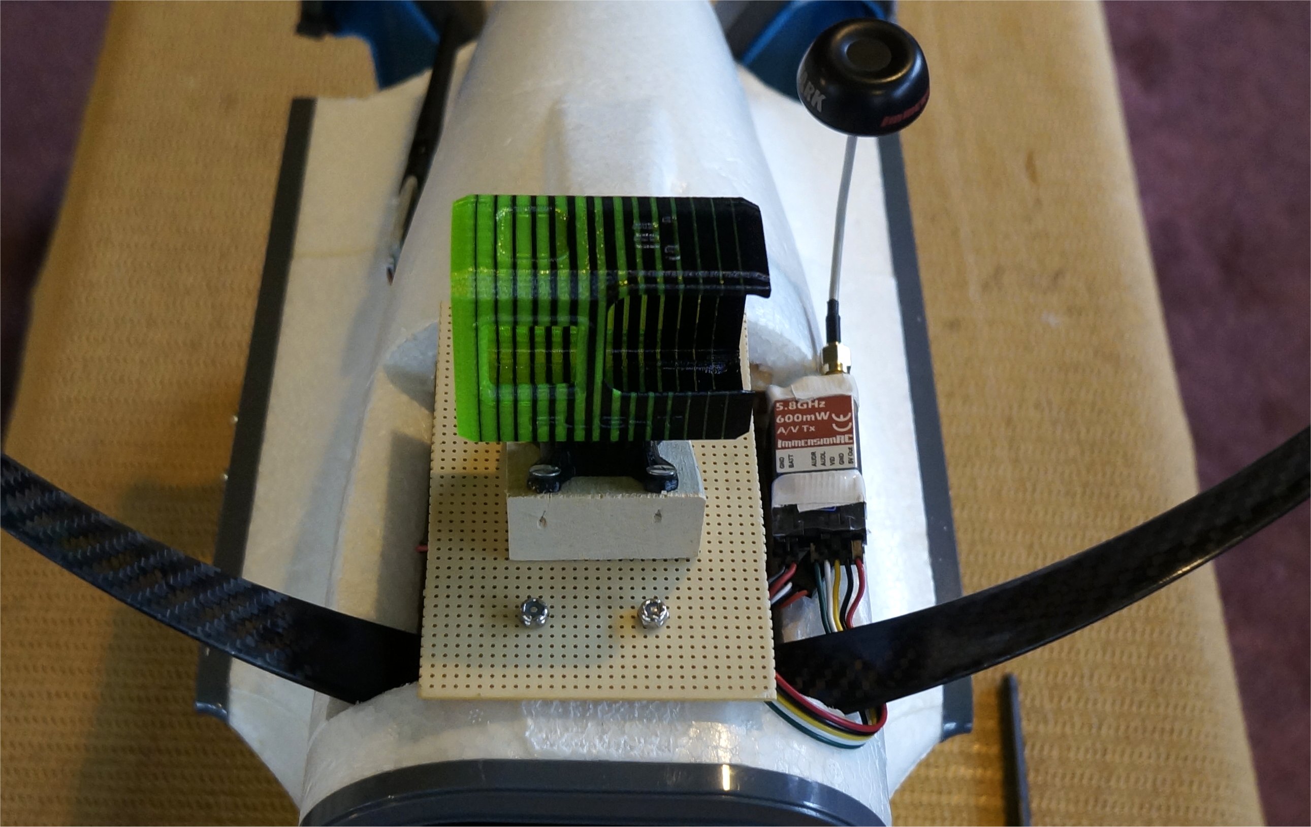
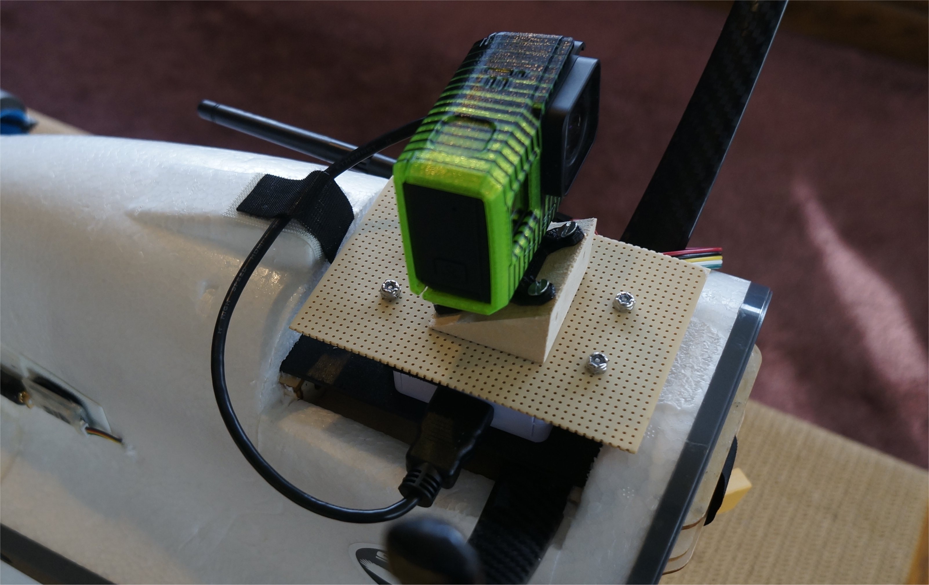
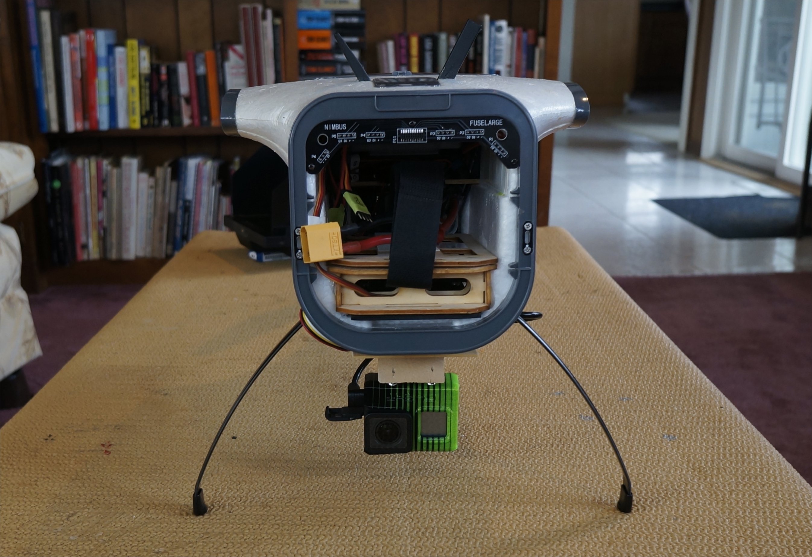
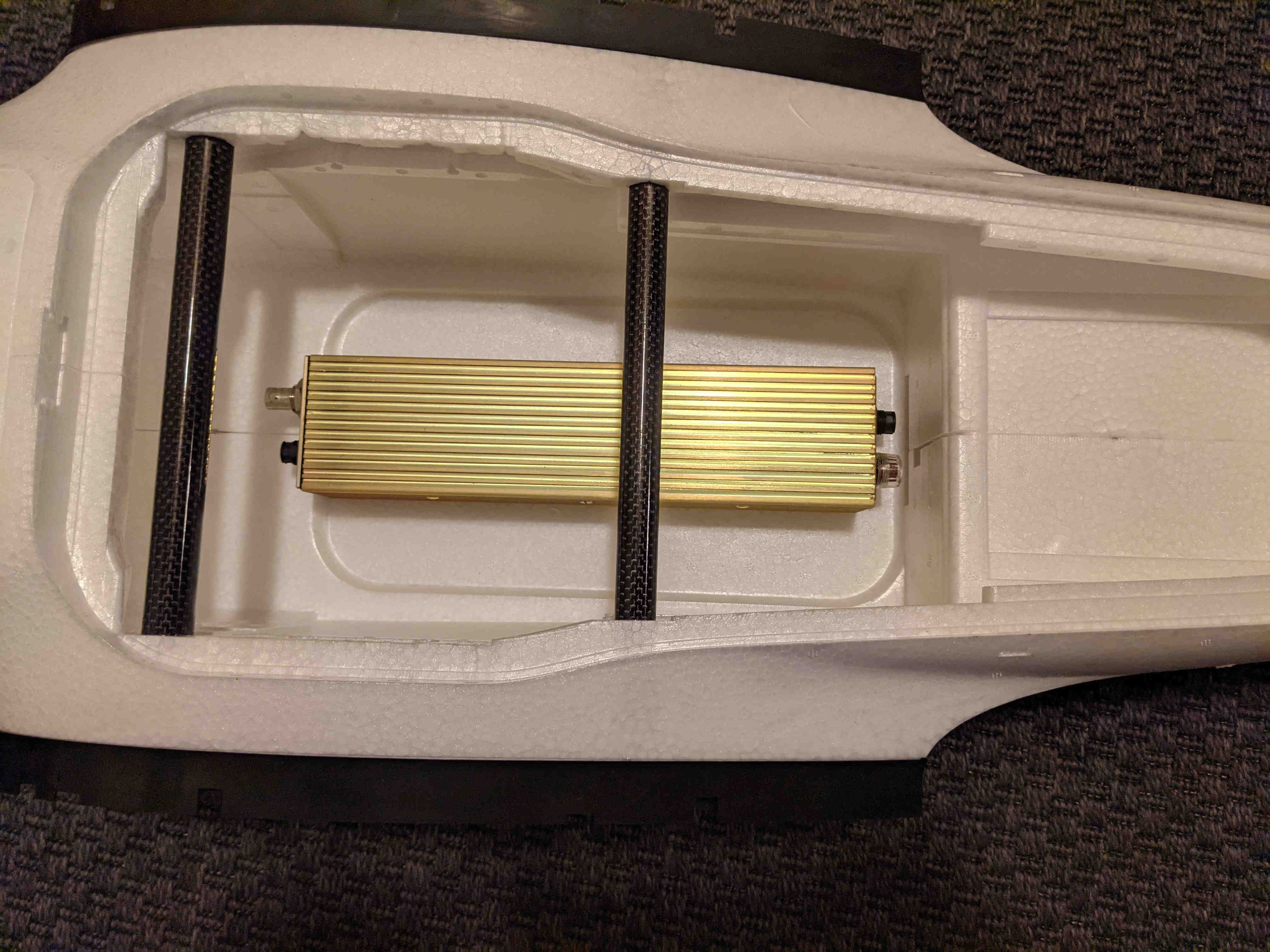
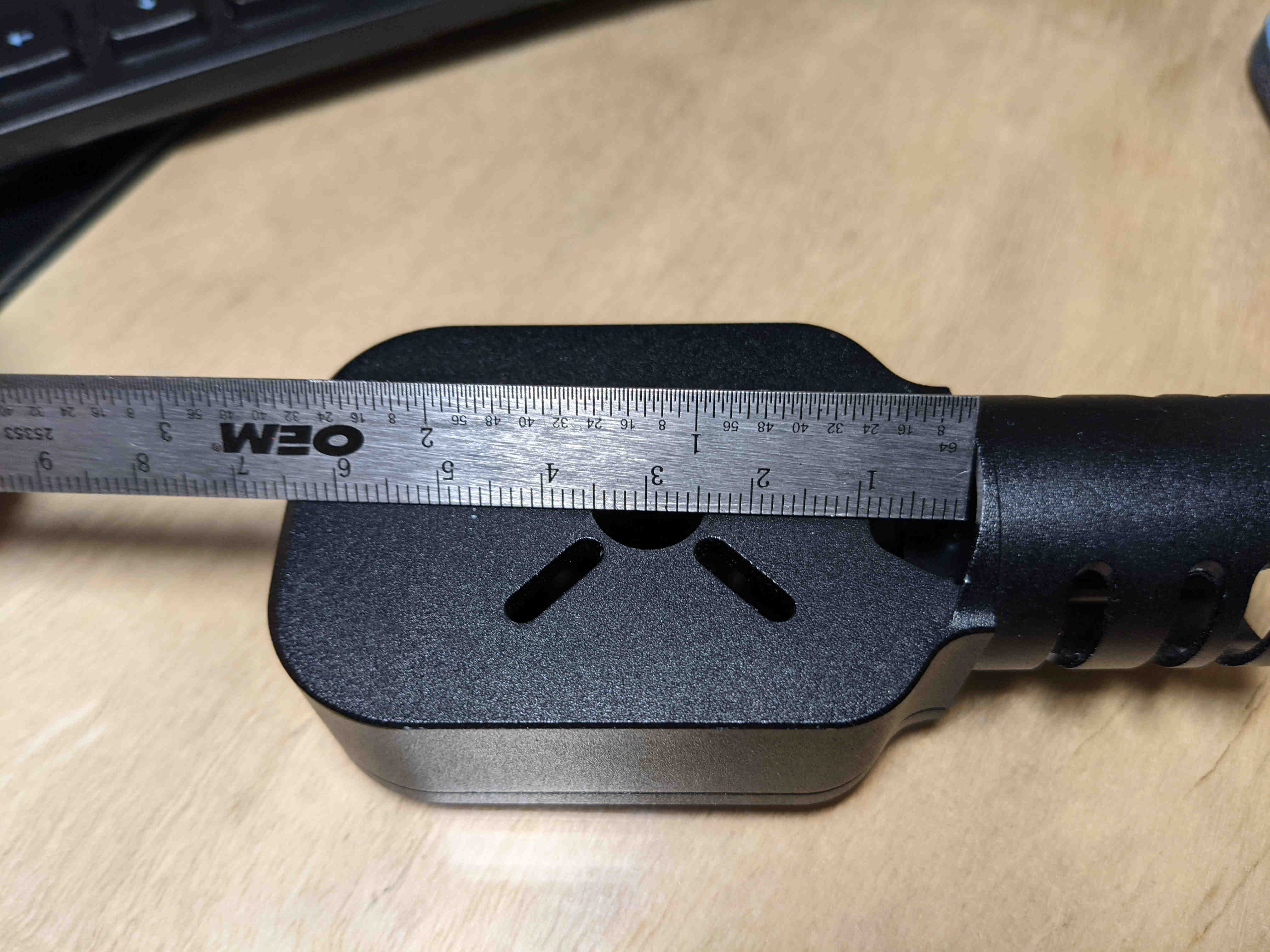
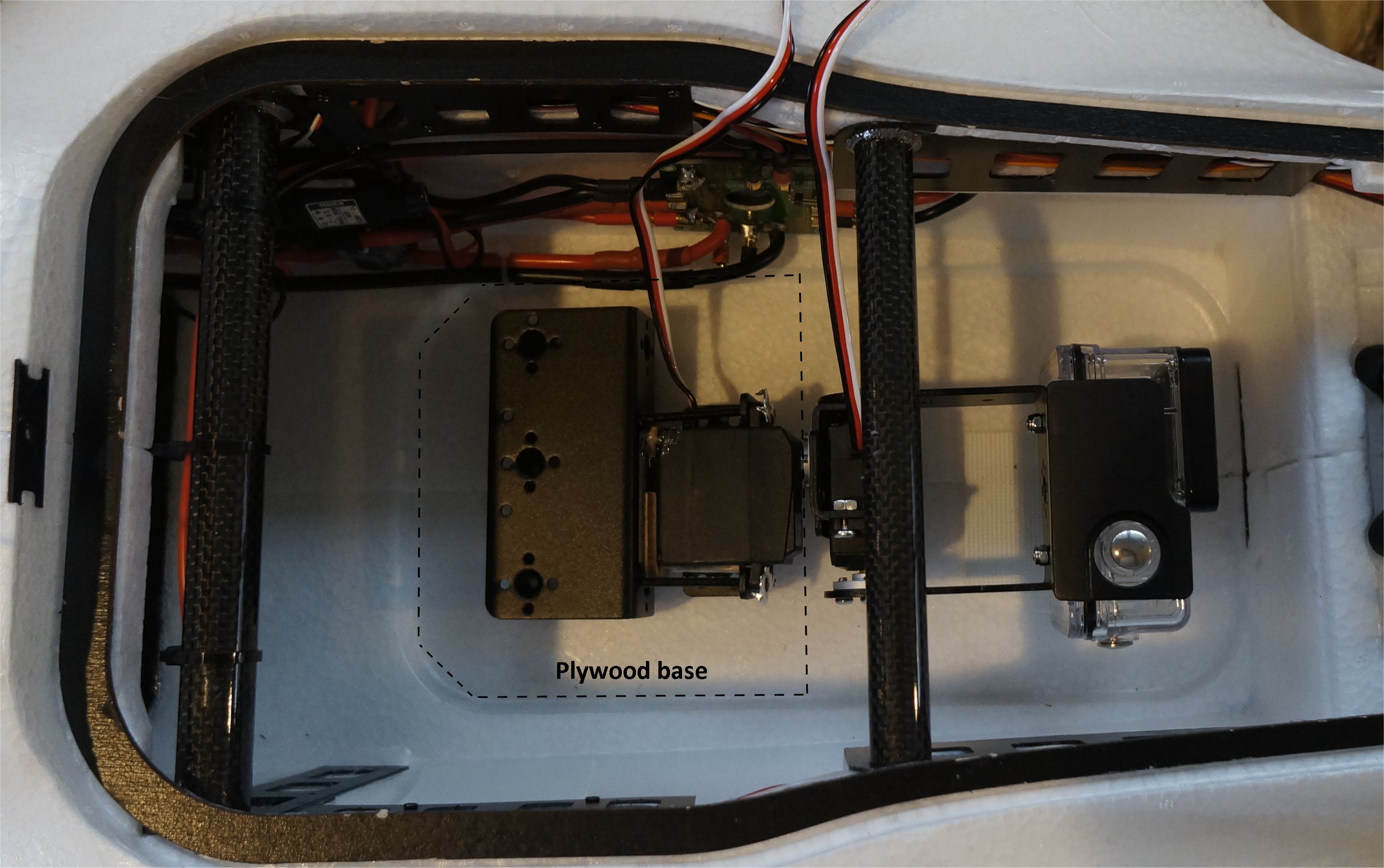
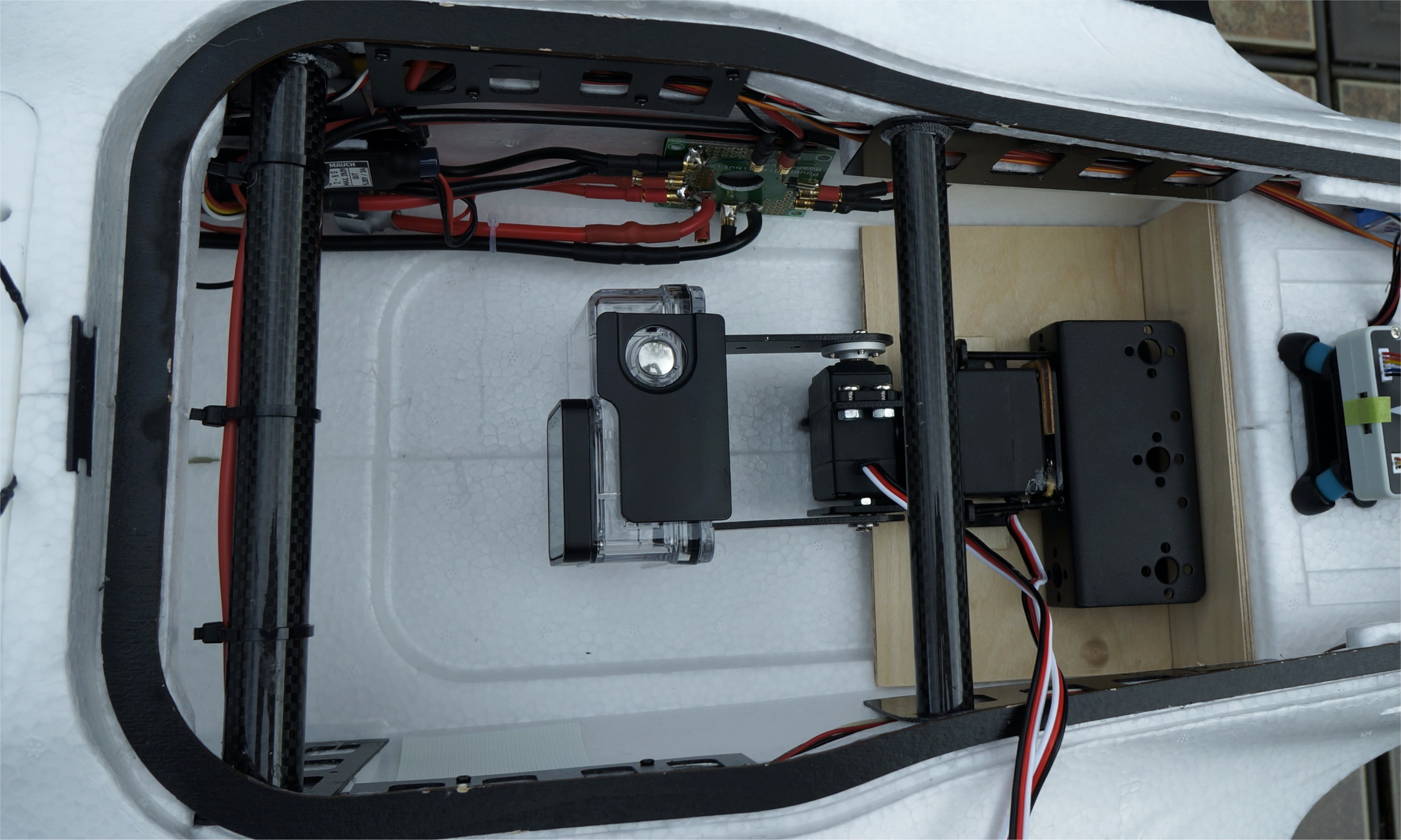
Main Sensor: The sensor payload (magnetometer) finally arrived which meant I could test fit components internally (see photo) and get an accurate, final weight of complete sensor (2040g). Original manufacturer spec was less than 1kg, however it was advisable to extend the cable in order to help mitigate any magnetic noise from the VTOL itself. I plan to attach the sensor box under the carbon wing spars and then also suspend the sensor cable from the spars near C.G. routing it through the belly. There will be approx 1.5kg of hanging mass so I want to secure it to the strongest part of the airframe.

VTOL motors: the MN601-S KV170 (https://store-en.tmotor.com/goods.php?id=457) are very close in spec to the stock MFE 5515KV170 (https://www.aliexpress.com/item/10000248221605.html) with slightly more thrust available (6.6kg vs. 6kg max with 21x6.3 prop) for slightly more current (21A max vs. 24.7A), lower internal resistance (115mOhms vs. 142mOhms), and 40g more weight. One issue I discovered is that the MFE motor mounts can only accommodate up to 60mm diameter flush-mounted motor due to the spacing of the mount holes and the tube clamp (MN601-S is 68.8mm diameter). I looked at modifying the mount, though I feel it would compromise the integrity since the motor mounting holes are reinforced and so you’d have to cut away at the tube clamp side. One slight modification (I don’t prefer) would be to add a spacer between the motor and the mount so the motor sits higher and clears the tube clamp. Fortunately, Tmotor offers this motor in an integrated kit which includes the mount, motor, and ESC. It is more expensive as you’re paying for simplicity (https://store-en.tmotor.com/goods.php?id=799).

Cruise motor: this one was a bit more tricky to match since for some reason MFE chose a 5015-KV210 (https://www.aliexpress.com/item/10000248218790.html) which has a large width stator, high torque, and low kV similar to the VTOL motors. The fixed wing cruise motors I’ve been researching are typically smaller width stators, high RPM, and lower thrust (any insight into why MFE chose a high torque motor on the Fighter for cruising is appreciated ). The opening in the nose cone of the Fighter has a diameter of 67mm. This meant, unfortunately, that the MN601S would not fit (68.8mm diameter) even though its specs were close to that of the stock MFE cruise motor aside from the RPM difference. Not to mention that it would need even more clearance if one did “open the cone” more since it is an outrunner motor. Would have been nice to have swap-able spares if all motors were the same.

That being said, I did find the option of the Tmotor AT4120 KV250 (https://store-en.tmotor.com/goods.php?id=826) which is a significantly more powerful motor than stock MFE (though 84g heavier), has half the internal resistance (76mOhms vs.147mOhms), and it is also 50 mm in diameter which fits in the nose cone hole. The bench test results posted on the AT4120 with a 16x8 prop show that 80% throttle produced 5kg of thrust at 24A (stock MFE has max thrust of 4.8kg at 43A). Max thrust of the AT4120 is 6.7kg at 46A, not that you’d want to be cruising at that high of throttle. There are other AT models with more thrust at higher Amps and bump up 50g in weight at each level up.

I plan to pair this cruise motor with an Alpha 60A HV ESC since that is what the VTOL motor kits will have and the AT4120 max current is 45A which means it follows the 75% rule of thumb for the ESC capacity.

Battery: MFE recommends 12s 16000mAh LiPo battery which can be achieved by using two 6s 16000mAh batteries in series (double voltage, same amperage). To keep it simple I’ll likely go with two 6s in series, however, I am considering using a double battery setup. In the double battery setup one battery has a higher discharge rating (30C) and is dedicated to the VTOL motors and the second battery with a low discharge rating (12C or 15C) and high capacity is used for cruise motor and all other electronics on board. The benefit of this system is that 1) you always know you have enough juice to land in hover mode and 2) you don’t risk uneccesary voltage sag on say a 12C high-capacity battery which could result in damaged cells, shortened battery life or worse, a crash. Appreciate any input on this arrangement.

RTF weight estimate: Using info from Greg’s hover test flights back in November, I adjusted for the differences in weight for my choice of motors, ESCs, battery, and payload. My all up weight (AUW) is 11.3kg (hypothetically powered by 2 Turnigy 6s, 16000mAh 12C LiPo’s) which is close to the max weight of 11.5kg listed by MFE for the Fighter VTOL. I think I’ll be okay here.

Quick Calculations: In hover mode, Greg estimated 15A per ESC (60A total) for his 7.45kg AUW. According to the MFE spec sheet, the 5515KV170 would generate 2kg thrust at 3.9A per motor (8kg thrust at 15.6A total) to lift Greg’s frame. If I needed 12kg of thrust to hover, the 5515KV170 would use close to 8A per motor (32A total) with an efficiency of 8g/W. The Tmotor MN601-S would use 7.5A per motor (30A total) with 8.5g/W efficiency so probably a wash with the exception that Tmotor has 10% more max thrust. Looks good here.

My top unknown currently is if the Fighter will be happy with a 1.5kg sling extending 5m below the plane using the Tmotor AT4120 KV250? AUW seems to be within MFE Fighter spec so really it will be the air drag force created by the sling that needs to be overcome. I have a little wiggle room if I need to step up the cruise motor one level or two.

Thoughts, suggestions, general comments?

Cheers,
Christian

1 Like

Yes, the finicky brushless gimbal…which cannot swing down below the fuselage like a servo driven gimbal. The two LOBOT LD-1501MG Digital Servo 17KG Metal Gear Servos that come with the assembly are very strong and precise. No noise or movement once the position is reached.

Make sure that your initial flight testing uses a dummy weight much like I did for my Sony NEX mapper. I still need to weigh my GoPro Pan/Tilt assembly.

Once you are happy with the hovering and flight characteristics, then you can experiment with extending various weights during flight.

Good luck!

1 Like

Gotcha. I was thinking more along the lines of aircraft roll when leveling/compensating in windy conditions. I do recall seeing “legs” on one of the VTOL parts lists for camera assemblies that extend below the fuselage.

For the multispectral camera I will need a gimbal to keep the lens angles fixed with some protrusion and likely some “legs” for launch/landing.

I’ll likely do a handful of tests without a payload so that I have some raw numbers of the system from the logs as this build will be carrying different payloads at times. I think FF will be the hardest to judge until I have the the sling dummy in place to see if the cruise motor is behaving how I want it to.

Thanks!

1 Like

The GoPro Pan/Tilt assembly fits in the Fighter belly nicely. On the left side, there will be an aircraft grade plywood base that will fill the well and disperse forces onto the thick area of the fuselage. On the right side, the opening for the GoPro camera and rotating arm can also be used by the Sony NEX mapping camera and foam block…whenever that arrives.

Note the reinforcement mods to the left servo. I filled the gaps (both back and bottom) with plywood pieces and then clamped the open side of the bracket down to the base plate on the left. Only one hole needed to be drilled. In this manner, the servo can no longer “bounce” as the camera swings 90 degrees. The waterproof case is now secured to the gimbal using two M3 flat head screws and nyloc nuts.

I may think about reversing the whole scheme so that the camera faces forward. The foam block would then be mounted on the left (forward) side.

1 Like

Hola, mi nombre es Alfredo de Argentina. Compre el kit Vtol. En configuracion 12s con baterias venom 22.000 mha. Y Placa Cuav V5 nano. Sensor mauch 100amper. y para telemetria y control RC estoy utilizando los modulos ORANGE lrs con el Firm de ULTIMATE LRS que vengo utilizando hace tiempo en mis aviones.
Ayer estuve intentando realizar el primer vuelo pero tuve problemas.
El marco lo tengo configurado en X eso es correcto o tendria que ser H.
El problema mas grande lo tengo en la guiñada, el avion tiende a rotar sobre su eje y no despega.
Ademas de inclinarce para adelante.
Agradezo alguna ayuda respecto a configuracion.

After further thought, I decided it was best to swap my mount around, especially when I discovered that I could then have a reinforced vertical wall. I made a few simple cuts into some 5-ply 1/8" plywood and the gimbal rests nicely. Next, I will come up with a way to attach and detach the gimbal easily.

The photo below also shows some green tape across the flash card reader opening on the Pixhawk flight controller. This is a safety measure to keep the card from ejecting on bad crashes. I have has it happen to me a few times so it seemed like an easy fix.

Hi Alfredo,

Welcome to the APM VTOL forums!

We have been using X frame where Q_FRAME_TYPE = 1. Several things can be causing your plane to rotate and lean forward. Compass interference while the quad motors are running is a possibility. Be sure that your compass is calibrated and your level has been set when sitting on the rubber runners on a level surface. If you could post a .BIN file that would be best.

Cheers and Happy New Year!

Hola alfredo

¡Bienvenido a los foros de APM VTOL!

Hemos estado usando un marco X donde Q_FRAME_TYPE = 1. Varias cosas pueden estar causando que su avión gire y se incline hacia adelante. La interferencia de la brújula mientras los motores cuádruples están funcionando es una posibilidad. Asegúrese de que su brújula esté calibrada y su nivel se haya establecido cuando esté sentado sobre los corredores de goma en una superficie nivelada. Si pudiera publicar un archivo .BIN sería lo mejor.

¡Salud y feliz año nuevo!


Voy a extraer el log y lo publicó. Lo que noto en el despegue no sé si se alcanza a ver en la foto es que el motor delantero izquierdo tiene mucha menos potencia que los demás. Se ve en la barra que no flexiona como las demás…

Otra cosa, tengo los motores totalmente perpendiculares. O sea sin ninguna inclinacion. esto tiene que ser asi, por que habia leido que si se tiene problemas con el YAW hay que inclinarlos hacia algun lado.

It is possible that you are not taking off from level ground. Another possibility is that your quad motor ESCs are not all calibrated. Be sure to check the ACC level in your GCS on a level surface and try to take-off for the first time from a level surface. Lastly, check your CofG both front and back as well as laterally.

Good luck!

Es posible que no esté despegando desde un terreno llano. Otra posibilidad es que sus ESC de cuatro motores no estén todos calibrados. Asegúrese de verificar el nivel ACC en su GCS en una superficie nivelada e intente despegar por primera vez desde una superficie nivelada. Por último, revise su CofG tanto por delante como por detrás, así como lateralmente.

¡Buena suerte!

no comprendo que es el CofG? Centro de gravedad?

Yes, that is correct. Sometimes it is refered to as CG or CofG.

Si, eso es correcto. A veces se le conoce como CG o CofG.

I think this is the better option to stabilize the gimbal assembly and reinforce its attachment points. Looks like the gimbal mount is a U-channel? Maybe you could put a strip of wood on the vertical plywood so that it sits inside the channel then screw the gimbal mount to it? The other option is to get a piece of small angle aluminum then tap the mount so you can run a couple bolts with lock washers down into it or just use a bolt with a nut/washer. Even a locking cotter pin or ring pin could work if you set the angle aluminum in such a way that the gimbal mount is held vertically by friction. This way you don’t need tools to remove it.

Jeeze Greg, what kind of acrobatics are you attempting when the hard landings eject the SD card? haha