@GregCovey has done a great job with his threads and engaging community!
@Rolf I am creating a build with separate power for VTOL (LiPo) and the primary system with forward flight (Li-Ion) motivated by your “Doublebat” build and thread. Regardless the arrangement of primary vs. backup power vs. just voltage and current sensing, there still needs to be common signal if both are connected to the FC or some other component, correct? (simplest is an appropriate gauge wire connecting grounds between separate battery power systems)
Cheers and welcome to the forum. I look forward to learning from your experiences,
Christian
@Christian_H
My experience with 2 batteries on the quad VTOL has been positive, as long as you mainly use the quad motors only for takeoff and landing at the end of the cruise and take care that the quad batteries do not age too much.
As you write, a thick GND cable between the negative terminals of both battery systems is mandatory.
In the Mini-Talon I had no problems with the dual system, it worked technically flawlessly. Last winter it crashed during low-level flight because a servo on the V-tail broke (What was another reason to buy the Fighter with 2 servos for the elevators)
If you have a mission with frequent hovering, I would rather use a common power supply with as high voltage as possible (because of the then low current flow and thus lower load and aging of the battery).
If the calculated cost of battery aging is not an issue, I would go with the 12s system with one circuit.
This is precisely my setup and intention. I will have flights of 45-60 minutes with a short launch/landing.
The VTOL batteries use a 10 AWG (vs. smaller Li-Ion 12 AWG) which is what I plan to use for the common signal.
The lower current, load, and consequentially lower heat generated are all reasons I went with a 12s system for longevity. I also have a large payload to carry for some of my missions so 6s may have been under-powered.
I am using 6s in series (12s) for both VTOL and primary power which is more cost effective than a single 12s battery for each. Because of this, I do have to watch for one battery failing in the series hence the desire to use the VTOL power as a backup to the primary. The idea would be that if the primary power (Li-Ion) fails, the plane would switch to VTOL power/mode and I’d land immediately since it will only power the VTOL motors.
Thanks for confirming the common signal detail.
Cheers,
Christian
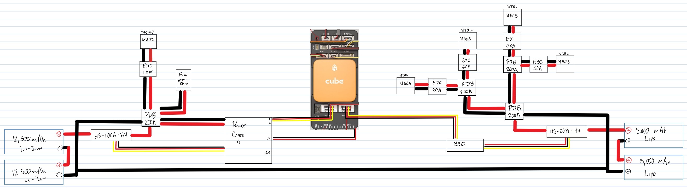
The primary power (12s Li-Ion) circuit will host the FC, servo rail, Cruise motor, Rx, and payload sensors either directly from the battery or via Mauch Power Cube (4 BEC outputs: 1 PM @ 5.35V, 1 backup PM @5.35V, 1 accessory @5.35V, 1 accessory @12V).
The VTOL power (12s LiPo) circuit will host the VTOL motors directly and potentially serve as backup FC power via a Mauch HYB-BEC 4-14s (1 BEC output: 1@5.35V) should one of the primary power circuit batteries fail or the primary BEC (Power Cube PM) fail.
The PDB’s are simple connection boards and are only required at the main electric hubs. The extra PDB in the VTOL motor chain might end up a splice solder connection to save weight.
Thanks for your responses - they are very helpful. Also very interesting to see your wiring diagram. Thanks for sharing.
I don’t have time to properly respond right now but thought I should at least attach my draft component layout options that I put together a few weeks ago. Keep in mind these were just basic ideas and will need refinement to get them to something that resembles a sensible final plan. Now that I have seen your and Rolf’s layouts, it is time to do some editing to refine my layout…Your comments on them would be welcomed. Do you think the third battery idea is valid or just introducing more complexity and weight?
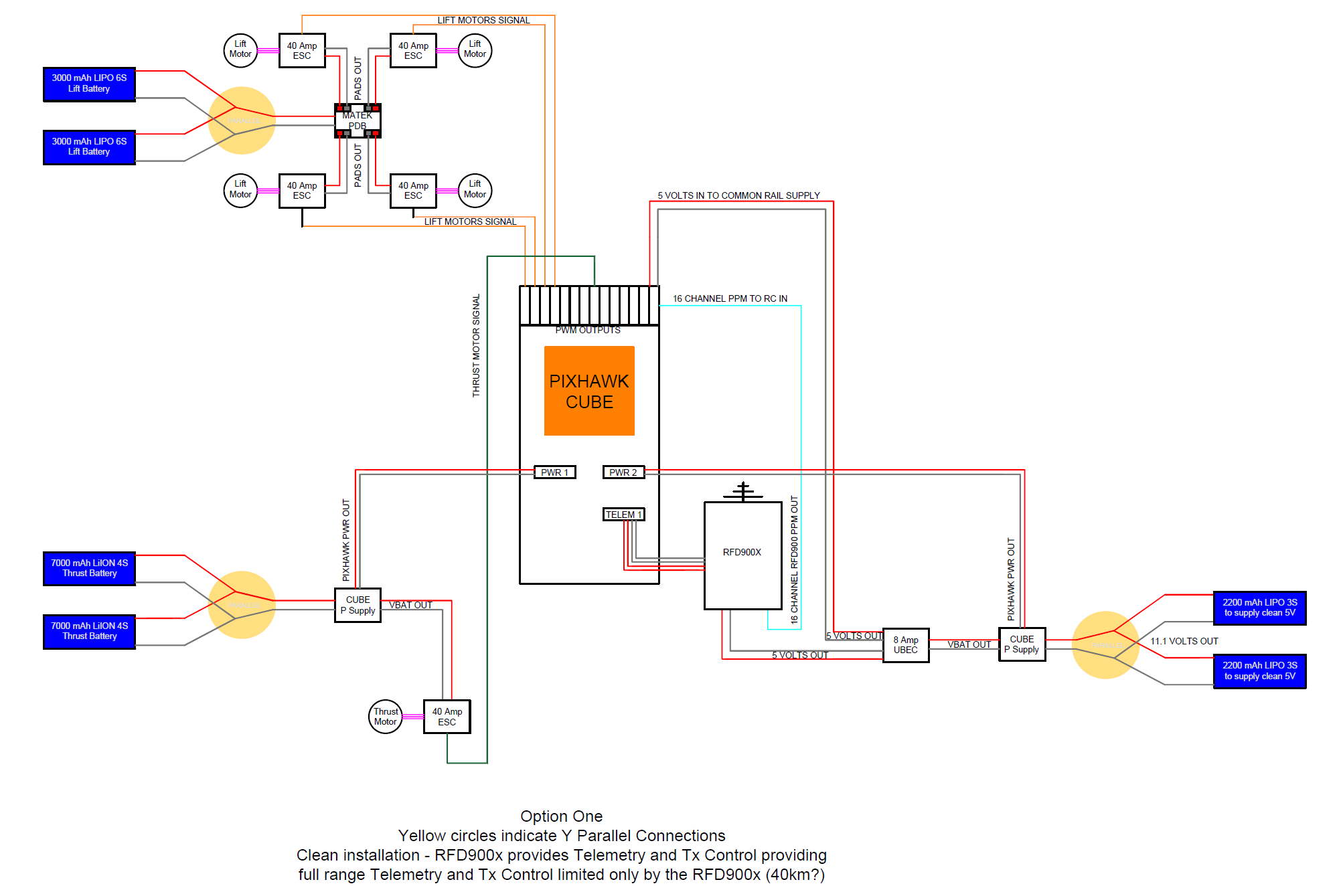
Option one uses only RFD900x to perform all Rx and Telem - This is using a Horus Radio with TX MOD from RFDesigns to control Tx/Rx and telem from the Horus Tx. wifi connected to laptop for Mission Planner persistent connection.
Option two - adds an FrSKY X8R receiver…which is going to limit ultimate range ability - but separates Rx ad telem functions to two separated components. This is using a pair of RFD900x’s in the normal way for telem and Horus radio talking to X8R for control.
I realise also that critical components such as sik radio and receiver should probably both be powered from a battery that is also vital to the system operation…ie the LIFT battery and the CRUISE Battery Circuits, and probably not the third auxiliary battery which should only be used for non-critical components, and as perhaps backup?
I really like your idea of being able to switch power sources and land if there is a problem with one of them. Maybe I should look at the Mauch power management modules?
We now have several reports of broken ailerons from different continents. I have not seen this problem but suspect the damage may have occurred during the more stringent customs inspections due to inappropriate handling by the inspector.
Perhaps a stiff cardboard shield can be placed over the ailerons and rudder to protect them once the box leaves the factory.
Having a dedicated battery for your Rx means that if all else fails, you will be able to find your plane!
On my previous build I had a TBS crossfire nano Rx that could take a 1s lipo battery to turn the Rx into a beacon when the main power failed so you could find your downed craft. I don’t have Rx power backup this time but am considering it when I set up for the other sensor load. I do have a VIFLY 2 as recommended by Greg and a “last known coordinate”.
Personally I’d go for simplicity in components and use just one Tx/Rx with the RF Designs Tx MOD for telem and control. I considered this exact option, however, the TX MOD units were out of stock when I was ordering parts. The crossfire Tx module had a bluetooth connection to Mission Planner which was really nice. It was also a bit slow to upload parameters via Mavlink but it worked almost flawlessly.
Use your most reliable battery for the Rx which is likely the same battery for your FC. Just don’t put it on a battery circuit that will deplete or fail before landing. Don’t forget to have a common signal connection (as Rolf confirmed) between battery circuits if a component has a shared connection (i.e., FC).
Mauch is the gold standard and the prices reflect that.
There is the sensor hub x2 is made for parallel battery connections (not series) and monitors the voltage difference between the 2 batteries. You can hook up a buzzer/alarm for close distance or possibly some other trigger on the FC to alert you of problems when not within earshot.
Mauch power cubes are nice in that you have all BEC’s in one package and redundancy. The downfall is that all of them hook up to the same battery circuit. So for backup power, use separate BEC’s.
With regards to the Common Ground between battery systems where they are connected to a shared component connection, I’m assuming this is to avoid ground loops within the system overall?
So I understand that I need to remove the ground loops from the system, If I end up running with the three battery approach though, I would potentially have 6S - 4S and 2S or 3S on each of the systems respectively and all sharing a common ground. Is that something that is achievable, or do they all need to be the same voltage?
Also just a quick question regarding the connectors throughout the systems from the batteries and on…I assume you are using XT-90 connectors or equivalent form a current handing perspective as a minimum?
I have been watching this thread over the last couple of weeks i think our setup may be of some interest, we have been flying the Fighter for a few months now its mainly used for for mapping missions so it is primarily built for endurance before that we were and still are flying Believers another very good mapping aircraft, it was purchased as a kit before the PNP versions became available, after a few discussions with Ben at 3DXR the lift motors we chose to go with were T-Motor 6007 KV160’s with built in ESC’s (Arm Kit) the props are MFE 20 x6.8 Carbon, the thrust motor is a T-Motor MN605-S KV170 with 19x10 APC Prop this combination has proved to be quite efficient it draws around 37 Amps in lift and cruises at 17m/s at an average of about 7 Amps that’s with a Take-off weight of 11.2Kg. Onboard we have a Cube Orange ADSB board a dual GPS setup with an Emlid M2 and HERE2 the airspeed sensor is a Matek UAVCAN DLVR-10 unit
For control/telem we use a Herelink with an FPV cam just for visual reference, an RFD868 radio is used as backup control/telem with a Laptop GCS running Mission Planner, The Emlid M2 is sent corrections over the RFD868 from a RS2 Base Unit connected to NTRIP the RTK connection has proved to be extremly reliable although we did have to play with the antenna placement to get it right, For most missions we have 2 sensors on board an RS1RMk2 42Mpx Camera with hotshoe event logging and a Multispectral with geotagging the sensors have their own power supplies
Our main setup is based on a 12s setup using 2 x Tattu 22000Mah 6S batteries all ancillaries and FC are powered from a single power module the only exception is the servo rail which has a seperate BEC, the single battery setup has never been an issue providing you manage it I use very short VTOL Takeoff’s typically around 10 seconds and the same with landings , I can cover 240 Acres in about an hour which is the extent of our permission and still have around 40% battery, with the sensors onboard the takeoff weight is 11.2Kg so its doing quite well. Of course it would be beneficial to use a separate lift/thrust system and we did consider it but there is just not enough space in this particular configuration
I have attached a link to a short video showing Takeoff and Transition, I am very pleased with the overall performance in VTOL and Fixed wing modes the transitions are surprisingly good, at the moment we are testing 4.1.0 Beta which has some very interesting improvements
I wanted to notify you about a design flaw in the VIFLY 2. If you let it sit for months without use, like I did over the winter months, it appears to be dead when you try to use it. It will no longer charge either. Apparently, the device draws a tiny amount of current just sitting around and then latches in a bad state.
The fix is to remove the shrink wrap, and touch a 5v supply (regulator or rx. pack) across the on-board battery tabs. This brings it back to life and you can then recharge it for use. I went a step further after recharging it and soldered an additional 150mAh pack in parallel to the on-board pack. This provides a much longer period before the batteries are drained.
Hi Jed,
Thanks for the detailed introduction and information on your 12s setup. I am curious to hear about your 4.1.0 Beta testing results so please give us a summary when you are finished. Our flying season here in Upstate NY has been poor this summer with lots of storms, rain, humidity, and wind. It feels like an extended spring season.
I compared our 6s and 12s current numbers and the differences appeared to be reasonable. My hover current was 60A on 6s and yours was 37A on 12s (or 74A on 6s). You have a heavier setup. My FF current was 17.5A at 19m/s and yours was 7A on 12s (or 14A on 6s) at 17m/s. You were flying slower on a more efficient setup. So the numbers seem to be in the same ballpark.
I see that you went with a black nose. It was a nice upgrade to the appearance!
Very nice setup! thanks for sharing the detail. I think the slower motors turning large props, especially on 12S makes for a very efficient VTOL. I have seen a video of Ben (3DXR) briefly mentioning the trend towards this as a preferred setup over higher KV and smaller props. He seems to live and breathe this stuff and appears to be very knowledgeable.
Can I ask about the connection that you have from your EMLID base to laptop? Do you use the RS2’s wifi hotspot to connect to the computer and then send the corrections out from the RF Designs radio base plugged straight in to the laptop USB with persistent connection to the airside RFD? Or is the RS2 cable connected physically to the laptop?
Combined with the Herelink which has a good control range also, that’s a very nice solution to to have long range control, FPV on the controller monitor, telemetry and NTRIP corrected data sent to the M2 onboard and no need for an EMLID LORA radio in the mix! Only using 1 of the RFD868 antenna’s or is the second one inside the fuselage?
Does the M2 connect to the CUBE carrier board, or is it just connected to the RFD868 and used independent of the FC and purely for data camera hotshoe logging?
And also what size battery are you using to independently power your sensors for your hour of flight?
7 amps in cruise seems amazingly good.
Finally - Do you fly your believers as 6S setup? I assume they are configured as belly landers? I am not far off building my first Believer which has sadly been sitting in its box for a very long time. Are you able to provide similar detail on how you have yours setup? It would be very helpful.
I like the video - very quick up and transition.
Apologies in advance for the barrage of questions…but I am very interested in the setup detail.
We use the Hotspot to connect the RS2 then RFD on USB
There is one external antenna and a stubby in the fuselage just incase someone forgets to connect the external
The M2 is connected to GPS1 and is used for Nav I know they don’t advise it but we do have a Here2 as backup it has never caused us any issues we get on average 24 Sats on the M2 and 17 on the Here2 GPS_AUTO_SWITCH is set to 1 choose best
We use Panasonic 3.7v 3200mah 18650 Li-ion cells 7 in total
The Believers are setup exactly the same but on 6S and we only carry one sensor we still get a reasonable 7/8 Amps in cruise
No problem anytime, we have quite a few hours on the fighter its a very good aircraft I cant think of anything else on the market at the moment that could replace it
Thanks for the tip Greg. I have some small 1s batteries (160mAh) that I will plan to hookup to the VIFLY so that I don’t have to worry about the primary depleting.
I have a gut feeling but I won’t venture a guess because I do not know for sure and it’s been a while since my electrical engineering for physics courses. @rolf might be able to answer definitively. This is something you want to make sure is wired up correctly unless you want to risk some “magic smoke.”
I have XT90 connectors for the VTOL LiPo battery hookups with everything else downstream soldered. The Li-Ion battery hookups are XT60 and should never reach 60 Amps so I should be ok there plus the XT90 plugs come at the expense of extra weight. The anti-spark connectors are a nice option, I might swap out later this fall.
Your setup is very similar to what I am working on (MTOW 11.4 kg). I’m glad to hear that it is working out for you thus far. I do find it curious that you use the same motor model for all of the motors on board. The MN605 is significantly lighter than the AT4130 that I am using but not nearly as powerful (mine is overbuilt intentionally). In hindsight, I would have gone for the integrated arm kits to save the hassle of installation on the VTOL motors.
How has your range been with the Herelink? Has it dropped out on any of your missions or have you pushed that limit? How was initial tuning on the heavy bird? Which parameter set do you use?
Photos of your build are much appreciated if you’re willing to share.
It’s very common for electronic systems to have multiple voltages. As others have said, you need a common ground.
Generally connecting the grounds of the batteries is a safe way to connect the grounds. It is certainly possible to connect grounds in a way which will burn out components. I learned this about 7 years ago when I destroyed a microcontroller by connecting the ground from a motor controller to a ground connection which wasn’t near where the motor was receiving its power. I described my problem in this thread on the Parallax forums. (It’s embarrassing to read my old comments. Those guys were so patient with me.)
My mistake would be like connecting the ground of the power connection to a UART ground on the flight controller. As long as you have the return grounds from large power items return to the same power junction used by the positive line, you should be fine.
A lot may hinge upon how and where things are grounded. Since you are using high-current devices, it’s important that the ground currents from them do not traverse through the logic portion of your circuit. IOW, the ground returns of all devices should be connected at a single point in such a way that that the currents from high-current devices do not return to the logic ground terminal but directly to the high-current ground return. High ground currents through your logic circuit could easily fry the Prop.
His comment applies to protecting flight controllers as much as it applies to protecting a Propeller microcontroller.
If you’re not sure about your particular setup, you could always post a diagram and photo of your planned wiring and someone here can take a look at it to make sure you’re not going to fry any components.
Thanks for the great information - it is very useful to have details of other members working examples.
Just a couple more questions…if i may?
Are you using the EMLID Tallysman antenna for the M2? I assume it is inside the fuse somewhere? Do you mount it on the recommended 100mm ground plane? Where do you mount it in relation to the camera position?
Have you ever used the Hex Here+ RTK ground base to send corrections to your Here 2/Here 3 - in addition to the EMLID RTK system?
If you were just powering the single sony camera and no other sensors - what in your opinion should be the Li-Ion configuration of the separate battery pack ie S and P configuration for V and mAh etc to ensure that it runs for at least the entire mission?
Are you able of give me the specification of the motors, esc’s and props that you use in the Believers that you are using?
Thanks for your great information and links to follow up with my Common Ground question.
It is something that needs to be right otherwise yes there will potentially be $$ going up in smoke…
I checked out the freeman after your suggestion, but didn’t end up going down that route - instead just ordered a MFE Striver as my first Quadplane build - and rather than trying to covert my believer - set that up as a belly lander…I like the 4+1 configuration and at 7Kg the Striver should be ideal for my 6S setup…I will probably order a Fighter as well…and would set that up as a 12S to take advantage of all that it offers.
Thanks again for your great information with regards to the common ground question.
I have some good suggestions too from Duane and should seek Rolf’s advice as well…yes Magic Smoke can be expensive and very alarming to watch! I have fried some LED’s by over voltage, in the past but thankfully no expensive components - Yet! I always use a Smoke Stopper when I first plug in so hopefully that will at least catch some problems…
Thanks for the info on the connectors - I have XT-60’s and Deans etc on most of my Lipo’s so I was going to replace these all with XT-90 so I have consistent connections and so I don’t need to use adaptors on these…soldering downstream is a good idea to reduce points of failure and weight…it all adds up! anti-spark connectors would be good too.
Jeff, no worries. I’m happy to try and help save the head banging on the desk/wall of others if possible. I’ve been down many rabbit holes on this adventure.
Consistent connector size makes the charging easy.
I am using the stock connector size on the batteries since my battery circuits are in series (double voltage, same capacity, same current). If I were to connect in parallel then I’d consider upgrading the connections to handle the increase in current (i.e., if expecting constant flow at 60 Amps then I’d upgrade to XT90).
Just be sure to not cross the battery cables when removing and adding a new connector- it’s a quick lesson that you only need once! ha