Thank, Rolf.
I checked my Sony NEX manual and discovered that my sequencing for video record on/off was a bit wrong so I will know better next time. Live and learn…
Cheers!
Thank, Rolf.
I checked my Sony NEX manual and discovered that my sequencing for video record on/off was a bit wrong so I will know better next time. Live and learn…
Cheers!
Nice work Greg.
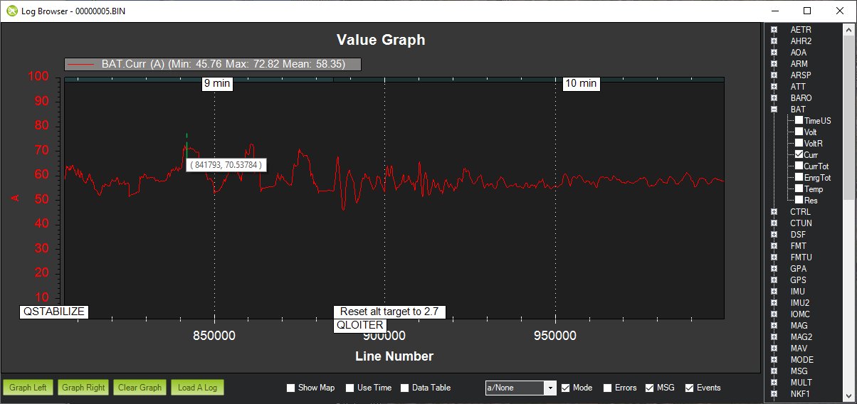
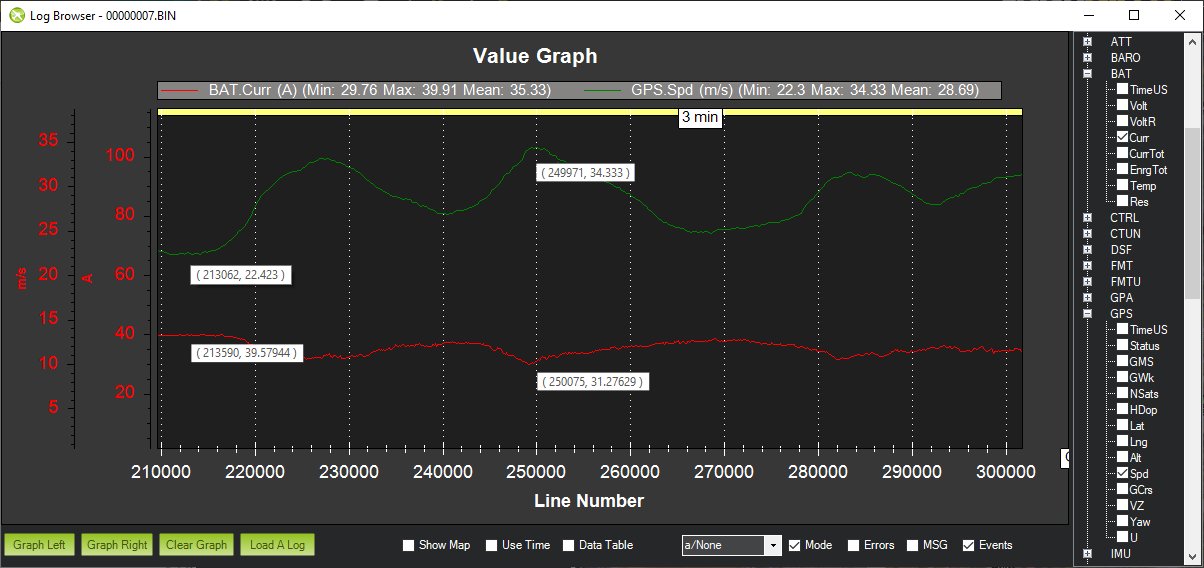
So it looks like your hover is ~60% throttle at 60 amps based on that theoretical(?) bench test plot. How many amps did you need for climbing? (I’m assuming it was a gentle climb)
Christian
Hi Christian,
Thanks, I sure wish my camera was recording but I’ll do it again soon. The first flying of the season is always a bit apprehensive for me so I did bring some other planes to shake off the rust. It’s actually quite early to fly for us here in Upstate NY but this Spring has been dryer and warmer than usual. My normal flying field is still closed to I drove about 50 minutes down to Canandaigua.
I did some climbs in QSTABILIZE mode and it looks like the current was around 70 amps. They were reasonably fast climbs, not crazy but it didn’t take long to get up there.
I know exactly what you mean with first of the season flights. 
70 amps is pretty low bump for the rig. I’m anxious to get my hover test in…
My third round of hover testing the MFE Fighter 4+1 VTOL worked great and so did the video camera this time. The testing was done using QLOITER mode.
My maiden flight of the MFE Fighter VTOL was uneventful as it worked very well. The initial PIDs supplied by MFE played a big part in the success of both hovering and flying.
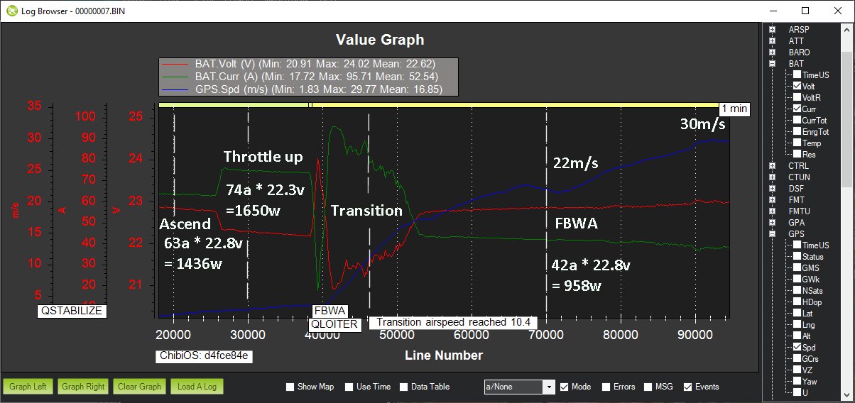
The transitions from QLOITER to FBWA and back appeared seamless. Flying in FBWA mode was steady and smooth. The initial transition tests were done at a safe height so the plane appears small in the video. I’ll grab the log soon and see how the forward flight power system performed. I didn’t use the air speed sensor but I can check that out too and plan on calibrating it on my next flight.
Congratulations on the successful tranistions. It is always impressive how systematically and according to plan you proceed.
Cheers!
LOL, thanks, Rolf! A good compliment from one who is also a perfectionist.
At the field, the guys were asking how I remember “all this stuff”. They just fly normal R/C planes. As you know, it comes from being an APM enthusiast for many years!
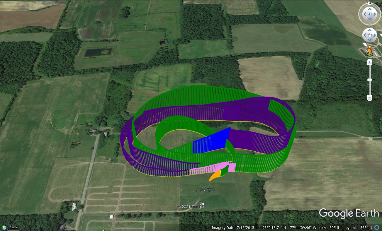
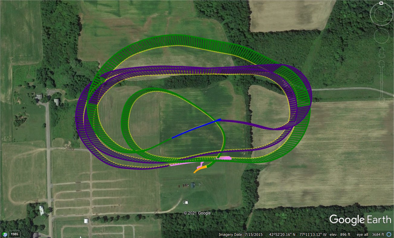
Here are a few flight path images from the log. Apparently, I was too far to the left and got reprimanded for flying into the “forbidden zone”, which is someone’s private property. I’ll have to increase my turning capability. I am so used to v-tail designs that I normally just increase the MIXING_GAIN but for a normal tail configuration, I will likely increase the SERVOx_MIN and SERVOx_MAX for aileron.
Cheers!
Another successful maiden. Great job, Greg. Thanks for sharing. I hope to have mine done in the next month. Similar results would be awesome.
Hi David,
Thanks! I hope that you will have better luck this time. As you can see, the MFE PIDs are working well so no fine tuning is needed during the initial testing. It can be done at a later time, if desired.
I did my usual “heavy throttle” maiden flight where I was flying too fast due to nerves and making sure the plane did not stall in front of the crowd of on-lookers. The Fighter is large and looks like it is flying much slower than it actually is. I prefer to have fewer people around when I am test flying a plane.
I was typically flying from 22m/s to 30+m/s as I focused more on how the plane controlled and bringing it lower as it kept wanting to rise with the speed. So my forward flight current is high and I will need to re-test in CRUISE mode while I calibrate the AS sensor. I plan to lower my ARSPD_FBW_MAX from 25 to 20 and leave my ARSPD_FBW_MIN at 10. This should provide a speed of 15m/s around mid-throttle in CRUISE and LOITER modes. I saw no dipping or altitude change by having the transition complete around 10m/s.
Hey Greg,
I am about to start wiring the fighter, so, of course, I reference your work. I noticed you are only bringing a single signal wire to each component. I’ve always thought you need a ground, so the signal wire has a reference. Do you have a common ground someplace or are you just plugging the single wire into the pixhawk?
Thanks,
Dave
Dave,
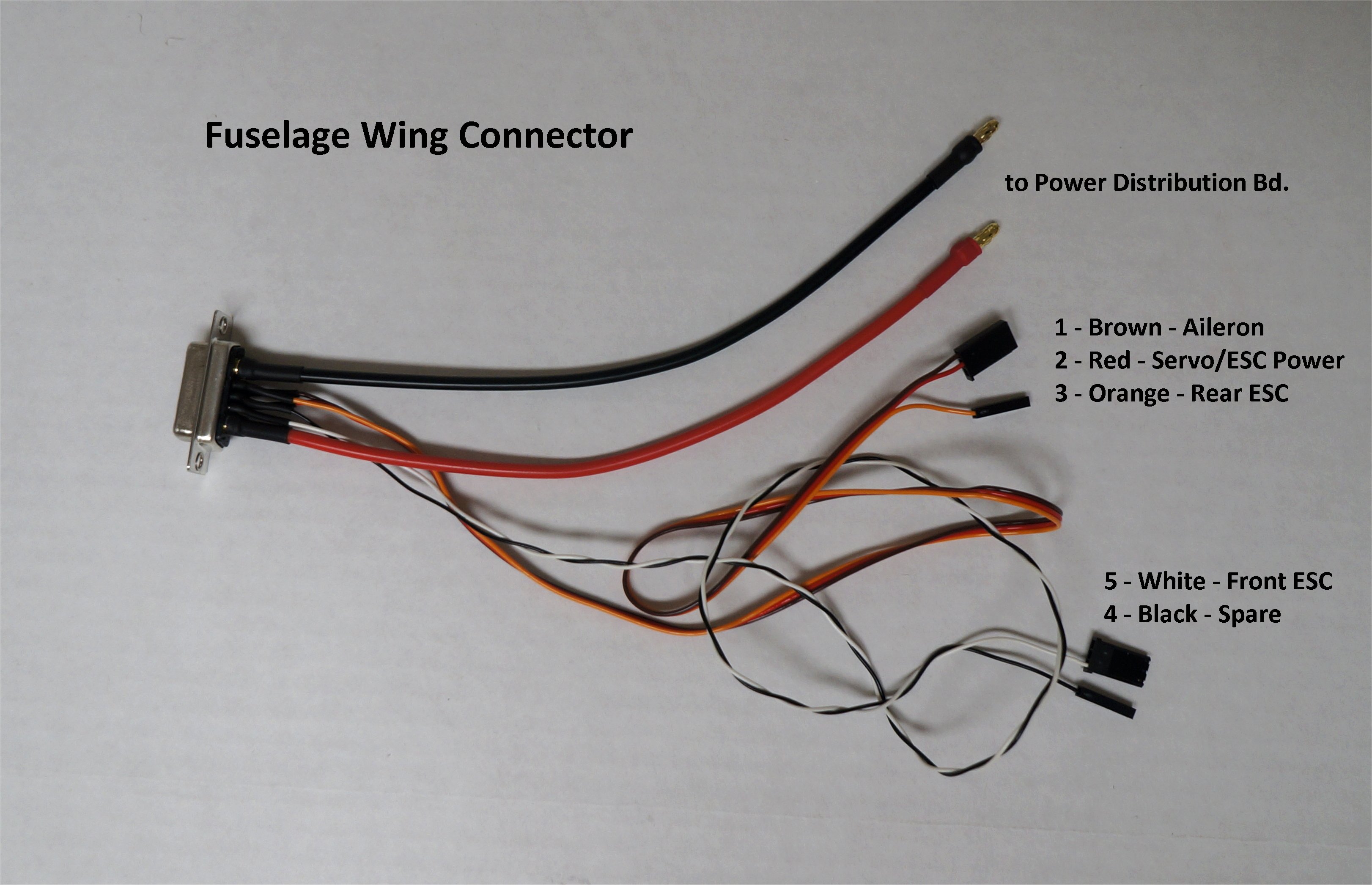
Yes, the common ground for the wing is the thicker black wire going to A1 (Battery -) pin on the connectors. Each component on the wing gets a ground connection to this line. Everything runs from the battery to the Power Distribution Board. The Pixhawk gets ground connections via the Mauch regulator and CC BEC back-up supply connected to the servo output pins. The individual lines from the Fuselage Wing Connector (shown below) don’t need their own ground lines so it reduces the number of wires needed to run to the Pixhawk.
Certainly, if you feel more comfortable using grounds, you can pick them up on the A1 pin of the connector.
Hey Christian_H,
I am starting to wire the fighter. I bought the same ESC as you did for the drive motor. But at 182 grams I am reconsidering my decision. It’s rated for 115 amps which is way too much. If I recall the drive engine should cruise around 10a with a max near 40 a. With this in mind, I am thinking about using the castle creation ESC you reference in this post. It’s about 1/3 of weight and more appropriately rated. Do you see any problems with using the Castle Creations ESC for the drive engine?
Thanks,
David
That is very similar to how I wired my Freeman. I just want to make sure I am doing things intelligently. I’d like to avoid another crash.
Thanks for your reply.
Dave
Hi David,
You might be okay with the CC ESC (Phoenix 40A?) but it will depend on the cruise motor. Which motor model did you decide on?
That 115A ESC is a beast at 182g, no doubt, but I think a good chunk of that is due to the heat sink and metal casing. The main reason I went with a TMotor ESC was for continuity as 12S ESCs are limited in selection and TMotor makes good parts. Another consideration is that I was able to get the ESC in a position that the CG is correct since I have a separate battery system for VTOL motors to shift weight toward the tail. I am building a heavy bird with MTOW near the MFE 11.5 kg max spec.
Cheers,
Christian
Hey Christian,
I went with the T-Motor AT4125 (250 KV). I plan on spinning a 1510 prop. My UAW shouldn’t exceed 8kg so I anticipate around 10a pull at 20m/s.
11.5 is a beast. How is your build progressing? Do you plan to use the PIDs provided by MFE for your maiden?
Thanks,
David
So when I asked TMotor about a recommended ESC for the AT4130 back in January they told me “the AT115A is recommended for this motor. Alpha ESC and flame ESC are not recommended as BEC not included.”
BEC has no bearing on the ESC choice for the motor as far as I can see. It’s just if you want to power other components then you have another low voltage supply. I believe at the time I was considering using that UBEC as a backup power supply for the pixhawk if the main power supply failed. I have a Mauch power cube with backup power so the AT115A UBEC would be triple redundancy. This, of course, doesn’t help anything if the battery itself fails. I’d like a lighter/smaller cruise ESC so maybe one day I’ll switch.
I took some time to think through the design, implementation, and to get some specialty parts ordered. Since the project I was doing this build for was delayed, this VTOL took a lower priority. I did design an anchor point bracket so that a sling load would be on the wing spars and close to CG. I’ve ended up using carbon fiber sheets since the polycarbonate I had was too flexible. I remade the plates for the tarot motor mounts since the V505 didn’t quite fit (should have just gone for the 605 integrated kit). I do have a partial wiring harness and I expect to have it done by the end of the week and hover tests next week.
I’ll definitely start with the stock MFE PIDs and hope for the best. Greg’s results are very encouraging!
Cheers,
Christian
"No, no Flame or Alpha ESC for the fixed wing motor, AT115A recommended."
I asked if I could use an Alpha or Flame ESC. I don’t think I’ll get a reply to my question asking if other brands ESCs can be used 
There isn’t anything special about the motor that I can see so another brand ESC like CC should work. So long as the motor won’t demand more Amps than the ESC can handle and either blow it or overheat.
I don’t care about a BEC. I am also using a Mauch power module that gives me plenty of options. Based on Ecalc numbers, a 40 AMP ESC for the drive motor should be fine. Electronically, I think ESCs operate similarly. I am assuming any reputable brand will be suitable.
What AMP battery are you using and what is the predicted flight time at 11.5 KG?
Thank you,
Dave
I have a pair of Foxtech 12500 mAh 6s 3C (37.5 A constant) li-ion batteries for the main system and cruise motor. An AT4130 KV230 and 17x10 prop with a current pull of ~28 A gives me a 1:2 T/W ratio which should be plenty including buffer as I assume cruise will be closer to 1:4 or 1:3 T/W at 10-16 A depending on how much lift the airframe actually generates at airspeeds of 18-20 m/s.
For the VTOL modes I have a pair of Turnigy 5000 mAh 6s 25C (125 A constant, 250 A max) lipo batteries. The 4 V505 motors with 17x5.8 props pulls ~43 A for 12kg of thrust (hover a.k.a. 1:1 T/W), ~124 A for 2:1 T/W and could go up to a max of 200 A (limit of the VTOL PDB design) nearing a 3:1 T/W.
My forward flight time estimate based on 80% battery capacity is around 45 minutes. My hover time estimate is 5.6 minutes. Neither of these estimates include air drag from a sling load but do account for its weight in the MTOW.
I gave plenty of room of to play on purpose for safety and proof of concept since it is a heavy bird. I will likely downsize the VTOL batteries to make more room in the fuselage after I have real flight test data. Please point out errors and/or things overlooked if you spot them.
Cheers,
Christian
I made some parameter changes to my trims. Since the aileron appeared to already have near maximum throw capability, I will try adding some rudder into my turns to make them sharper when needed. I also lowered my ARSPD_FBW_MIN to 10, corrected my ARSPD_TYPE to Analog, and, set up for calibration.
ARSPD_AUTOCAL,1
ARSPD_BUS,1
ARSPD_FBW_MAX,20
ARSPD_FBW_MIN,10
ARSPD_OFFSET,2101.745
ARSPD_OPTIONS,0
ARSPD_PIN,15
ARSPD_PRIMARY,0
ARSPD_PSI_RANGE,1
ARSPD_RATIO,1.9936
ARSPD_SKIP_CAL,0
ARSPD_TUBE_ORDER,2
ARSPD_TYPE,2
ARSPD_USE,0
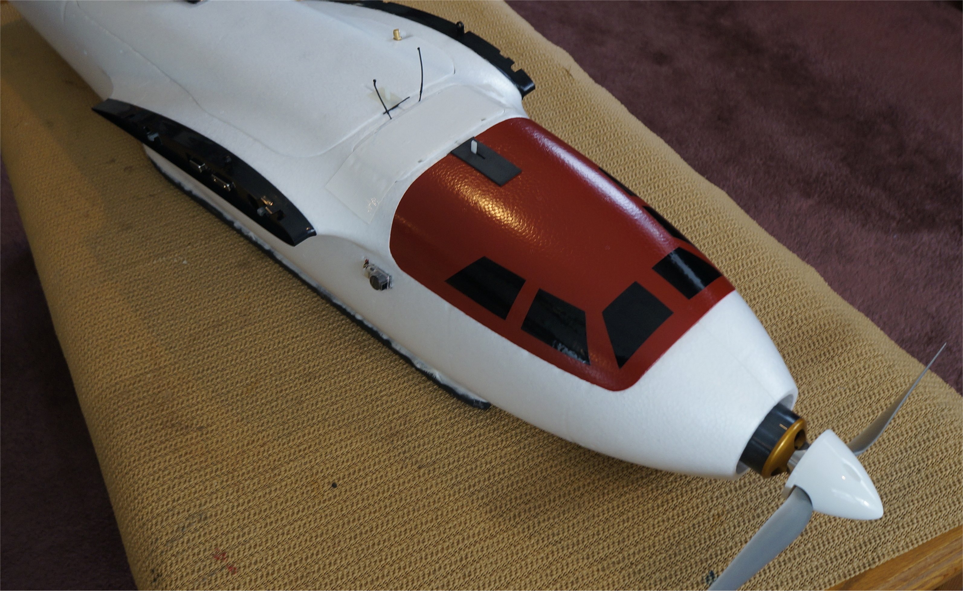
Since the weather turned bad, I decided to improve my battery canopy look with some Krylon Fusion Red Pepper spray paint and some hand-cut vinyl based off one of the MFE window decals. The hatch latch cover is sticky-back foam from Michael’s Craft store.