Hi Shawn,
Really appreciate your review and the very detailed suggestions. I must admit that I did not put enough effort to make the quad flies better. Following are my response :–

xfacta
      [Shawn](https://discuss.ardupilot.org/u/xfacta)


    December 18
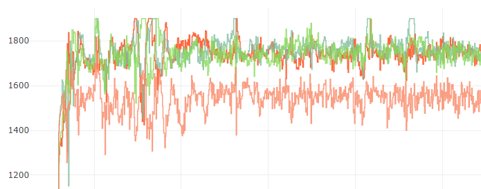
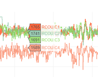
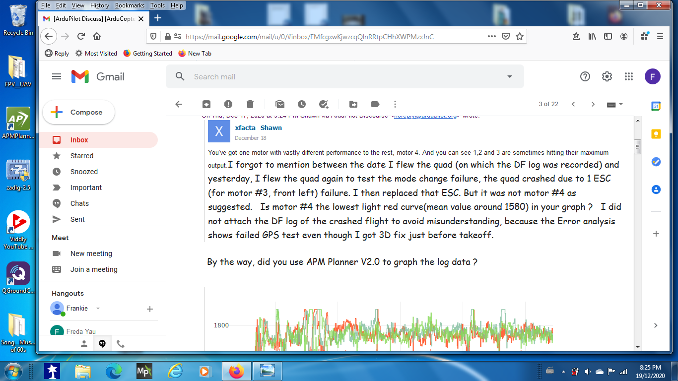
You’ve got one motor with vastly different performance to the rest, motor 4. And you can see 1,2 and 3 are sometimes hitting their maximum output.I forgot to mention between the date I flew the quad (on which the DF log was recorded) and yesterday, I flew the quad again to test the mode change failure, the quad crashed due to 1 ESC (for motor #3, front left) failure. I then replaced that ESC. But it was not motor #4 as suggested. Is motor #4 the lowest light red curve(mean value around 1580) in your graph ? I did not attach the DF log of the crashed flight to avoid misunderstanding, because the Error analysis shows failed GPS test even though I got 3D fix just before takeoff.
By the way, did you use APM Planner V2.0 to graph the log data ?
Reaching maximum output can be OK when it’s expected, like a moonshot or speed run, but you’re keeping a relatively constant altitude and inputting lots of attitude changes. Motor outputs should be centred more around 1500 to 1600 pwm typically.
So you aircraft is a bit overweight, and the battery voltage is not doing you any favours.I was thinking just a brief flight to check the mode change failure, so the pair of flight battery (30C) used was at storage voltage, 3.8v/cell without fully charged.
Maybe run the all-at-once ESC calibration and check the weight distribution.After I replaced the bad ESC, I did the all-at-once ESC calibration, and at the same time, happen to realize(after checking C of G) the pair of battery was placed a bit more towards the front after not flying for couple of months. This may explain the different performance of motor #4 (rear right). But why motor # 2 (rear left) not perform differently ? Since the C of G is shifted toward the front, should the 2 front motors work harder, or the 2 rear motors work less harder to maintain level attitude ?
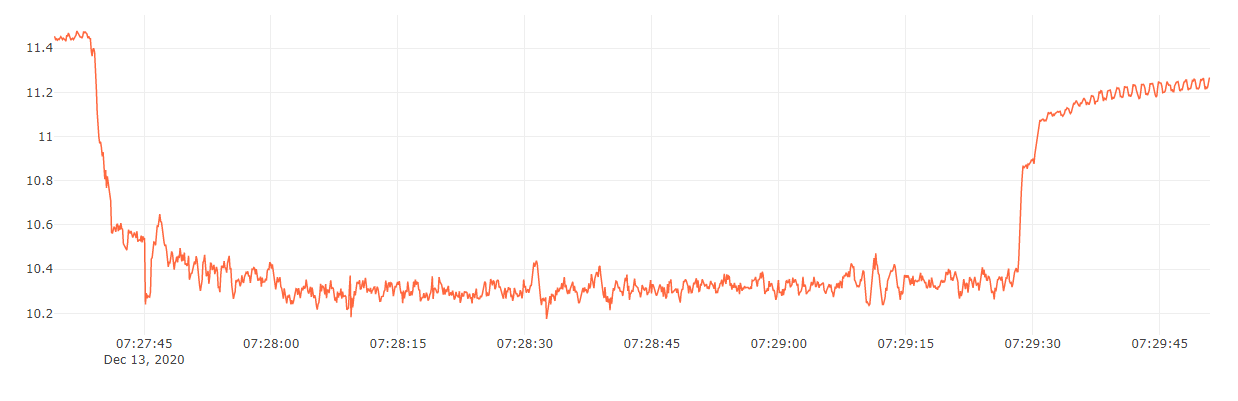
The battery voltage is low, like a very low C battery or it’s going bad. You can even see the oscillations at the end where the LED and beeper would have been going off after battery failsafe.
If you think the battery itself is OK and the voltage is good, then do the manual calibration of the voltage sensor. Calibrate at a low voltage where knowing the real value is most important.
Current monitoring is not working - it would be highly desirable to fix that.
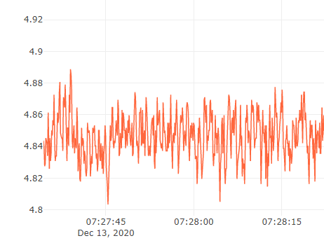
Vcc is a bit low, you might want to check or replace your power brick, or at least check connectors and measure the 5vdc input at the flight controller. Voltage at power module 5V output connector is 5.34V which inputs to Pixhawk power port.
Incidentally, I also measured the voltages at the BEC connector of ESC , and found out ESC #2 (rear left) has no voltage output. The other 3 BEC output ranges from 5.02 to 5.07 V. I think that BEC is dead. This does not matter, I think, as either 1 of the other 3 BEC supplies 5V to the output rail for powering the receiver thru the RC IN is OK. Pls confirm.
I’ve heard it said the the 5vdc is not very critical because most of the FC internals run off 3.3v anyway - BUT that 5vdc input is also redistributed to the GPS module and other external units too, such as RC receiver and telemetry radio. Add a couple of more connectors into the mix and the poor old GPS is expected to work off about 4vdc instead of 5vdc. Could you elaborate how and where I should add connectors in the circuit to raise the voltage for redistribution ?
If GPS is good while the FC is plugged into USB, measure the voltage to the GPS then and that’s what you’ll need as a minimum. Voltage at Pixhawk GPS port is measured at 4.84V after removing the GPS 6-pin connector.
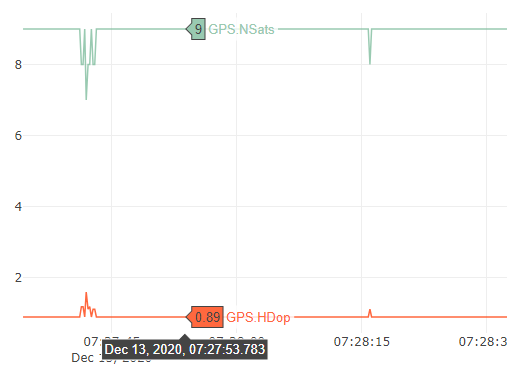
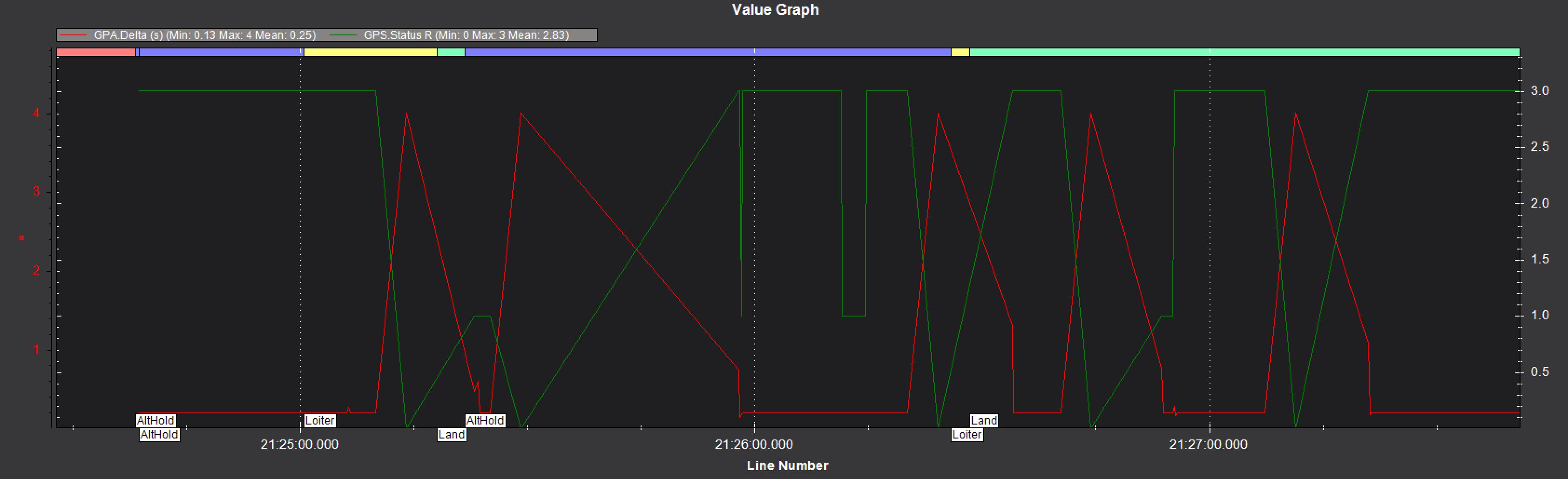
Number of Sats is only 9, and HDOP is not great - both are theoretically OK for providing a good 3D Fix but in reality you want better. Maybe fixing the Vcc might help. Probably try to measure the 5vdc at the GPS module and see what you get. Though the measured 4.84V at Pixhawk GPS port is lower than 5V, various online spec for uBlox NEO-6M says 2.7 to 3.3V, some say 5V. Anyway, this failure to change to loiter (Requires position)only happened recently without any hardware change, and I have been flying this quad with this hardware configuration for couple of years without problems.
Sometimes there are just bad GPS days too…I tried on 3-4 different days with same result.
I suggest you set these to help PID and thrust scaling with battery voltage, and the Fence will keep you disarmed until there is a 3D Fix and home can be properly set.Could you explain in detail about this ? I never configure Geofence before. You do stand around waiting for longer but it saves that panic and endless walking of a fly-away.
BATT_ARM_VOLT,11
BATT_CRT_VOLT,10.5
BATT_LOW_VOLT,10.8
MOT_BAT_VOLT_MAX,12.6
MOT_BAT_VOLT_MIN,9.9
BATT_FS_CRT_ACT,1
BATT_FS_LOW_ACT,2
FENCE_ACTION,3 — what will the quad do, RTL or Smart RTL or Land ?
FENCE_ALT_MAX,120
FENCE_ENABLE,1
FENCE_RADIUS,400
FENCE_TYPE,3
PSC_ACCZ_I,0.6
PSC_ACCZ_P,0.3
ATC_THR_MIX_MAN,0.5 — good suggestion
Check the altitude and radius to suit you local laws, or sanity 
Try this for smoother RC input. You can even go a bit higher, up to 0.3 to suit your taste.
ATC_INPUT_TC,0.2 Yes, medium of 0.15 was too crsip for me. I have set it to 0.3.
After all that, I’d run Autotune - the PIDs and many parameters are at defaults and pitch/roll tracking could be a little better. Will do Autotune after things are sort out.
While on the issue of P, I,and D, when I was able to change to loiter mode, the quad sometimes loiter in a relatively fix position which I am satisfied, but sometimes it drifts (no parameters changed before), probably under a light breeze. Could it be the accuracy of the GPS, or what parameters I have to set to make it loiter in a relative solid position like DJI models ?
Here’s a spreadsheet to derive starting values, or connect to MissionPlanner and press Alt A. What is the use of this spreadsheet ? I press Alt A after connecting the FC to MP, but nothing happens.

[Dropbox](https://www.dropbox.com/s/8u9v3ddph6u9u3t/Initial%20parameters.xls?dl=0)

Shared with Dropbox
And the tuning process instructions:
https://ardupilot.org/copter/docs/tuning-process-instructions.html
Thank you in advance for your marvellous assistance and expertise.
Frankie