Hi, apologies for my ignorance but I’m new to the Pixhawk and Ardupilot flight stack and I’ve not been able to find a clear explanation online thus far.
For a school project we currently have a Pixhawk4 running firmware version 3.6.11, airframe Quad X. We’re trying to set up a camera trigger and so far I’ve set the CAM_TRIGG_TYPE to Relay, and have tried setting the RELAY_PIN to every different option but never got a signal.
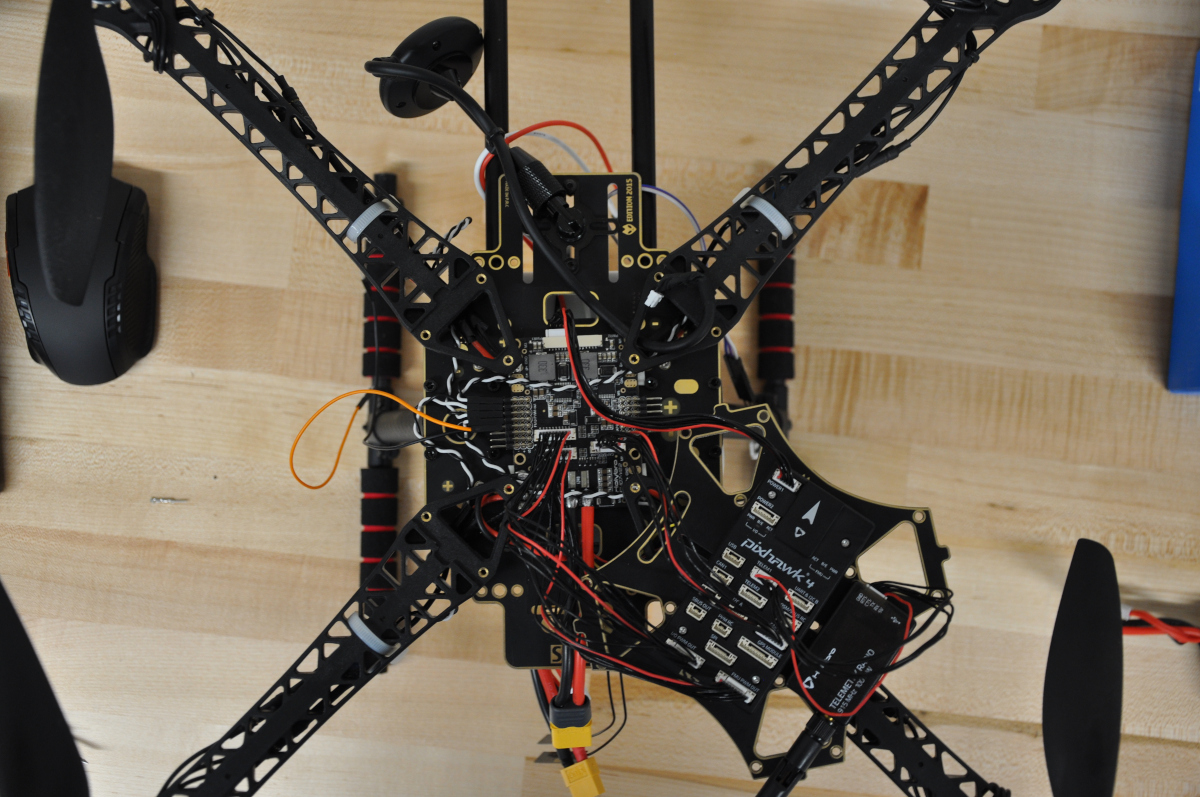
I think this may be related to how we have out Pixhawk connected to the power distribution board. The I/O PWM OUT from the Pixhawk is connected to the FMU PWM IN on the power board, and the FMU PWM OUT on the Pixhawk is connected to I/O PWM IN on the power board. We did this after finding out that the ESC signal cables were getting PWM info from the FMU-PWM-OUT pins of the power distro board.
I mention this because I switched the FMU and IO cables from the Pixhawk to power board and the camera trigger works but now out ESC’s don’t get a signal.
So I think this comes down to me not really understanding the FMU vs IO outputs/inputs. We had a very similar setup working with the camera trigger on an older Pixhawk, the one that had the Main and AUX out pins on the back, but with this new flight controller we’ve not been able to transition over very smoothly. Any guidance would be greatly appreciated.
Hi Jake, the part you describe, I figured that out. Let me try to describe and put you on the right track.
Consider this, Pixhawk 4, with the standard power board which comes in the box:
IO PWM OUT wired to the IO PWM IN on the power board
FMU PWM OUT wired to the FMU PWM IN on the power board
Arducopter configured for your frame, no further juggling around with servos, and RC.
In the above setup:
the PWM signals for your 4 ESC’s are available on the power board at the points M1 to M4. On the print itself, next to the respective main power for your esc’s. M5 - M8 are now not defined.
If you check the values of SERVO1_FUNCTION - SERVO4_FUNCTION, you will see they are mapped to your respective motors, as a result of your frame choice.
Now lets leave the other possibilities of the IO PWM OUT distribution for what its.
The FMU PWM OUT pins on the side of your power board can be addressed, by changing the respective settings of SERVO9_FUNCTION and upwards. 9 being pin 1 of the FMU PWM OUT pins on your power board. Just to figure out how this worked, I set SERVO9_FUNCTION to Rc_Passthrough value, which will follow your pwm on radio channel 9, configured a dial on my transmitter, hooked up a servo on this pin 1, and tadaa. Note that you need to provide your 5V and ground to those pins separately for servo, as they are not powered. Just use a separate bec (make sure same ground as pixhawk power board) and supply 5V to either one of the free middle pins of that pinstrip. Power pins are interconnected, so supplying it to 1 pin powers the whole strip.
I hope I have put you on the right track to figure your thing out. Took me a while to,get this sorted correctly. Too many people swap these cables for no reason. Pixhawk 4 also comes with 2 breakout boards for the respective IO and FMU PWM out. You can also opt for that if you do not want solder your esc inputs to the power board.