Yes, compass mot. I forgot that one.
Leonardthall, GREAT summary of the use of mAh, THX
one may wonder why there even could be a long debate about this in another thread
anyway, as regards precise mAh counting, you guys may have a look at the UC4H power brick, it measures current at a rate of 1kHz (could be increased if deemed relevant), so, this one does NOT miss to count current spikes 
(to the best of my knowledge, this is the only available (DIY) device which can do that)
I’d like to mention that filtering can improve mAh counting accuracy somewhat, but is not a substitute for fast current measurements, like the UC4H power brick does!
(this is simply because a filter is linear, while spikes and so on are not distributed symmetrically around the average)
In my experiments I got accuracies of 1-2 % without any calibration.
https://discuss.ardupilot.org/t/uavcan-for-hobbiests/16464/52
https://discuss.ardupilot.org/t/uavcan-for-hobbiests/16464/59
1 Like
That looks like a good sensor. However, the statement I quoted here is incorrect. It is actually much more correct to say “High sample rate is no substitute for appropriate filtering”.
If you low pass filter correctly you will get just as accurate current average as you would with a lower filter and higher sample rate. It is just easier to implement the filter if you can use a higher cut off frequency.
By definition the area under the input and output of a linear time-invariant causal filter is the same assuming unity gain. So when you are integrating the filter response to measure mAh a low frequency filter and a low sample rate will be equally accurate as a high frequency filter with a high sample rate.
1 Like
I disagree with that
a causal filter is not an integrator (except in specific cases)
and “summing digital samples” is not the same as mathematical integration (in continuous time, which is what we need for for accurate mAh counting)

I should add: the reasoning depends on the type of ADC, I’m of course talking about ADCs like that in the STM32
to put the discussion on more solid feet, here a sketch of the two methods under discussion
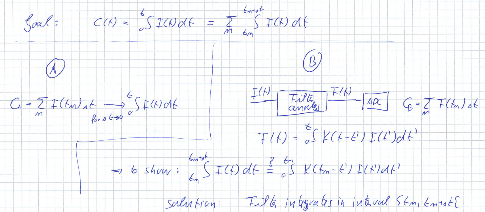
since you’re saying that it is possible you should be able to give me an explicit filter which is a solution to the “to show” condition, which is not an integrator.
EDIT: sorry, the integral boundaries for the current integrals should obviously be t_n and t_n - \Delta t, not t_n + \Delta t and t_n.
I never said a filter was an integrator. I said that all you have done is increased the sample rate.
(I was referring to the filter response of the current output)
Sorry but I have no idea what you are trying to say with the filter side (B) of your diagram there. I suspect that is because you think I am saying the low pass filter is an integrator.
So maybe I can give an example to make this clear. I understand that your board is directly measuring current from the hall effect sensor then performing digital integration as shown by (A). (I assume you are not running an analogue integrator then resetting it after each measurement and measuring total-current separately to current. You seem to describe this at the top of your page.)
Arducopter does (A) but at 10Hz. I understand that your board does (A) but at 1kHz.
So let’s look at the response of (A) to an ideal impulse. Lets define the ideal impulse has zero length and infinite magnitude with an integral of 1 then your time tm will probably never catch it and if it does it will read infinity. So a direct digital integration will measure zero or infinity, this is true no matter how fast you sample. If you lowpass the impulse before you sample it the integral will still be 1 but you will measure a finite current over a finite time. Provided your sample rate is significantly greater than the low pass filter cutoff you will be able to accurately integrate this digitally.
So are you saying that you are doing something other than sampling the current and performing digital integration?
If you are doing simple digital integration of a current measurement then you are doing exactly the same thing the pixhawk is doing but at a higher rate. The rest is just appropriate filtering and the response time of the measurement.
If you are running an analog integrator that you are sampling and resetting then yes, this should catch any impulse and result in an accurate mAh measurement.
So what method are you using?
???
I did not say nor indicate that I think that you’re saying that a filter is an integrator … exactly to the opposite: you’re saying that even if it is not an integrator it will do the job, while I’m telling that in order to do the job it must be an integrator.
I’m doing (A). You are suggesting (B). I think the drawing is pretty clear; not sure what it needs long questioning text.
I perfectly understand what you’re trying to say with " the area under the input and output of a linear time-invariant causal filter is the same assuming unity gain", but you overlook that this is true only for a mathematical continuous time integral and not a digital integral, and in addition that all transients must have been integrated and that it is thus not true at any point in time. You can easily convince yourself of this by looking at the output of a 1.st order LPF subject to a switch-on and switch-off.
ok, so all this is just a waist of text then as you are just stating the obvious for no reason.
Neither of us is doing continuous time integration.
So you are just doing direct sampling of the output with no filtering. I am suggesting filtering before sampling.
No I did not overlook this.
What does that mean?
Are you honestly telling me that you think the digital integration is more accurate without input filtering. This is so fundamentally wrong I struggle to find the words to respond. Just look up aliasing for example:
And you didn’t even consider my impulse example.
I am starting to get the feeling you are turning a blind eye to basic signal processing to justify saying
Both statements are false on the time scales we need to make these measurements.
seriously, LOL
the only thing what I’m saying is that in order to approximate an integral one needs to go to small steps, and the shorter the steps the better the approximation, and that there is no way to approximate the integral in general by keeping large steps.
it doesn’t appear you are giving any thoughts to what I’ve said
obviously one needs to draw simple plots to see the obvious
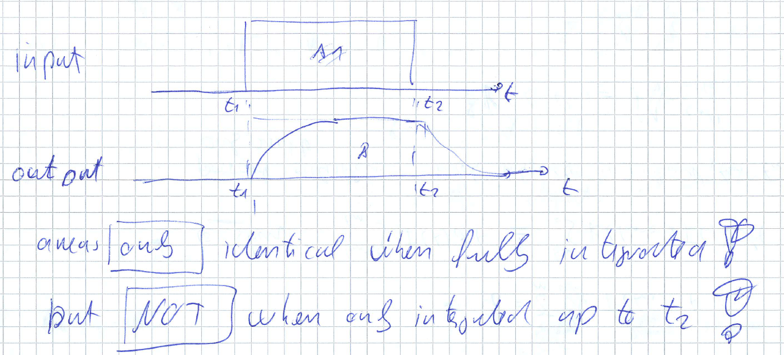
ergo: “the area under the input and output of a linear time-invariant causal filter is the same assuming unity gain” is incorrect. Q.E.D.
you are free now to draw in your sampling points yourself to see that this wouldn’t be the integral. Q.E.D.
one needs exactly zero knowledge on whatever but just common sense to see that.
also, you totally disgres from the point of discussion.
The point of discussion was your statement that with proper filtering one could also get equally good results with a slow sampling rate than with a (much) faster sampling rate.
I only can assume now you disgress on purpose, since I obviously was quite willing to be serious.
So I used matlab to simulate a second square pulse with a magnitude of 1 and I then pass that signal through a first order low pass butterworth filter with a cut off frequency of 1Hz. I then use matlab to calculate the area under each graph.
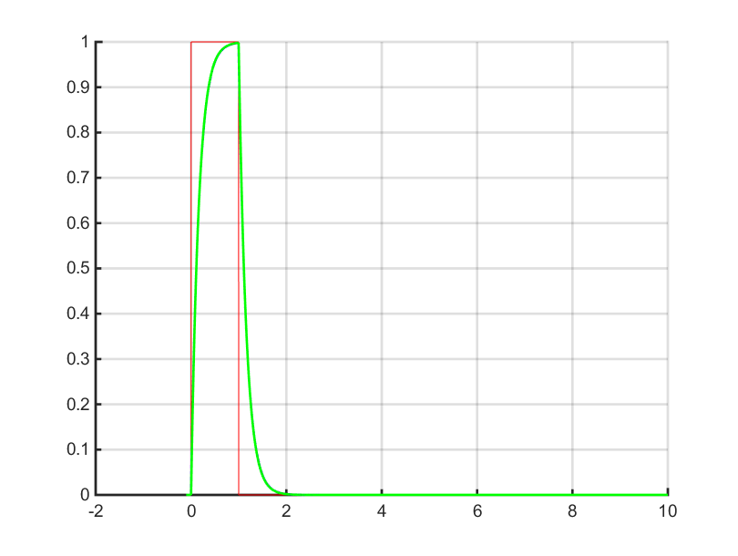
Here is the output:
LowPassFilter
Fcut: 1 RC: 0.15915 Alpha: 0.015465
Area of input : 1.00000e+00
Area of output : 1.00000e+00
Now I realise this isn’t a hand draw diagram so the accuracy may be a little different to yours.
For interest sake, with a filter frequency of 0.1 Hz where I don’t integrate for long enough:
LowPassFilter
Fcut: 0.1 RC: 1.5915 Alpha: 0.0015683
Area of input : 1.00000e+00
Area of output : 9.97401e-01

Well, sometimes zero knowledge and common sense don’t give you the correct answer. That is where engineering comes in.
So let’s see… We have seen this sampled at 400 Hz… what about 4 hz
LowPassFilter
Fcut: 0.1 RC: 1.5915 Alpha: 0.0015683
Area of input : 1.00000e+00
Area of output : 9.97401e-01
Area of output and 1/100 sample rate : 9.97442e-01
I look forward to a serous response to my matlab results.
1 Like
No “serious” response yet I see.
I thought I would add a little simulation result here. I produce a short pulse through a 1kHz direct sampled system as you propose and compared it to a 10 Hz system I proposed and for interest showed a 1kHz system with appropriate filtering.
Area of input : 1.00000e+00
Area of input and 1 kHz sample rate : 5.29101e-01
Area of output and 10 Hz sample rate : 7.63648e-01 (1 Hz filter 1st order)
Area of output and 10 Hz sample rate : 9.81965e-01 (1 Hz filter 2nd order)
Area of output and 1 kHz sample rate : 1.00124e+00 (100 Hz filter 1st order)
As is clear to see the filtering is much easier to implement with a higher sample rate and it is easier to achieve a much more accurate result. So as I have tried to explain numerous times, the higher sample rate makes it easier to achieve accurate measurements but does not result in an accurate measurement without appropriate filtering. The reason it is easier is because the filter cutoff frequency can be set higher.
The other thing worth pointing out for people reading. I am showing a worst case example here. The normal input to the current sensor is not a single short pulse it is dominated by a constant current as it is being filtered by the capacitors on the ESC’s and inductance of the wires. So don’t take these numbers as the absolute current measurement accuracy.
So a quick reminder of the statement that started this discussion…
Most of the Allegro current sensors have a FILTER pin. A capacitor to GND added there produces a first-order filter in the analog domain. The output impedance of the Allegro is low enough that you can add another R/C network on the output to give you a 2nd order filter with no software overhead.
Also, I added a parameter in the code called “_batesr” It defaults to 0.025 milliohms, but can be changed. 0.025 ohms is the approximate ESR of most 4-cell batteries.
The code takes the low-pass filtered current from the current sensor and multiplies it by the ESR and adds that to the measured battery voltage. The result is MUCH more accurate indicator of real battery voltage.
Do you have links for the filter pin so I can see where to do it?
And what code base are you referring to when you talk about your ESR?
The ACS713 family (up to 50A) use pin 6 as the FILTER pin. The larger ones (up to 200A) don’t have this pin. For those, you can put two cascaded L/C filters on the output pin if you want a second-order filter.
And as far as the code base - I’m still in APM 3.2.1 land. I have never been able to compile PixHawk code. So I have been making incremental improvements to 3.2.1 on my own.
Yeh, on my own boards using the 200A sensors I put an output filter on there. I thought you were saying the Mauch sensors had a designed in filter pad or something.
Well done on improving the 3.2.1 code. It may be interesting to you to see how we are learning the internal impedance of the battery from the readings. It works really well!!
Yes, I first thought of taking the voltage and current readings and storing them in short circular buffers, and the first time the current changed more than 25A over a period of less than 5 sec, I would measure the voltage before and after the current step and automatically calculate the ESR from that. But for the time being, I just manually insert the value. For a relatively new 4 cell, I find that 25 milliohms is a good value, which I use as a default. But like I mentioned, that value can be changed as a parameter in Mission Planner.
With my method, the measured battery voltage does not dip during hard climbs and there are no “steps” in the voltage readings - only changes in slope as the current draw increases and decreases. This is a vast improvement over the original code.
I made another, similar change to 3.2.1. It lets you enter the number of cells as a parameter. The code then looks at the PERCENTAGE REMAINING and if it is above 80(%), then the battery voltage should be greater than (num_cells * 3.8), if the percentage remaining is above 60%, the battery voltage should be greater than (num_cells * 3.5), if he percentage remaining is above 40% the battery voltage should be greater than (num_cells * 3.3). If any condition is violated, a battery failsafe is issued.
This solves two problems: When the battery is first connected, the percentage remaining is set to 100%. But if the battery is partially discharged when you first connect, you could be fooled into thinking you have more battery than you realize and send the craft on a long mission (and it would not make it home).
The other problem is if the battery has diminished capacity (or someone puts a smaller battery on the craft than has been entered as a parameter). In that case, the battery runs down too soon and again, might not make it home on a long mission. My code change solves both problems.
Nice!!
And I can confirm what you said about having the ESR dramatically improving the resting voltage calculation and being much nicer to work with than the measured voltage. As you say, large currents don’t cause the resting voltage to drop imiediatly. I do see the “sag” in resting voltage as the battery can’t supply those large currents for an extended time and the battery voltage sags below Current*ESR.
Nice work!!
Thank you!
It has been much harder than it should be because absolutely NO ONE answers me when I ask code questions about 3.2.1
I’m writing my own object avoidance routines (radar and LIDAR) in a TEENSY 3.2 and handle control, telemetry and live video over 4G using a Raspberry pi. I know I must be duplicating someone else’s work, but since no one answers my “silly” questions, I don’t know.
I realize that the focus is not on that old version, but it bothers me that no one can take even one minute to answer a question that they probably know the answer to. I’m a very good hardware engineer and have written programs with over 15,000 lines using PicBasic Pro (PBP). PBP is much closer to assembly than Arduino C++.
I could contribute an awful lot if I could be part of the “in crowd” and be taken seriously.
I understand the frustration Charles,
The challenge is that we are so stretched for time that we have to focus on support and taking the project forward. It is extremely difficult to look back that far at the code because we have to work out all the things that we have not fixed and done at that point in time. And to be honest it is also really frustrating to deal with all those old issues that we worked so hard to fix.
To flip this over. You said that you are working on 3.2.1 because:
I am sure we would be much happier to take one minute to help you get the code compiling for PixHawk. You can imagine that it is equally frustrating to us that you decided not to make the effort to learn to compile on PixHawk so you can contribute to the latest code base and therefore make our time helping you help us.
This is not supposed to be confrontational or even a criticism. I simply wanted to try to explain why you may not get the level of support you wish you got.
I understand. I would be very, very happy to learn how to compile
PixHawk fw. I HAVE tried several times with no success. After a week of
frustration, and no help, I realized that I would be forced to work on
the code I COULD compile.
I’ll try again.
Charles Linquist
Check out my multirotor blog at http://calmultirotor.com
1 Like