I have to adress a issue concerning the voltage calculation. Seems that i have unusual voltage drop with throttle higher then 50% but in real measuring with voltagemeter no voltage drop is noticable.
Example for 4s lipo
Log 10 Volt
Voltagemeter 14.8 Volt
I have found that the voltage/current measuring works extremely well, i get better than 99% accuracy compared to my reference multimeter. So your isssues might be related to your specific config…
What power module are you using?
Have you calibrated your power sensor using your GCS (e.g. missionPlanner) as explained in the documentation?
What current are you measuring, i.e. how big is the load on the batterie? And what capacity does your battery have?
And when you measure the voltage of 14.8V with the voltagemeter - what throttle % was that measured at?
A measurable voltage drop is normal between an idle battery and a battery under significant load - even though 4.8V feels too much for a 4S battery.
Could be many things from incorrect calibration, battery overload, defective power module etc. I suspect the first, but hard to tell without specifics.
It could be a lot of things. You need to provide more info.
1)data flash log
2)battery size type ect.
3)what power module you are using
4)motor size and type of copter(how many motors)
If I had to guess either there is a calibration issue or the battery is too small for the load required. I can’t tell without the information listed.
Well this is a Hexacopter F550 for acrobatic purpose. On full throttle it make about 23m/s climbrate.
The Current is measured with 180 Amps. The Lipos i’m using are the SLS Magnum 4000 4S 45/80C this are for professional use and in my opinion the best on the market.
As Powermodul i’m using a Attopilot 180Amps which i have calibrated with Mission planner. Basically it’s measuring the correct voltage until throttle is going over 50%. If i make the calibration on 75% throttle i get 17.8V on 0% throttle. So the difference is always about 1-1.2Voltage.
if nobody of you have this issue it is likely possible that the problem could be the Powermodul ? i have modified the Attopilot and added a Voltage converter to get the 5V i use for Pixhawk (only) this could perhaps do the issue ?
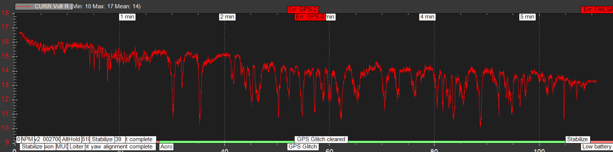
As you see on the Image the are peaks going to 10 Volts but this is adressed to a wrong measurement. The voltmeter stay to about 14.8Volt all the time.
VoltR is an estimate of the batteries resting voltage, which is taking into account the current draw on the battery, and is a filtered value, not the instantaneous actual voltage. If you want that graph CURR.Volt (called BAT.Volt in 3.6). Depending upon your battery setup this can preform quite badly (it’s not a feature I use, as it is invariably wrong for my plane usage)
what makes you think that failsafe is kicking in too early?
If I look at your graph of curr.volt it appears to be a “normal” discharge curve, leading you from 16.8V (full battery) to ~14V at the end, at which point the battery failsafe kicks in (as it probably should, 3.5V per cell of failsafe level is what many people use as default I think).
What is noticeable are the momentary negative spikes that get close to 10V (I assume these are max load moments). As far as I know 2.5V per cell is the threshold that must not be gone below as at that voltage the cells take unrecoverable damage.
To me this looks as if you are pushing your battery to the limit with the max current you mention (180A is 45C for a 4Ah battery…).
You might want to consider getting a slightly bigger battery with the same C rating, that should help have less dramatic voltage drops (and let you fly longer at the same time).
How much mAh do you get charged back into your battery after such a flight that terminates with failsafe?
Chris
P.S. I would definitively do the voltage calibration with 0% load - 16.8V sounds perfect as idle voltage for a 4S battery.
The answer is “it depends.” If you provide your flight log, I would be able to tell you what is happening exactly.
The possibilities are:
Failsafe is triggering on mAh consumed (BATT_LOW_MAH or BATT_CRT_MAH > 0)
Failsafe is triggering on corrected voltage (BATT_LOW_VOLT or BATT_CRT_VOLT is > 0 and BATT_FS_VOLTSRC = 1 and the voltage dropped below this threshold for longer than BATT_LOW_TIMER seconds.)
Failsafe is triggering on raw voltage (same as above, but BATT_FS_VOLTSRC = 0)
BATT_LOW_TIMER is there to prevent the failsafe from activating during high-load maneuvers. But, looking at the graph you posted, I do not think this is the problem, as the failsafe did not trigger during any of the voltage sag events. The failsafe appears to be working as intended.
Regarding the excessive voltage sag, you say that you measured battery voltage with a voltmeter during high load, and the voltmeter showed much higher voltage than shown the Pixhawk log? May I ask how you performed this test?
If this is true, then there is resistance in the power circuit somewhere between the voltmeter probes and the power module, or the power module voltage scaling is wrong.
i only setup the FS_BATT_VOLTAGE at 14 Volt and i suppose that as you wrote the BATT_LOW_Timer is shooting the Failsafe after 10 seconds. It has to be as nothing else is setup.
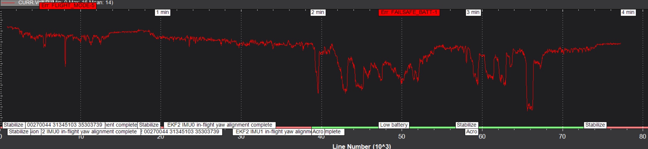
The diagramm i posted was from a new battery with about 4 cycles so this works well but its getting worse with older batteries. I have older Batteries with 30 cycles which are shooting in failsafe after 1-2 Minutes. See below graph from older Battery with about 30 cycles on it. (Ok its a 35/70C so its really pushed to its limits)
How does the BATT_LOW_Timer works, is it counting the time the battery Voltage is below FS_BATT ? If so then looking on the Graph below this is probably kicking in. As wrote before this is caused by a bad Voltage log. I’ve done a lot of testing and the Voltage is not falling some much for real.
The voltage sag problem either lies with the battery or with the electronics/wiring. To know which, we must be sure that your measurements are correct. That is why I am asking for a description of how you measured it.
Voltage sag while under load is normal, so when you say that the battery was constantly at 14.8V when you measured it makes me wonder how you performed this measurement. You must make the measurement when the drone is drawing 100+ amps. You must also make this measurement at the battery and at the ESC to be able to tell where the sag is coming from.
Its simple i rotated the props one motor clockwise so it will not take off but push itself into the ground.
(Same for doing the motor/compass calibration) then i attached the Voltmeter to the Battery connector and compared in realtime to the Voltage output in Mission planner.
I don’t know about the resistor, i added a Volt converter to the Attopilot PM to provide the 5 Volt which is use to power up the Pixhawk. something like this i googled on the fly probaly this are other sepcs of mine :
Perfect. But just to make sure: did you rotate the props AND flip them upside down? If you only rotated them, they will be spinning backwards and won’t load the motors very much and the voltage will stay pretty constant.
I recommend running this same test again, but now put the voltmeter probes to measure the voltage coming out of the power module. This is to make sure that there is no extra resistance that is causing real voltage sag.
If there is no excessive sag, then yes it is probably a calibration issue. I have never used the Attopilot so I’m not sure how accurate it is, but I think there is a setting for it in Mission Planner. You could try that instead of trying to set the scaling manually to see if that helps.
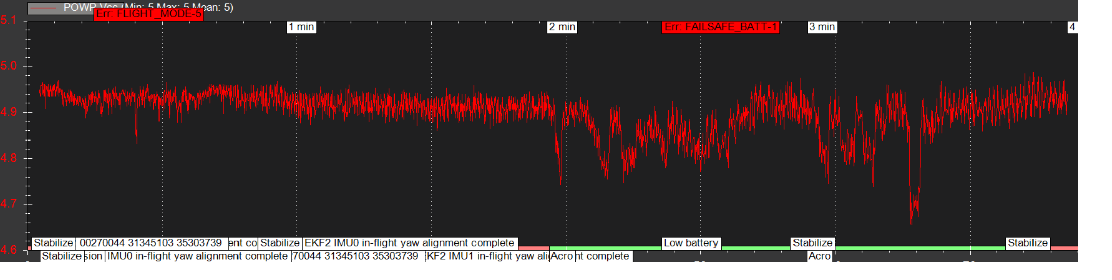
The 5V Pixhawk supply shouldn’t cause any issues with voltage sensing, but you can ensure that it is working properly by checking the PWR.Vcc field in the logs. This is the Pixhawk board voltage.
On top of all the tips related to configuring failsafe etc. - have you considered that your multimeter might be the “issue” here? Just thinking that I can hardly imagine the voltage stays “constant” at 14.8V if you apply peak loads of 180A on a 4Ah battery… Maybe your voltmeter does long timeperiod averaging and thus you are not able to see the voltage drops on the multimeter but the pixhawk picks them up and shows them nicely in the log as we can see from the pics… just came across this thought…
No the multimeter is showing real time voltage i’m sure. it would be interesting to test the voltage on the output of powermodul as mentioned by anubis. But its no so simple as i sealed the solder joints.
@Pomaroli please just post the raw log, or post a graph of CURR.Volt. I think you will find that looks much more like your multimeter, but without that this thread is just aimless speculation.