here is the log https://www.dropbox.com/s/u4r65n5vy32q5ft/2018-04-08%2017-35-52.bin?dl=0
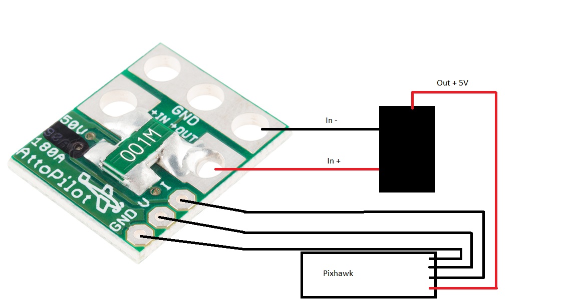
Voltmeter is connected to the main leads, connector is XT90 with AWG10 cable.
The Pixhawk Power Port is specified with 5 Volts, i didn’t notice any disadvange so far.
Based on the logs I see only a couple possible causes.
- You have an increased resistance somewhere the system, which which draws power. However it is very unlikely, since that amount of power would cause melting, charring and smoking… unless it is at the power connector, check the temperature of the XT90 pins right after disconnecting.
- Your power wires are too thin. For 150A you will need at least AWG12 cables all the way to the power distribution panel. And a PD which is rated for such current.
- You battery is shoot. (Assuming it is not the case, if your measurements are correct.)
@Pomaroli I apologize, the battery resistance estimation stuff never made it into Copter 3.5 and I thought it was. In that case you really are seeing what the autopilot thought the battery voltage was.
The only thing I can point to at that point is that I’ve had issues in the past with ground lifts that were induced by the load of a RFD900 radio (at 1W) on the autopilot power supply, or a bad ground reference.
In your diagram you have Vin- tied to gnd on the attopilot, if Vout- isn’t identical to Vin- you will have issues, and it should be tied together. (If your regulator can’t support this then you have a ground loop issue here).
Andras AWG12 is smaller then AWG10 or i’m wrong ? The battery has AWG10 and it remains AWG10 until distribution board. The connector are not getting hot, nor the Brushless controller. The motors a little bit warm when pushed hard.
Ok. So cables and connectors are good.
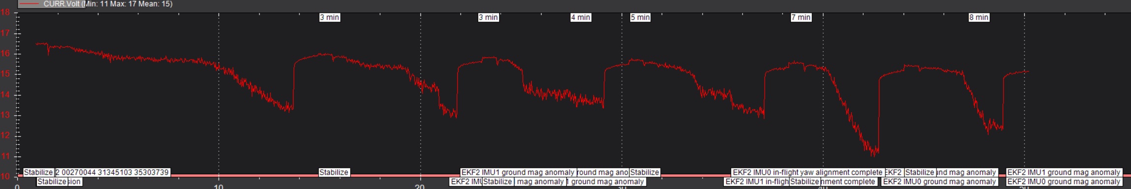
I found something interesting:
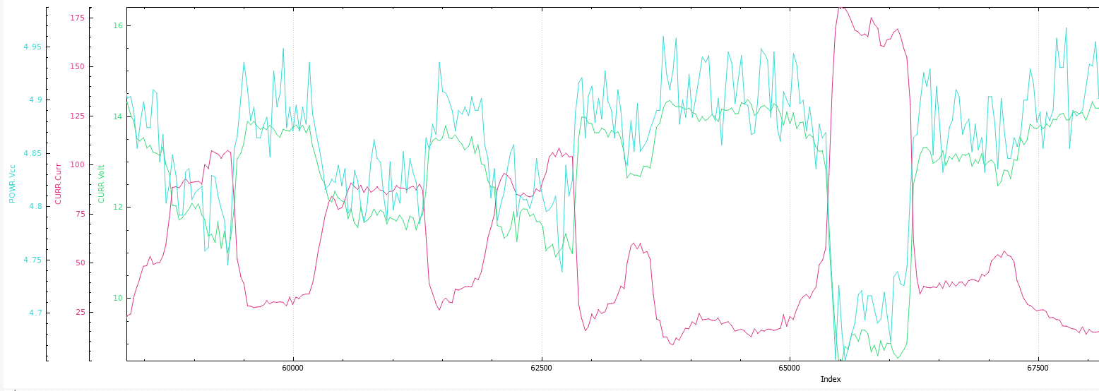
VCC and Batt.Voltage swags together and linked to current.
WickedShell you mean that Vout- should go to the pixhawk and not GND ? This is also what i was thinking about but i don’t have any issue so far a part of this “wrong” measurment. I can try this but to do so i need to remove the seal from the Volt converter. I seal allways all joints with liquid plastic.
An exact type of the converter could be helpful as well. 
yes this is interesting but how is VCC measured ? or is it calcuated value ?
It is measured, so perhaps it is indeed a problem with the ground reference…
My comment was based on the 4 pin package you linked above. Depending upon the type of regulator that is, Vin- and Vout- can have a (changing) voltage differential between them, and trusting that they don’t can lead to a variety of power/ADC issues like this.
so it was some years i go i’ve build the PM but now i have found the Information about it in my notes
Its a DC to DC converter Recom type R-78B5.0-1.5, probably it has only 3 pins.
Mistery deepens, the recom indeed has only three pins and a common ground. Now I’m baffled…
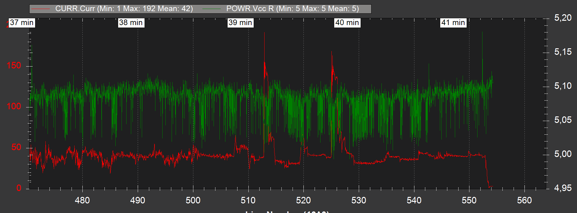
Also a fluctuating Vcc (+5vdc) will affect the voltage and current readings (as I found out elsewhere) so you really need to stabilise that Vcc and make it extremely reliable or your other measurements will be wrong.
It seems like problems are being compounded - large current draws are affecting your Vcc, which in turn affects your Vbat reading, and so on…
I reiterate what others have said, the Vcc is too low at an average of 4.95 and dips to 4.7 - it needs to be at least 5.2 minimum and not show any signs of dips due to current draw at the battery.
Take a look at the Mauch power modules. He has a model that is designed for high amp installations up to 200 amps.
http://ardupilot.org/copter/docs/common-mauch-power-modules.html
The Mauch Pm seems to be fine, but needs a external bec correct ?
i guess there should be also DC to DC converter with Volt stabilsation, i will search lets see.
Yes, Mauch also has a variety of BECs in offer - I have used the very simple ones (1 voltage) as well as the more sophisticaed multi-voltage versions. All of them are very solid - I have not had any issues since I use them, and the voltage is very very stable - maximum voltage sag is <0,1V, even under maximum load conditions of 190+A.
So i’ve just finished with the rework on the PM, i’ve replaced the DC to DC converter with a common 5V BEC.
The soldering is done exactly like it is described on the Docs for the Attopilot.
So far everthing is booting up fine, will test tomorrow if there is still a significant change in voltage or if its gone.
So guys no change, same behavior also with a 5V Bec. The problem wasn’t the DC to DC Converter.
Starting from mid throttle the calculated Voltage seems to be wrong, the voltmeter showing stable 14.2V while the Software is showing 11V. I measured with the Voltmeter before and after the Attopilot it’s the same.
Is there anybody using the same Attopilot PM with the same behaviour ? or any idear’s ?
otherwise i guess i have to life with it, knowing the battery is ok. For the next copter which is in planing i guess i will use the Mauch and a pixhawk mini.