Does anyone use the DragonLink telemetry?

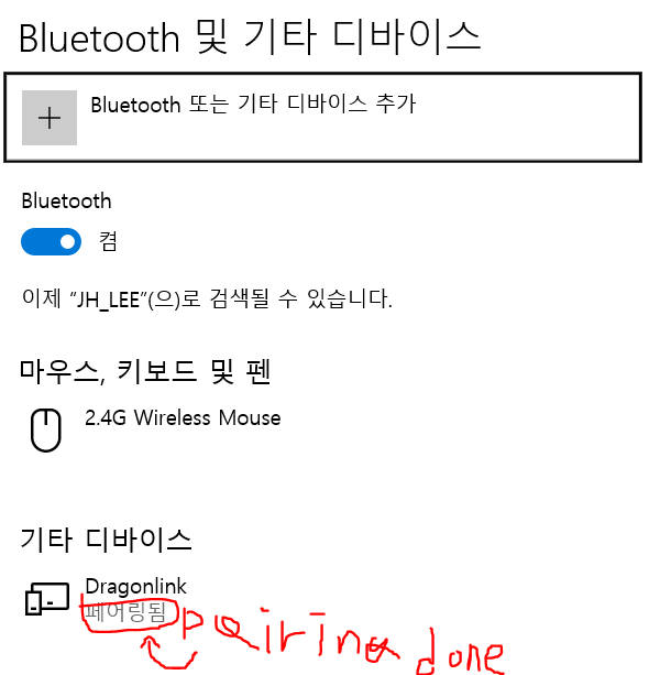
I have confirmed that there is a telemetry feature of Dragon Link.
I would like to use the Dragon Link as a telemetry.

First of all, I refer to this link.

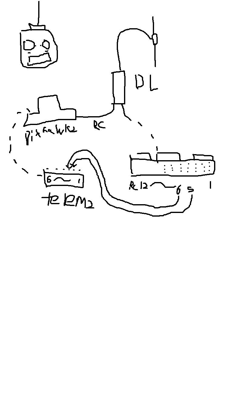
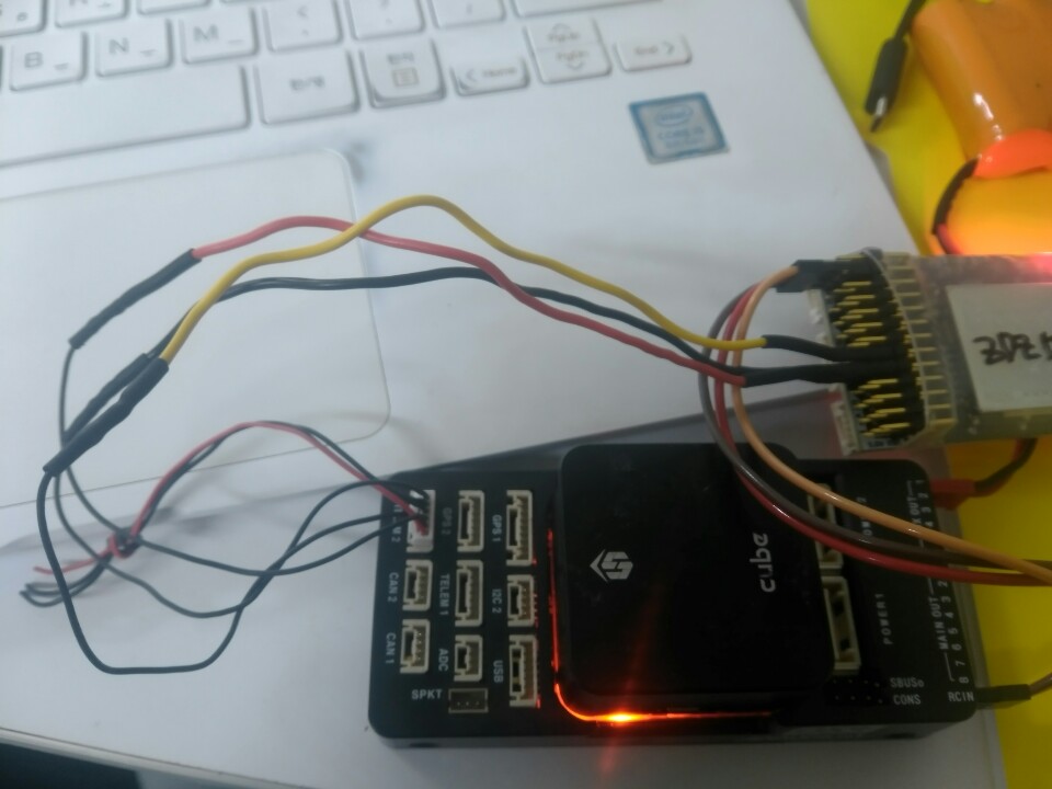
I tried to run it like this.
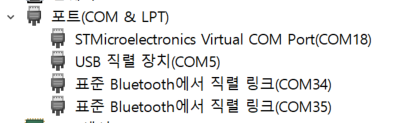
I have picked up the port to connect to in Mission Planner, but pressing the Connect button will freeze the mission planner.

I wonder if there is any part that I am missing.

Or if you are already in use

I hope you can help me.


I am really grateful to you for always helping me.

generally, there’s two options for mavlink telemetry via DragonLink:

1.: unidirectional mavlink telemetry downlink encoded in your bidirectional RC link.

2.: full bidirectional mavlink telemetry via DL’s radio modem feature.

a plentitude of information and instructions can be found on the dragonlink homepage, additional support is provided on RCG’s massive dragonlink thread: https://www.rcgroups.com/forums/showthread.php?1518533-NEW-DRAGON-LINK-ADVANCED-Full-Telemetry-Bluetooth-Droid-Planner-Data-Modem

to setup a full bidirectional telemetry link via DL radio modem feature, best use the latest DL firmware:
http://www.dragonlinkrc.com/instructions/v3equipment/v3completesystem/

in contrast to previous firmwares it offers additional high data rate settings that allow a full bidirectional telemetry link at ardupilot’s default of 57.6 kbaud. depending on your actual receiver hardware, there’s support for optional flow control too (fullsize RX only).

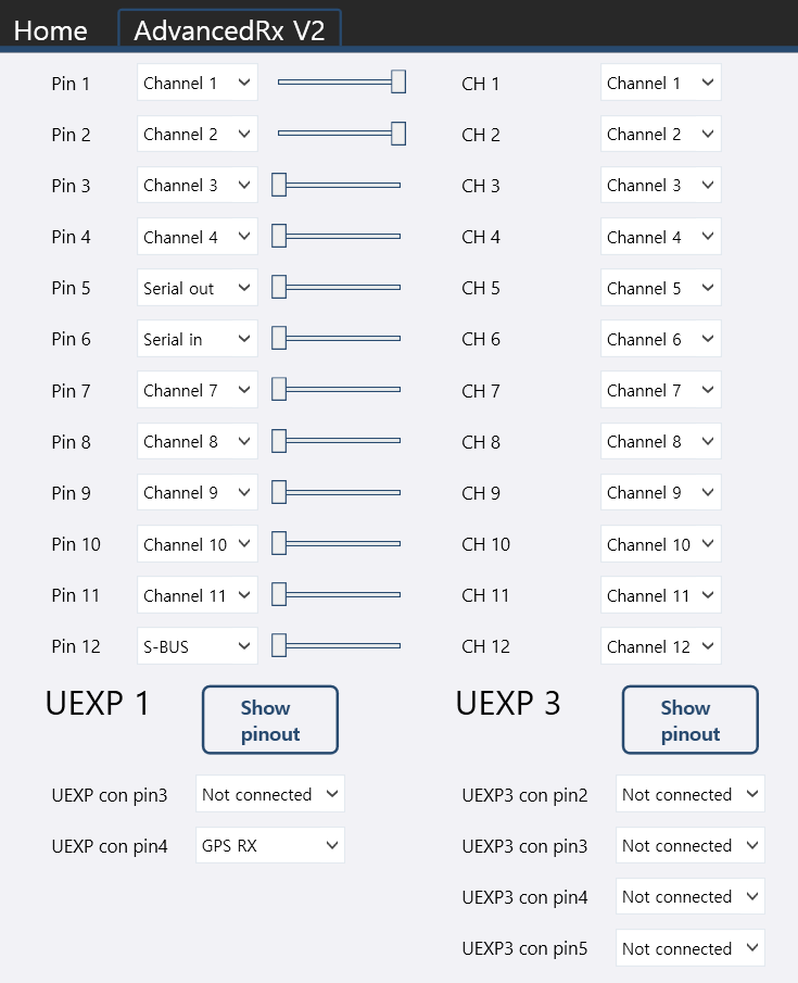
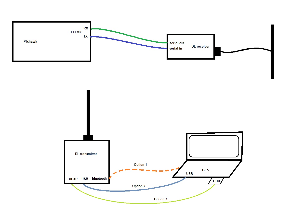
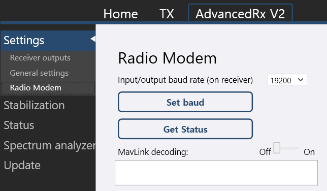
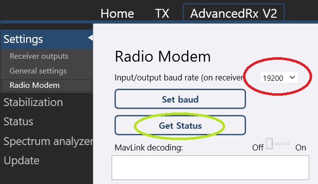
with your DL RX connected to the DL GUI, define two physical pins as serial in (=RX) and serial out (=TX). connect these accordingly to your pixhawk’s telemetry port’s TX / RX pins (RX->TX and vice versa). set the radio modem’s baudrate to match your pixhawk’s serial port’s baudrate. default ist 57.6 kbaud.

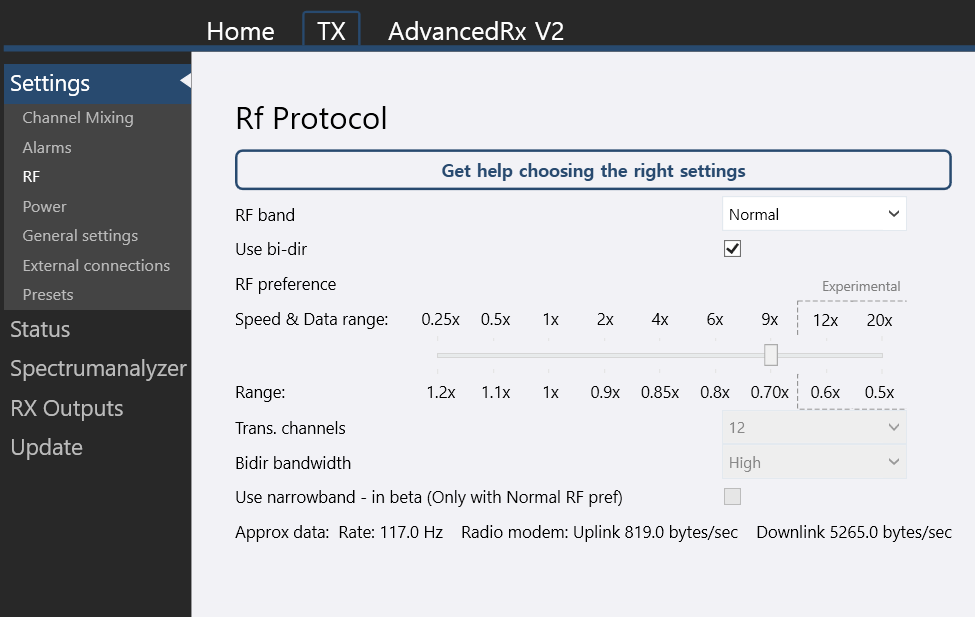
on your TX connected to the DL GUI, adjust RF settings to provide a high enough data rate for your respective baudrate settings. for a default 57.6 kbaud link you’ll need to set “speed & data range” to 9x, offering ~5250 b/s at reasonable range loss. don’t forget to rebind your receciver whenever you change your RF settings.

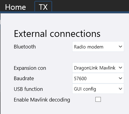
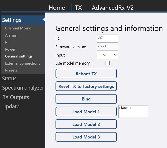
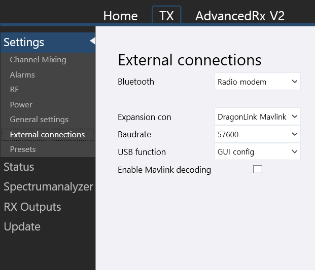
now set the baudrate on your DL TX accordingly and choose the external connection to use for your DL radio modem <-> GCS link. it might be prefereable to first use a wired connection for testing, as it helps to rule out bluetooth connectivity issues while setting things up. once you can connect to your GCS and get telemetry via DragonLink, you can set “bluetooth” as your external connection and proceed with testing.

cheers, basti.

Hello vierfuffzig

Thank you very much for your reply.

I would like to use the DL’s telemetry function the same as the telemetry function I used so far.

This is equivalent to item 2 you mentioned.

I read your article and have a question.

The TX portion of the DL (black square, connected to the controller) is connected to the computer.

I think RX -> TX, TX -> GCS information is transmitted in this way.

When I get information from TX-> GCS, I think I use Bluetooth communication to pass information.

I think i need a wire when you mention it.

My TX only has USB and UEXP ports.

Which port should I use …?

If it is connected to the computer via wire, is it connected to the usb port of the computer?

What exactly are the physical RX and TX parts of the DL you are talking about?
Is the setting UEXP3 in RX GUI?
What is the UEXP3 port in this picture?


%EC%BA%A1%EC%B2%98999

In other explanations, I connect to the TELEM2 port, but what is the TELEM port you are talking about? 2?

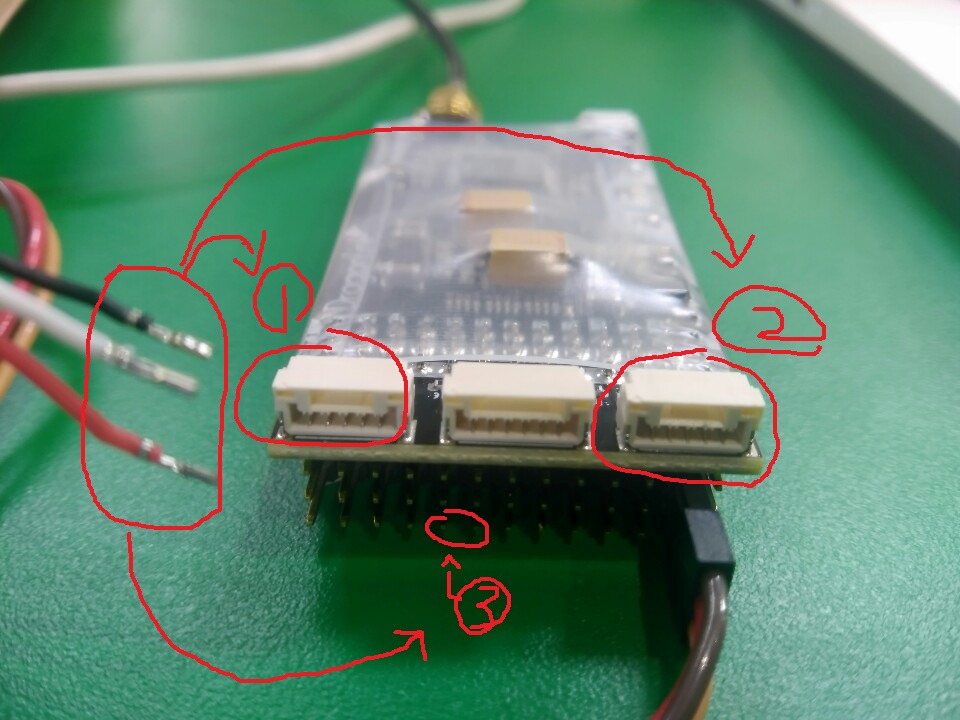
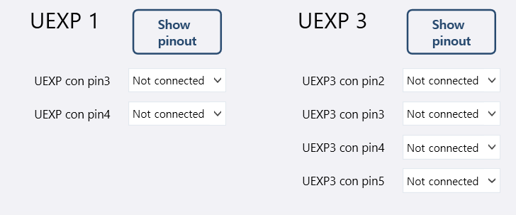
you‘ve set your DragonLink receiver‘s pins 5 and 6 as serial out and in correctly. that‘s what i meant when saying „physical pins“.

as i said a wired connection to your GCS might facilitate tracking down issues as compared to a bluetooth connection, it‘s just my opinion though. USB is one option.

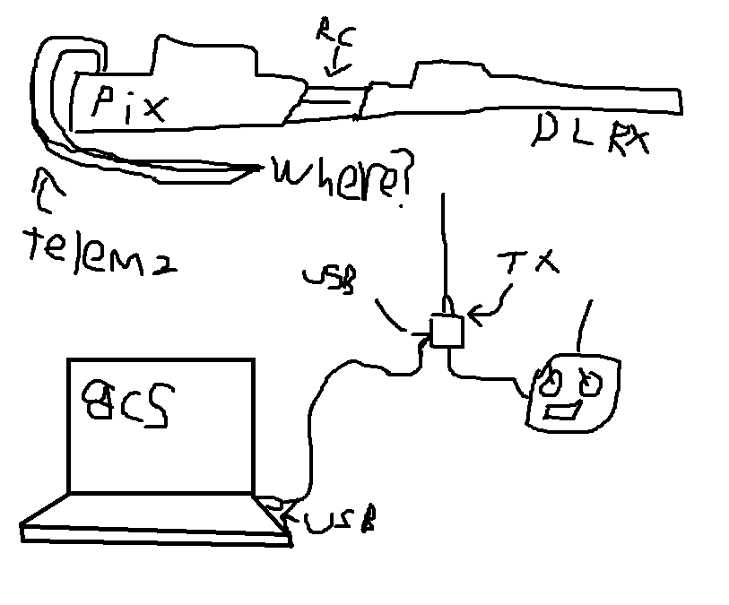
if you’re running your pixhawk’s serial ports on defaults, TELEM2 most likely is the port you want to use.

I am glad to have set pins 5 and 6 correctly.

So how do I do wiring?

i need to connect the TELEM2 port of the pixHawk to the DL Receiver.

Can you show me your wiring and DL RX TX settings?

This is the picture I understood.
is this right…?

I do not know how many times I need to wire the TELEM2 port and how to connect the line to the DL.

I’ve seen about 3 explanations and texts, but they all give different explanations. I do not know what is right.

sorry if i did not make that clear enough, no need to wire your pixhawk to the DragonLink transmitter additionally. when saying „RX->TX“ i was referring to the pixhawk’s telemetry port to DragonLink receiver’s connection, that might have been confusing.

basti.

Thank you.
I have some understanding of the TX part.

Finally, this is the question.

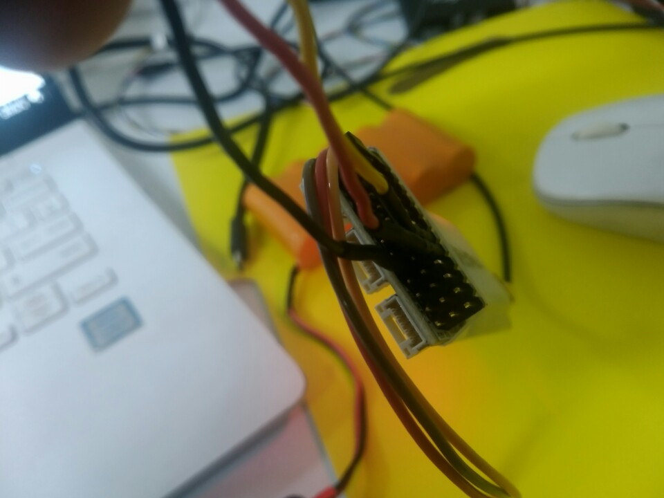
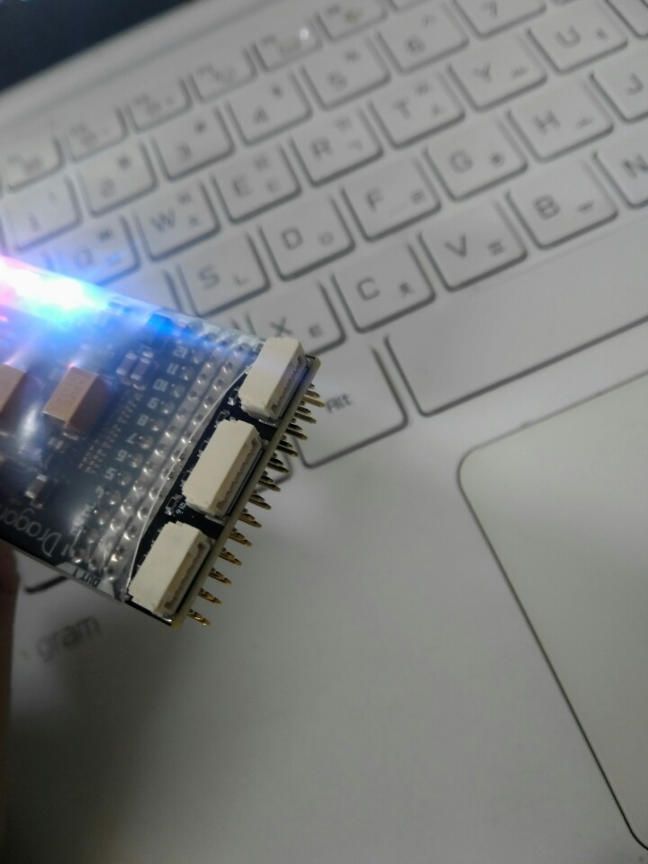
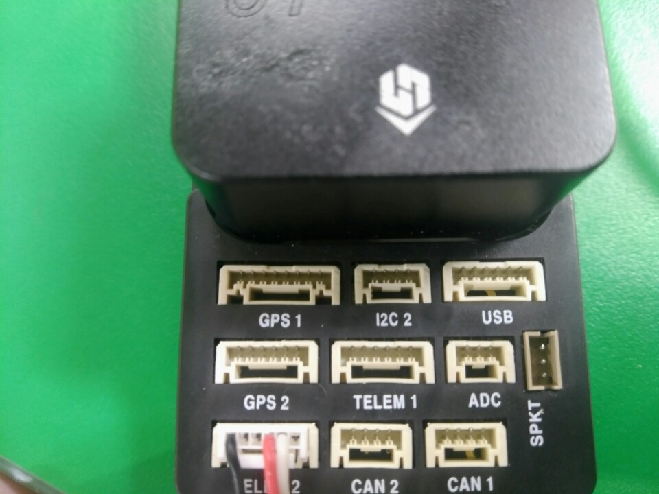
RX has three ports that look exactly like the Pixhawk Telem port.
Directly below, there are three pins to which the servo connector can be plugged, ranging from 1 to rssi. (vcc, gnd, sig)

Where should I put the line from this Telem2?

Some guide articles are here, some guide articles there, they are different. I do not know who to believe.

I am very afraid that I have been in the wrong direction so far.

When I connect the Tx to the GCS via usb, what settings should I have?

You mentioned RX and TX of TELEM2.

I saw the pinout of Pixhawk2.

Are you mcu_tx, mcu_rx?
Is mcu_Cts (tx), mcu_Rts (rx)?

depends on what you set in the DL reciver setup.

mcu_tx, mcu_rx = tx , rx

you only nneed mcu_cts and mcu_rts if you use flowcontrol.

Thank you.
As a result, I used the mcu_rx mcu_tx pin.

I attach my rx, tx settings and pictures for a more accurate diagnosis.

divi

rx03 tx02

double-check your baudrate settings match, as your DL receiver’s baudrate is set to 19,2 kbaud obviously:

rx_settings

you can use the “get status” button to check there’s valid telemetry-data on your DL’s receiver.

Follow that instructions, use the non flow control approach.

https://www.rcgroups.com/forums/showpost.php?p=40795313&postcount=75270

works like a charm with the newest firmware.

Thank you for your valuable information.
Do you have any other problem besides this?

Wiring or …?

get

I have these numbers

Is this normal?

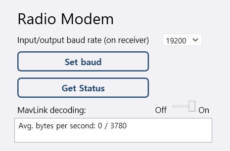
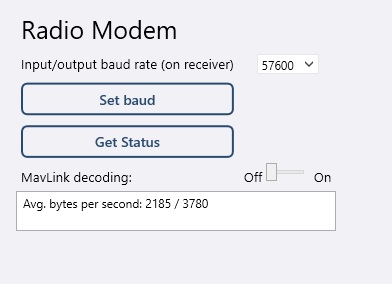
this is average used / available data rate. so there’s no data being sent via radio modem while that screenshot was taken. with an active link you will see the used data rate number increase accrodingly:
DL_rx_data
again, mind the baudrate settings of your FC’s telemetry port and your DL receiver need to match.

and you need to rebind your reciver :wink:
just reset everything to default and follow the instructions above step by step.
else its hard to find out what is wrong :wink:

I was half as successful in connecting the telemetry today.

Based on the slope of fc in the flight data, the instrument cluster moved together.

However, in the process of receiving the parameters, the telemetry could not get any parameters.

Were not you the case?

I sympathize.
This is very difficult and I do not know what went wrong.

I just like the above

I have had half the success.

And then I followed your link and fc turned out to be inverted and I did not get the parameters either.

Of course I did not forget to re-bind each time the setting changes.