Background
For the last couple weeks I have been working on a reference frame design of sorts, so I wanted to put the idea, with some context, out into the community for feedback. My particular specialty is designing and building frames. BoxBotix being the design with the most time invested (man years by now). I also happen to run FlyingFoam with my wife, so we have a few CNC foam designs as well. This reference frame design is an effort to capture some of the lessons learned from our experience, as well as what I have gathered in this, and other communities. It is not original. It is just a refinement of other ideas for use in the context of developing software and hardware in the ArduPilot community. Think of it as Iris meets Open Source.
General Goal
Create a frame system to support hardware and software development that can be built in under an hour with basic hand tools using 3D printed parts and off the shelf components.
Specific Design Requirements
- Released Open Source under CERN OHL
- Minimize the number of tools required
- Minimize the number of parts required
- Minimize glue required
- Custom parts should be 3D printable on a 6inx6inx6in desktop class printer
- Off the shelf parts should be easy to source in your region (E.g. Imperial tubes in US; Metric tubes everywhere else)
- Base design should scale to fit autopilot plus compute node up to Intel NUC size (4in x 4in)
- Base design should be multi-modal capable(Copter, Plane, Tailsitter, QuadPlane, Rover)
- Attachment of key components and payload(s) to frame should be easy and adjustable to allow for various configurations and easy field servicing
Initial Design
The above list is pretty close to what our design goals were with BoxBotix. The biggest difference is this will be an open frame with no dust or water resistance in the base frame. To get the speed and ease of assembly up we will be using mostly carbon fiber tube and limiting the number of 3D printed parts. 3D printing is slow and the parts can get heavy if you do not want to invest a bunch of time and effort in both the design and the tuning of your entire print process. Carbon fiber tubes are light, strong and easy to source these days, so lets prioritize their use for an easy win.
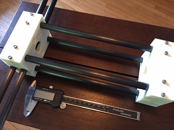
BoxBotix started with the concept of a BrainBox. It is pretty simple and it works. The BrainBox is just a box truss that allows various parts to be attached on the six faces of the box. BUT it has way too much print time and complexity for this kind of use and abuse. Pretty easy to simplify it in an open frame with some CF tubes instead of all the 3D printed parts needed in an enclosed design.
Picture of first version. Really strong. Too big, heavy and way too much print time required.
Annoying Details
- Starting with Copter. It’s an H frame. Likely use 15in props and 6S as that is what I have here. Pixracer and a compute node. Perhaps a Joule on Dev carrier. I figure if it can support that size and weight we can scale down easily enough. .
- I am using threaded inserts. M3 all around for M3 fasteners. They are a bit specialty but pretty easy to source these days. They do require a soldering iron for insertion, but if you are building a robot you should have a soldering iron.
- Threaded inserts require a min suggested clearance around all sides in order to keep pull-out strength. For our purposes on an M3 insert it is about 9mm clearance. That does not sound like much until you try to make something really small.
- I started with 0.5in OD pultruded carbon fiber tubes to try to keep cost down (and I have a bunch here). However, we are using raw clamping force for easy assembly and pultruded tubes do not like to be clamped. We may have to use wrapped tubes, which are more expensive and can be harder to source. V2 will use wrapped tubes.
- I went with a twin tube motor arm design to avoid needing to address a single motor arm tube wanting to twist in the mount. Makes the thing too big. Better compromise is likely to require a simple drill operation to run the 3mm screws through the tube as part of the box clamp. What needs to be done to make that doable is an easy way to keep all tubes jigged in position when drilling by hand. Working it for v2.
- Orientation of a 3D printed part matters. A bunch. The Z layer will be weakest due to inter-layer adhesion (or lack of it). I have become pretty adept at slicing up a solid part into pieces to allow for max strength, min overhangs and best tolerances when printing. V2 still needs some work to make it quicker and easier to print.
- I am designing around a “2 perimeter with 20% infill” assumption for printing. Might be able to tweak the design so it can be printed as a solid part OR CNC milled. That can come later.
- I print using IC3D ABS on several Lulzbot Mini’s. I do not like to change colors on the same part. I may print some smaller parts in black ABS, but if it’s a large working part I will use natural ABS. Color dyes can change the properties of filament enough to screw with your print settings. 3D printing is enough of a multi-variable nightmare, so I stick mostly to IC3D natural ABS. You can print with whatever you like. I like ABS as it has good service temp, it’s tough and I can acetone weld it.
The first version came off the printers about a week ago and I have been redesigning it in my head ever since. V1 was a tank as my first versions tend to be. V2 coming in the next week. Will drop an update once I get it done.
V2 Update 7/5/17
Made some progress yesterday. Not sure we can really call this a truss since so far I do not require any cross bracing to transfer loads. More of a box beam.
-Changed tube size to .57in OD to use the wrapped tube I have.
-Big box end redesign. Reduced the size of the box ends which brought the complexity, weight and print time down. Sitting at about 8 hours of print time across 3 print jobs for the base box frame. Also made tube clamps symmetrical so they are interchangeable. Much easier to put together from a stack of parts. Also means you can remove a couple screws to fold the arms in.
-Went old school and created motor mounts for the X mount on the Hacker motors I had. Need to address best motor mount design. Could be sourced off the shelf vs printed. Depends on tube size and what you have laying around for parts etc.
-Created lateral cross mounts designed to be attached to frame using zip ties. These will hold all your stuff. Pretty happy with first cut. Think these, and similar mounts, will be key to ease of use and keeping things manageable.
Total weight of base H frame is 13 ounces (~370 grams) without motor mounts. It’s a 650 class frame (almost square H) and will run 14in props on 4S. I kept the box much longer than it needs to be in order to have room for all the stuff going on it: AutoPilot; compute node, LIDAR, OpenMV, USB camera, and who knows what else. Think of it as a large breadboard for now. Going to get the circuit laid out with plenty of room to work, and then worry about size , weight and power later. Good news is it’s just a matter of cutting down the tubes if/when it needs to get smaller.
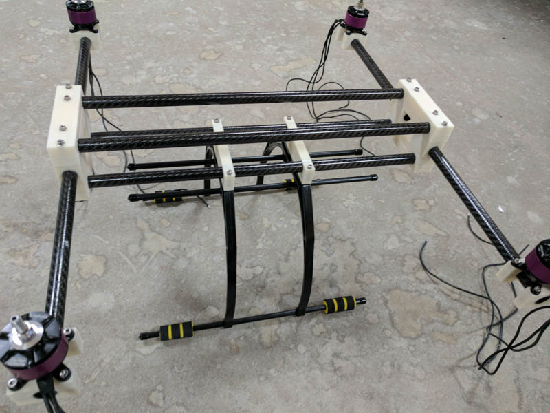
Next project is likely landing gear. Thinking crab legs under the box ends for now. Could easily adapt some of the off the shelf units to mount to our CF tubes but do not have any handy to design around.
V2 Update 7/17/17
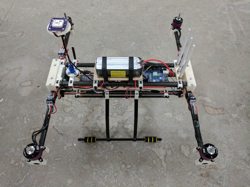
Adapted landing gear to bottom tubes. Worked well. Mounted everything using zip tied printed cross mounts. Also worked well with exceptions: GPS/Compass mount is not sturdy enough. Fix still in work. Also need to move WiFi antenna mount to bottom for better coverage. Bonus of the zip tie mounts is they make that move rather easy.
Base Frame with Landing Gear Ready For MaidenAUW = ~5 pounds with following config:
- 4 x Hacker A30-30M 550kv
- 4 x Castle 25A MR ESC’s
- 4 x APV 14x5 MRP
- 4S 6600mAHr
- PixRacer (ArduCopter 3.5 rc 10)
- FrSky X8R
- AUAV ACSP4 Power Module
- mRo GPS/Compass module
- SF 02 Lidar
- MinnowBoard Turbot Dual with SilverJaw Lure with Embedded Networks Ath9k mini PCIe WiFi and generic SSD
The off the shelf landing gear should work OK. The GPS mast is just OK. Too much wobble. Will design something better for this frame.
Maiden flight was just stabilized hover. Holds heading OK, but throwing compass variance and pre-arm compass errors. Suspect a bad unit. Will work on that for next version.
This will be the last update on this post. Next version will be the 12mm tube version. I will then likely come back to this bigger design and rework it for 16mm tubes since there are more common parts available for 16mm tubes than the .57in tubes I used for this version. Will also likely push this to 15in props and 6S so it will be capable of much heavier lift than the 12mm version.
Also need to figure out best way to share the files and docs. May go back to Wevolver for that support since GitHub does not really work well for this type of project.


