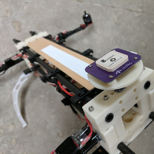
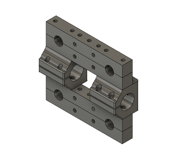
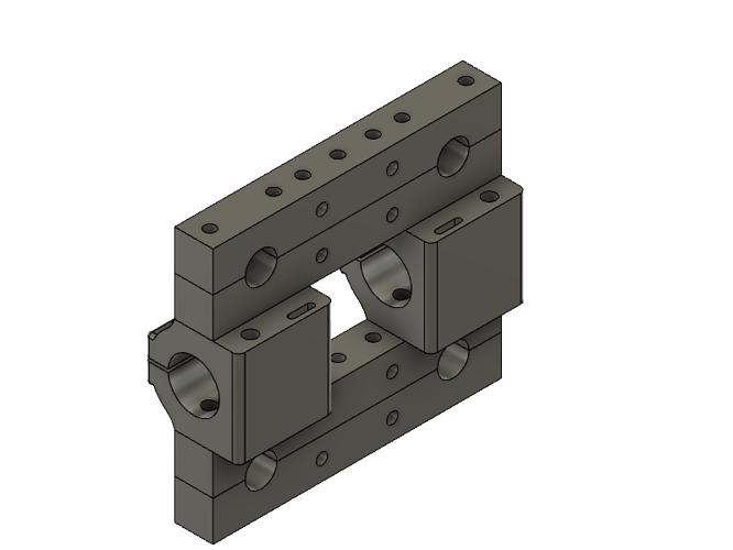
An update with build video and design files for the proposed dev frame. Still focused on Copter frame but Rover will be coming soon.
This is a continuation of Part 1 over here:
Updated Design Specs
Here’s the short list of feedback from the gitter hardware channel:
- Need frame size under 2kg and around 450 class
- Use Air Gear 350 set as base power spec (also similar to DJI Phantom replacement motors)
- 9-10 inch props on 3 or 4 cells
- 12mm motor arm tubes since there are off the shelf motor mounts
- 10mm box tube saves a bit on cost and size and is same as payload mounts for off the shelf gimbals
- 60mm on center box tube rails also same as off the shelf payload mounts
- Option for mounting off the shelf crab landing legs since they are cheap and easy to source
- Option for payload modules to slide and/or clip on/off front of frame
- Option for battery on rear of frame to balance larger front payloads
- Option to mount motor tube at different angles to support stretch or hybrid X geometry
To cut down on the blah blah in the post here is an album with the above put into action.
Base BOM
Frame (off the shelf)
(4) 10mm x 500mm carbon fiber tube
(2) 12mm x 500mm carbon fiber tube
(4) Tall Landing Gear
(4) 12mm Motor Mount
~$85
Frame (fasteners)
(16) M3 x 30 Cap Screw (button or socket will work)
(16) M3 Threaded Insert
*Add 8 more threaded inserts and fasteners for landing gear mounts
(8) zip ties
~$5
Frame (3D printed)
(8) Box End Clamps
(4) Motor Arm Mounts
(8) Cross Mounts, Zip Tie
~$30 (~6hrs print time at $5 per hour; have not shopped this figure yet)
Frame (misc)
Glue, 2 part PU or epoxy
Double sided tape
Material for platforms
~$10
Power
(1) Air Gear 350 Set
(1) 3 or 4 cell lipo ~ 4-5000MAhr
(1) 4 way PDB w/ 5V reg
~$200
~ $330US for built frame minus autopilot, companion and payload
Build
Goes together just like the older version in this video
Notes
- Completed a short test flight. Flies fine but needs more testing to see if there are any hidden issues.
- Carbon fiber tube diameter in my batch of tubes was +0.02/-0.5mm tolerance which is really bad and can require tape shims
- Still a bunch of design files to tweak. Mostly mounts and various accessory options.
- Rover will be next. Likely a two wheel skid steer to keep cost and complexity down.
Summary
I’ll attach the design files here in both step and stl. Needs more review and testing. I am sending a few printed kit parts out to alpha testers in the next few weeks. Version 1.0 should be ready after more testing. Likely a few months given the volunteer nature of the dev cycle.
Files and Printing
step and stl files: B4_1060.zip (326.3 KB)
Printing in ABS at 0.3mm layer height, 2 perimeter and 25% infill. No hard requirements set so you can vary as required for your needs.
Update 8/21/17
Files now have version for 12mm motor arms and 16mm motor arms
Pilot hole for M3 threaded inserts is 5mm. Some threaded inserts will not work We may need to reduce that hole size for other inserts to work. I am sourcing mine here:
Update 8/22/17
Changed the title from reference to dev frame as reference frame also refers to spatial coordinate systems like ENU, NED etc.
Update 10/15/17
Version 3 Files B4 1060 v3.zip (378.5 KB)
Change Log
- Reduced size/weight of Box End Clamps
- Arm Mounts Clamp (no need for glue)
- Accessory Holes reduced for M3 screws or M2 inserts
- Two versions for 4mm and 5mm OD M3 inserts
- Two versions for 10mm and 16mm arm tubes
- ESC mounting area with ziptie slot on the Arm Mount
More details in comments below…


