Dealing with Vibrations and harmonics... a competition

I am assuming a Pixhawk 2.1 and kit setups here and not the 2.0. The 2.0 has a known issue where the board the IMU is on sees high G loads and is prone to mechanical failure. There is also questionable isolation.

A: Harmonics of the foam damped board. The frequency would depend on the elastic modulus of the foam. This will tell you the wave speed. Worst mode shape would probably be in a normal direction to the surface of the board when the wave is in a stacked wave based on the compression of the foam. (board is moving up and down at the same frequency as the natural frequency of the foam)
There could be harmonics in the carrier board if it is not attached to the box well. They would probably be trampoline shaped.
-Only screwed in the corners.
-No support features where plastic presses on the board from the top or bottom.

If the carrier board box is not mounted well there will be vibrations put into the system
-I would mount it with 2-3 pieces of 3M VHB tape to a solid surface on the quad. The VHB tape won’t come unstuck and will damp high frequency vibrations from entering the system. One piece could cause it to sea saw which would introduce unwanted values into the system.
-If the box is loosely zip tied or loosely screwed, the play could saturate accelerometers and gyros when the props are at certain speeds and lead to irregular bouts of instability from sensors seeing too much noise.

Effects of vibration can be either mechanical where mechanical failure would occur. electrical or data driven.
Mechanical: Chip solder connection breaking or wires breaking loose
Electrical phenomena could occur (induced currents in wires from vibrating in a magnetic field)

Data issues could come from noise on accelerometers and gyros leading to larger damping values being required in PID control. Uncontrolled harmonics could overwhelm accelerometers and lead to a condition where the IMU does not know which way is up. This could lead to unstable flight either all the time or when props are at certian RPMs. The instability could cause a condition where variations in prop RPMs introduce noise at critical times which could lead to a crash.
Vibrations could lead to high noise conditions on altimeters where a resonant cavity condition occurs inside the UAS body or the altimeter could become a resonant cavity from it vibrating and give wild pressure readings. This would give errant altitude readings and could bring a UAS down.

Measuring resonant frequency:
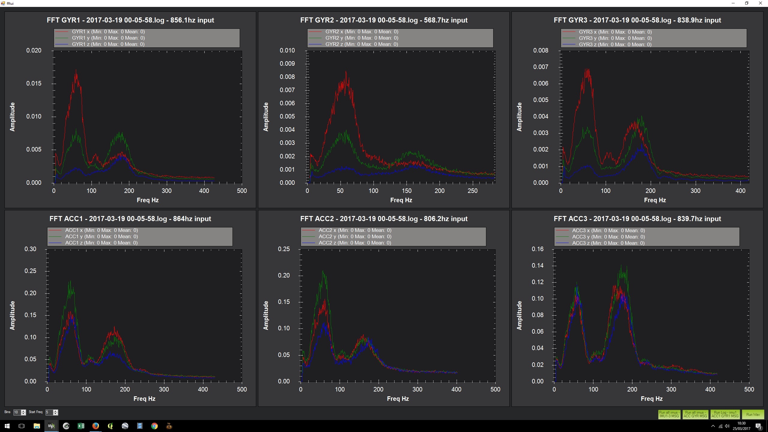
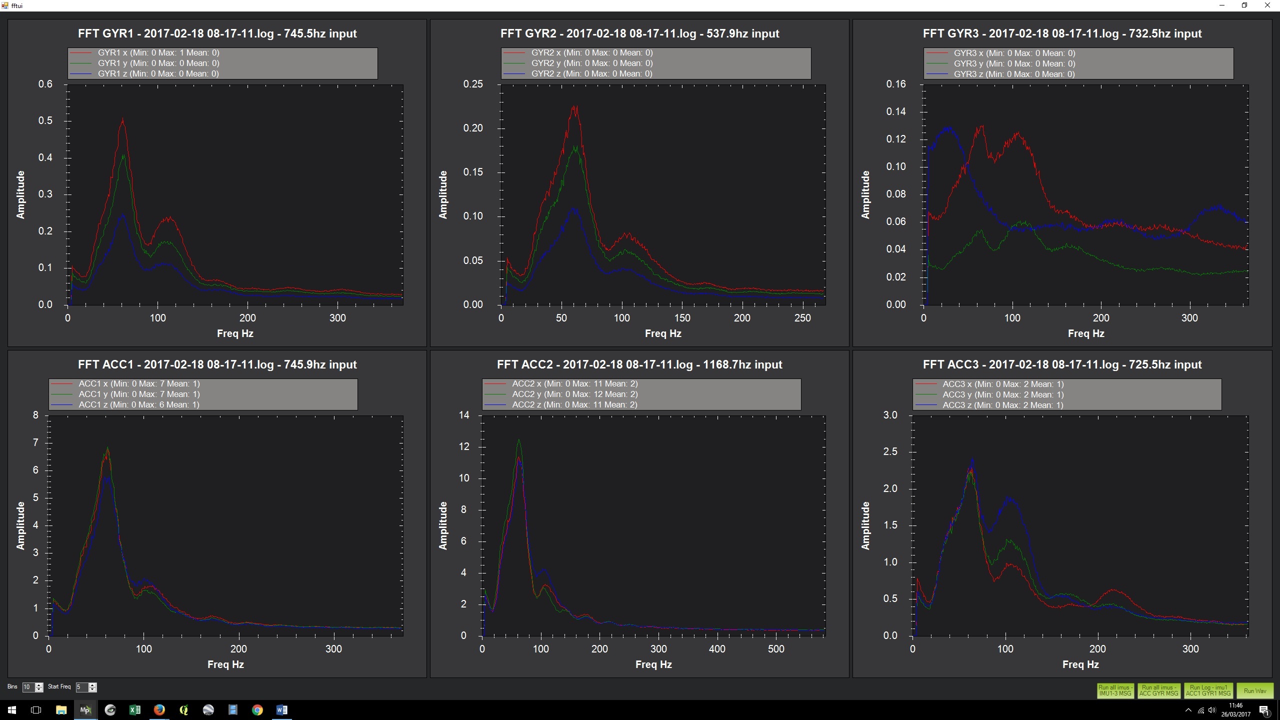
There are standard equations for beams and other shapes available. You could use mission planner and have it log vibrations with high resolution. You could place an accelerometer hooked to an osciloscope and do a tap test where you flick or tap the part and see what its natural frequency is. Whatever you do, know that stable sensors are happy sensors.

If your airframe has vibration and you want to lower the amplitude: If it is a low frequency < 50 Hz it is best to use some sort of stiffening to increase the resonant frequency. Get creative with 3M VHB tape and carbon fiber sheets or paint stir sticks to stiffen the structure.
If the frequency is over 50 hz or so use sorbothane or some sort of low durometer rubber to damp out the vibrations. Stopping high frequency vibrations from entering the system is the easiest way to fight them. VHB tape to attach components is pretty good at damping out high frequency vibrations.
The key here is for low frequency, stiffness is required and for high frequency damping is needed. If you want to read more on this look up rayleigh damping. High frequency vibration needs a lower amplitude to overwhelm a sensor as the accelerations produced by a high frequency vibration are higher than that of a lower frequency vibration.

An issue here is that most people lack the mechanical engineering background to engineer out vibrations. Trial and error will get you a long way if you know what to watch out for and do sufficient tests prior to flight. Basically cantilevers are bad and sensors should be mounted on a stable platform so they don’t get noisy signals. If you have a large board mounted to something, use more than 4 screws in the corners and try to get one in the middle. If you have a rectangular board you are mounting, try and secure it slightly off from the middle so you don’t get a M shaped vibration. 2/3 along the way is a good place.

Silicone caulk (The bathroom kind that is 100% silicone works pretty well for damping and filling things) It also should have a good dielectric so it is not conductive after it dries. It can get pretty messy if you ever need to get access to components at a later date. Best for if you are never going to need access to something again. If you need to ever get access again use sorbothane or a different low durometer silicone based rubber.

Other tips
If you have any sort of mechanical play on a sensor that is mounted i.e. an accelerometer that is zip tied down loosely, you will get lots of noise in the sensor reading and the autopilot may not be able to understand what the average value is if the extremes of the noise are past the max the sensor can read. This is a similar concept for a sensor mounted to a surface that can vibrate. If you can minimize the amplitude of movement, the readings will be better and the autopilot will not need to struggle to understand the reading. If you need to attach a sensor to the frame of your quadcopter know that the frame will vibrate with high frequency and you should use some 3M VHB tape to attach it so you don’t transfer the high frequency vibrations.

I would need better info on the cube to tell what the worst natural frequency is. The worst mode would probably be normal to the sensors that are mounted on the plate that is isolated with foam it would be in the direction that is normal to the surface in a vertical back and forth oscillation. Info I would need is the exact foam used, how the foam is attached to the cube. If the foam is glued on top. If the foam touches the sides of the cube when the lid is on. These things would let me calculate the natural frequency of the isolated assembly.

One other thing. Balance your props. Vibration from unbalanced props can be a large source of vibration. It is also easy to deal with.

Background: I’m a mechanical engineer and was a CAD designer through college. I spent a lot of time trying to understand displacement transmissibility.

4 Likes

One of the harmonics of the Pixhawk 2 is approximately 80hz

This affect can result in unstable flight (motors pulsing, arms dropping)

The affect can be measure using the FFT function in mission planner with high speed logging enabled.

One way to protect the airframe is to change the resonance frequency of either the frame or flight controller. In the packaging there are several pieces of foam one of which is the same size a the cube so i assume might go inside the cube to adjust the dampening, some of the other pieces can be used to soft mount the Pixhawk. The other method i use was to place of foan tape between the arms and frame which changed the resonance frequency of my frame from 80 to 130 hz

that’s an interesting number… where is the data to back that up?

Don’t have any actual data the only thing that i can say is the closer to 80Hz the worse the quad flies.I was fiddling with so much other stuff the logs are useless evidence

ok… data or it didn’t happen :slight_smile:

Is this compettition still open?

go for it Charlie with the answer of 60 and 180hz.

Ok, here goes…

A. Please define each of the harmonics that can affect the Pixhawk 2.

The harmonics which can affect the Pixhawk 2 are those for which the internal damping is not effective. Passive vibration damping systems have a natural frequency, or resonance, defined by the stiffness of the ‘spring’ and the damped mass. At this frequency, the damping will not function effectively and may amplify vibration.

Below that frequency the efficiency of the isolation will drop, and above it will increase. The stiffness of the damping material determines the shape of the transmissibility curve. Stiffer materials show less resonance at their natural frequency, but the roll-off in vibration isolation above that is shallower. So there is a tradeoff, softer damping is more effective at reducing high frequency vibrations, but at the cost of being more susceptible to resonances.

Harmonics of the natural frequency will also have an effect, particularly those below it. The Pixhawk 2 has 3 onboard IMUs, of which 1 and 2 are on the damped section. Using the FFT function in Mission Planner, you can therefore compare vibrations from the frame (assuming the PH2 is hard mounted) to those being transmitted through the damping material.

Here is an FFT of a 2 minute hover. ACC3 shows the undamped vibrations reaching IMU3, there are peaks at ~180Hz and ~60Hz. The amplitude of the peaks is 0.12-0.14. When comparing ACC3 to the ACC1 and ACC2 graphs, the 180Hz peak is reduced (by about half) but the 60Hz is amplified (almost double).

So it appears that the natural frequency of the Pixhawk damping system is around 60Hz. Harmonics of this frequency, particularly sub-harmonics, will also be less affected by the internal damping (15Hz, 30Hz, 60Hz, 120Hz, 180Hz, etc. etc.), and will add to the vibration at the natural frequency.

In a multirotor the vibration sources (props/motors) are not in phase with each other, but as the rpm changes, they might pass through moments of being in phase (or out of phase), which could cause moments of increased (or decreased) vibration.

B. What is the effect of these on flight?

In general vibrations cause problems with position estimation (accelerometers) and attitude (gyros). Severe vibrations cause obvious problems with erratic behaviour in flight. If the vibrations are not so severe as to interfere with the ability of the craft to fly, they can still cause problems in GPS assisted/automated flight modes. Poor position holding, causing the craft to drift in one direction or the other when holding position, is one symptom. Increased susceptibility to wind or turbulence causing unusual or hesitant appearing automated flight is another.

Hitting the frequencies or harmonics of the Pixhawk 2 can cause a sudden jump in vibration levels. For example, if the prop RPM in the hover is close to the natural frequency or one of its harmonics, flight characteristics may be mostly OK, but exhibit periodic divergences as frequency and phase relationships change. When a divergence becomes severe enough to get through the noise, the motor rpm correction will probably change the dynamic relationship and restore good control.

Here is an FFT of a fairly long flight – same model as the FFT above, but an earlier incarnation which was not flying in a confidence inspiring way

C. How can someone measure this on their airframe?

Using the FFT function in Mission Planner. To do this you need to:

  1. Enable full or high rate logging using the LOG_BITMASK parameter
  2. Carry out a test flight
  3. Download the logs
  4. Ctrl-F in Mission Planner to bring up the ‘temp’ menu
  5. Hit the FFT button and chose ‘run all imus – ACC GYR MSG’
  6. Compare the ACC/GYR3 results with the other two IMUs
    (The amplitude is relative, longer flights will produce higher numbers. Also be aware the scale will be different for each of the charts by default, this needs to be taken into account when interpreting the results)

D. If your airframe has vibration in these bands, what can be done to protect the system from this?

Propeller RPM, or possibly a resonance excited in the frame by the prop RPM, is going to cause these harmonic frequency related problems. If the frame is stiff enough, then changing the prop RPM is the simplest way to investigate or alleviate the problem. This can be achieved by changing the prop size, pitch or number of blades, or the all-up-weight of the model. If that cannot be changed enough to reduce the problem then an additional damping system could be used, chosen to be effective at the problem frequency.

13 Likes

Charlie drop the mic!

Thanks for the info Charlie - very informative

Great, thank you very much

foan tape, how to place that ?
between the arms and frame ? hard to understand.

So this was called a competition, who is the winner…?

1 Like

Anyone who reads the thread…

2 Likes

Assume it’s still up for grabs…?

WOW! This is a GREAT thread. Has anyone NAILED down the best anti-vibration setup?

The best has been proven to be hard mounted…

1 Like

@proficnc I’d love to see some logs and videos from your hard mounted flight tests.

The best setup is the one where motor/props frequency when hovering do not match the natural frequency of the frame since the mount material available for the flight controller mount do not always allow to damp the vibrations of the system.

Its quite typical that the vibration is worst at hover when the motor/props frequency hits the frame natural frequency. However I have found out that with larger drones (18") in high speeds the turbulence caused by frame and thrust can cause high vibrations in the frame even when the motor/props are not rotating in the natural frequency.

Best way to avoid that is to make the frame more stiffer so it wont flex even on high forces caused by low/high pressure changes.