Hi All,
I am currently trying to configure the the current & voltage sensor to read from POWER 2 pins of CUAV V5+.
I have change the parameters for Batt1 & Batt2 are following
BATT2_MONITOR = 4
BATT2_VOLT_PIN = 0
BATT2_CURR_PIN = 1
BATT2_VLT_OFFSET=0
BATT2_VOLT_MULT=31.49968
Batt1 sensor’s are working fine but Batt2 current & voltage values are showing on mission planner.
Any one have any idea why this is not working?
@Michael_Oborne @xfacta @amilcarlucas
Did you reboot after setting the parameters?
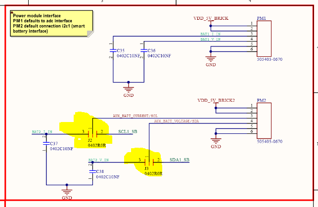
By default the V5+ Power 2 port uses digital data input from a “smart” battery , I2C.
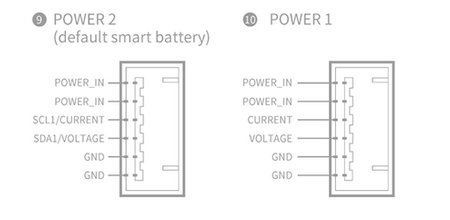
To use an analog voltage and current input for Power2 you will have to find on the carrier board these jumpers, possibly with a zero ohm SMD resistor in place.
You would have to mover each of those from 1 and 2 to jump 1 and 3 instead.
Hello @xfacta ,
Is it same for CUAV V6X Power 1 & Power 2(both are mentioned as I2C?
I have both current & voltage sensors are analog output.
Attaching imaging for reference.
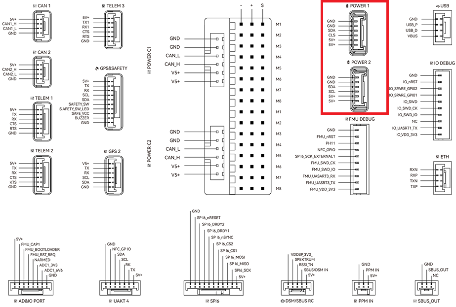
CUAV dont list the schematics for the V6X so I cant tell if analog would be possible.
You should just buy the CUAV I2C power brick (one should come with the flight controller) or the Mateksys one, or one of each
http://www.mateksys.com/?portfolio=can-l4-bm
thanks for replying me but we can not use default power brick because my input voltage is 100V & current consumption almost 450A. so we have created own analog output sensors.
40KW ? Is that a cargo or a manned craft?
Check if the RSSI pin supports an analogue voltage input, you could feed a voltage divider into that and log it, or possibly even change a voltage monitor pin setting to be the RSSI pin.
I have tested with CUAV V5+ ADC pin for BATT2 volt & current but its not working with following parameters
Batt2_Volt_pin : 11
Batt_Curr_pin : 12
if anything wrong please give suggestion.
But for V5+ you need to modify those jumpers on the carrier board and you can use the Power2 connector.
In the circuit diagrams it doesnt look like the power2 analog inputs are related to the spare ADC 3.3v and 6.6v inputs.