This is a follow on to post a I made about not getting current telemetry.
I’m using a CubePilot Mini Power Brick. I swapped out both the Mini Power Brick and cable to verify that these were working properly. No change after the swap.
I did however notice something unusual. The telemetry does register current when the flight controller is powered only by the USB. However when connecting the main battery, the telemetry for current drops to zero.
This can be observed in this bin file:
The only thing I’m doing different here than with the quad-copters I’ve build with the CubePilot Mini Power Brick is that I’m using the AirBot Mini Carrier Board.
The AirBot Mini Carrier Board has solder bridges for the RCIN voltages - and as I’m not using RCIN, I’ve not soldered them. (I’m using a TBS Crossfire RX connected to Telem-1)
I’d appreciate any help, comments or ideas. Thanks!
It’s fairly common that FC’s keep input side electrical different than output side. In that way less likely to burn everything out when there is a short somewhere in the wiring or component.
Example: In my FC I power FC from Battery Monitor but also have a BEC (with same ground (-) connection powering via USB port. This also provides for some redundancy as FC will switch over to other power source in event of main source failing.
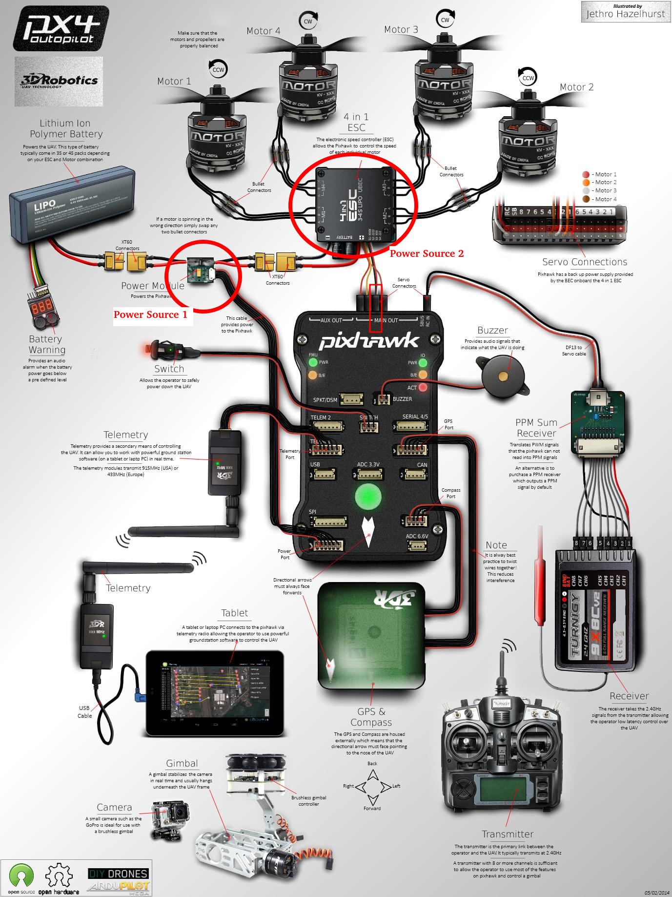
As it happens, my configuration is exactly as what is shown in your diagram. The only difference is that I’m using a single ESC and motor - as it’s a single engine airplane.
I have a 5V BEC powered from the PDB that feeds the servo rail on an AUX port.
My ESC control signal is connected to Main-3, and powered by the PDB.
My RX is connected to Telem-1 and my GPS is connected to CAN-1.
In that log, are you powering the setup by USB then plug in the battery for about 10 seconds, then disconnect the battery?
Or is the battery plugged in the whole time?
I’ve checked the parameters (including pins) and they look good.
Maybe try this → plug the power connector/wires into the other power socket.
On every Cube carrier board except that particular Airbot one, the Power1 and Power2 are the other way around.
Another interesting fact I’ve found is that the specs call for 5.3V not the regular 5.0V
Is your BEC in fact 5V as you have stated or the required 5.3V ?
Yes, but that’s how problems can occur:
If the BEC provides the required 5.3V but the MP is from another project / FC and only provides 5V, then a current could potentially flow through the FC trying to power the MP. As it is not designed for that purpose a significant voltage drop will occur internally. This means it can’t function as expected.
This is also the effect Joseph describes.
In the log, during USB connection the board voltage is reported as about 4.40v, quite low.
During battery connection the board voltage is 5.24 which is very acceptable.
Do you mean the power module (power brick) ?
Joseph is using the standard cube power module, and even swapped it with another.
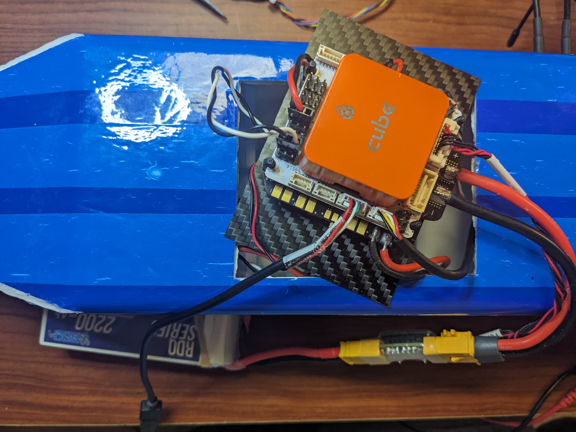
I can see in the photo it is definitely the correct type, and the parameters have the correct values.
I dont think this is an issue with the power module or cable.