Cube without Internal damping

Still some long cables or bundles that could be tied down a bit more. I started circling them, but then I realized I was circling nearly every wire in view…

It’s OK to be neat and tidy, or even a bit messy, but everything has to be secured to the frame in a copter. Wires cable tied to other wires just means there is more mass to move around and vibrate. They need to be tied down to the frame, but with enough flexibility at the ends so they wont break at the connectors or transfer vibrations.

For example, those PowerA and PowerB wires between the Cube and Mauch - they need to be secured to the plate. Probably at their mid-point would be sufficient in this case. Otherwise they will vibrate and shift around and be like a lever amplifying their vibrations at the carrier board (and onto the Cube).

Here is an old copter of ours, it’s not a perfect example but you should be able to get what I mean.
You can see the GPS and Telem wiring are secured at the base plate (where I put an arrow) with enough free/flexible wire to allow freedom but not so much the wires need to be supported by the flight controller.

It’s not obvious in this picture, but the servo wires and power wires were also secured to the base plate.
Ignore the bits of grass and debris :slight_smile:
Ignore the blue and black wires sticking up in the air, I think I had just added yaapu telemtry and I tidied up those wires later - they are certainly different now.

2 Likes

Hi @xfacta
as per your suggestion i have made all cables tied up with frame body where ever is is possible and same images is attached here for your reference.

i just marked the tied point with frame where ever possible and no where pulling cable.

but still i had same issue that Z axis vibration peaking up badly on isolated IMUs. but NOT on Non isolated IMU.
there is not such vibration on X and Y axis as i already told .propeller balance also checked.
here is the log for yesterday test flight.

the above log is to collect FFT data
i have got peaking around at 60hz

but as per previous flight log which posted earlier on this topic here it was shows there was small amplitude at 30Hz so based on that FFT data i have configured harmonic filter setting like this and performed this again yesterday. but yesterday was there is no peak amplitude at 30 and it started at 60hz.

here is the previous flight FFT graph and harmonic configuration.


still drone is under control to fly even though there is more vibration know this should not we try but want to know the flying behavior’s when there is excessive vibration. log for flying with excessive vibration.

here is my attitude angle controll on ROLL and PITCH

i just seeking for your help to improve the system …i want to know harmonic notch filter frequency should be go with 30Hz or 60hz ?

Good work with the wiring.
It looks like there might be too much double-sided foam under the flight controller. Maybe that’s something to explore.
I see what you mean about the high Z vibrations. You will probably need some different flight controller mounting system, like that 3D printed one I referenced.
There is clipping in the isolated IMUs so dont fly again until you are sure Z axis vibrations are improved, or you risk a fly-away. Clipping indicates vibrations have exceeded the physical limits of the IMUs.

The good news is attitude control is still very good for such a large copter.
And the harmonic notch filter is working well at squashing the noise, even if it is a bit overkill with a lot of harmonics specified. I guess the wiring changes you made got rid of the 30Hz noise and we are left with the harmonics now, because 30Hz is still around what those props should do for hover.
Based on that log I would simplify and adjust it to:

INS_HNTCH_BW,40
INS_HNTCH_FREQ,50
INS_HNTCH_HMNCS,3
INS_HNTCH_REF,0.16

For this result:

Also I’m thinking Rate P&I values could be higher and D could be even lower based on the activity I see in that log.
But I’d prefer to see the physical vibrations reduced a little further, the new filter settings go in, and a new test flight before changing any more PIDs.

EDIT:
MOT_THST_EXPO might be a bit high even for those props. If you did tests and that is what you calculated, that would be great (and I could save it as a datapoint in my MOT_THST_EXPO data collection)
However I suspect it should be more like:
MOT_THST_EXPO,0.82

The filter was like this before my suggested updates. Lots of phase issues not shown in this graph too.

I took a look at your log and photos, and I think the gel pad may not be suitable for you.

I think you can try this, but be sure to pay attention to safety! Stop immediately if there are any problems! And this is just a suggestion, I think it might suit you. Your VIBE is ridiculously large and your gyro is a mess. If there is nothing to change in your frame or motor, or if someone else has successfully used your frame, I think you should focus on trying other external damping.

In my limited experience, only one large copter allowed me to stick the FC with built-in damping directly on it, and it had huge 68-inch props. And after the RPM increased, the vibration became unacceptable.

If you use 3D printing, be sure to pay attention to the temperature! Remember!

This is the effect of my friend using this shock absorption platform. I didn’t test it directly, but I also recommended the same thing to my friend.
My friend used 6 22-inch T-motor kits.
In the picture, the log on the left is after using the shock absorption platform.


1 Like

its came up with cube orange+ flight controller itself and also it has small size foam tape also you are recommend to use that instead of this bigger one?
infact i have stared mount the cube orange+ with rubber damper only and had flight too. but same Z-axis vibration was huge. but satisfied thing was with damper i don’t see the clipping.


here is the vibration graph for all IMUs.

After this flight only i have requested help to Philip Rowse and he strongly recommended NOT to use these kind of Rubber damper and it must be hard mount and see.

so as of now you suggest to keep the current harmonic filter setting until clear the vibration issue. after vibration issue cleared your harmonic filter setting has to replace?

i will try any other method to try reduce the vibration and let continue the testing.

This MOT_THST_EXPO is based on initial parameter result by the mission planner based on the Propeller size and Batt voltage.

thank you for your support @Ben_bili
i have already working on frame side to improve what are the source of vibration that can be minimize.
and stared working on this anti vibration mount on 3D print.
i wonder if 3D print will not get broken from continuous frame generated vibration. you have any recommendation for the 3D print thickness.
As i replied to the @xfacta Philip Rowse who manufacture of Cube pilot who strongly recommended not to use rubber damper for this FC.

what is your suggested temperature for 3D print ?

I’m sorry, my friend used PA-CF as the material and used 0.2mm as the layer height. I don’t think his reference value is great, as PA is a difficult material to 3D print. If possible, I think it would be more appropriate for you to use CNC parts, although they are very expensive.

What I hope is that you pay more attention to the temperature of the environment, as PLA will soften at 50°C. If you are concerned about strength issues, you can consider setting a larger fill rate and wall thickness for it.

I don’t think there should be any strength issues unless you plan to use it for a long time. In this case, I hope you will definitely use CNC parts.

The shock absorption platform you are using will cause the CG to be too high unless you install very heavy counterweights under the upper platform. I don’t know if this is why Philip Rowse reminded you, he may have a deeper understanding of these issues.

But you might want to take a look at my article. If you use a rubber damper, then you definitely need to pay attention to your CG position, otherwise the FC will almost certainly sway on top.
Regarding the shock absorption of large drones, I hope to add it to the wiki - General / Website and Documentation errors - ArduPilot Discourse

I would agree using that type of 3D printed mount has done a good job.

Your friend would be able to further reduce the vibration be removing that USB connection and finding a smaller more flexible USB connector. Search your favourite online stores for “micro usb flat cable flexible”
And paying more attention to the wiring, which all needs securing.

The sort of antivibration mount you have is very basic and OK for use on small cheap copters. I would avoid it even for basic usage. Where I have needed a basic antivibration mount I used a 3D printed version that angles the damper balls so they are not stressed (see in my earlier pic). Yours wont offer uniform damping in all directions. You can see the damper balls are already stretched.

Get that other mount 3D printed and try that, I’m sure it will be a lot better.
To allow for high ambient temperatures you could get the 3D printing done with ABS.

The official recommendation is to ALWAYS hard-mount the Cube and carrier but there are exceptions to that rule, and it is common to soft-mount the Cube and carrier in high vibration situations. Every case can be different, and there are exceptions to every rule. We have plenty of cases on these forums where a Cube needed antivibration mounting.

NO. Put in my recommended settings right away. They will do an equally good job of filtering noise but with less overhead. Once vibrations are under control we can re-assess the filtering and hopefully settle on something that can remain in place for ever.

Yes I understand. As more data has come through over the last few years, I would be very suspicious of going over 0.80 for MOT_THST_EXPO for any props. I’ve been refining the formula used in that calculation and that’s why I recommend
MOT_THST_EXPO,0.82
since it is not a big change from what you have now, and also not far from a line of thinking that says we shouldn’t go over 0.80.

In the original Initial Parameters spreadsheet, that was converted to the plug-in in MissionPlanner, I used a formula to calculate MOT_THST_EXPO based on Leonard Halls experience and knowledge, and the formula gives an approximation of course. In reality different props may deviate from the formula. Some ESCs even affect the real outcome.
I’ve been working on a new formula that might be a little closer to correct in more cases, based on tests that have been occurring. The data is not complete yet, but I have enough to adjust the formula a bit and still produce reasonable results that are a closer match to actual tests.

Here is the link to the current spreadsheet. The new formula is used in the “4.0+” section and the old formula is still in the “3.6 and earlier” section as a reference.

I did remind him to organize these cables, but he didn’t seem to take it to heart, and I think maybe it’s not time yet. That USB cable is only used for downloading logs, and it will be removed after the download is complete.

I think that for larger drones like this, any 3D printed shock absorption platform that is not made of PA or PETG should be avoided. PLA will have problems at high temperatures, and ABS is… I have tried ABS printing many times, and in the end I found that the 230°C given by many manufacturers is not suitable. After I raised the printing temperature to 270-280°C, the adhesion between layers improved a lot. I think the manufacturer may have provided us with the temperature used for injection molding, and the environment of 3D printing is very different from injection molding.

Such a high temperature without a warm air blower to provide a warm atmosphere, ABS will almost certainly warp. I have calibrated the temperature of my 3D printer with my multimeter. I think if it is not a 3D printer with a warm air blower, you should not try to print ABS and use it in places where high reliability is required.
If you try to print ABS at 230-250°C, it is likely to break easily.
Of course, a slower printing speed may be fine. My printing speed is usually between 30-50mm/s. Slowing down may improve this problem, but I don’t want to wait.

And I have a guess that may not be correct.

I’m worried that tilted dampers will cause this problem. The picture is a bit exaggerated, don’t mind too much. Of course this is just my guess, and I have no evidence that this problem will occur.

That’s true for every drones I made using Cube which had the propeller size larger than 28inch. For the mass production, I had to ask Hex to replace the “default” foam to the other one.

1 Like

Hi @Ben_bili
As per above statement the sway will happen in lateral axis which is X and Y direction right. But in my case the main vibration happened in only Z- axis.

If added weight to the damper plate will arrest z axis vibration!

Oh no, you misunderstood me. What I meant by sway is rotation, the FC will rotate frequently around the CG as the center. You will definitely see crazy swinging curves in the gyro of the imulog, not swaying on acceleration.
Of course, increasing the weight of the counterweight can also compress the rubber ball to improve the shock absorption effect. You can try it, but all weights should not exceed 200g for four such blue rubber balls.

@xfacta sorry for taking long time here to update.
i have decided the to do same test on another new set of cube orange+ on different drone but similar type drone.
this time i have mounted with less thickness foam tape which come with cube orange+ boxes . Last time you mentioned the issue may be with large foam tape. Images attached below.

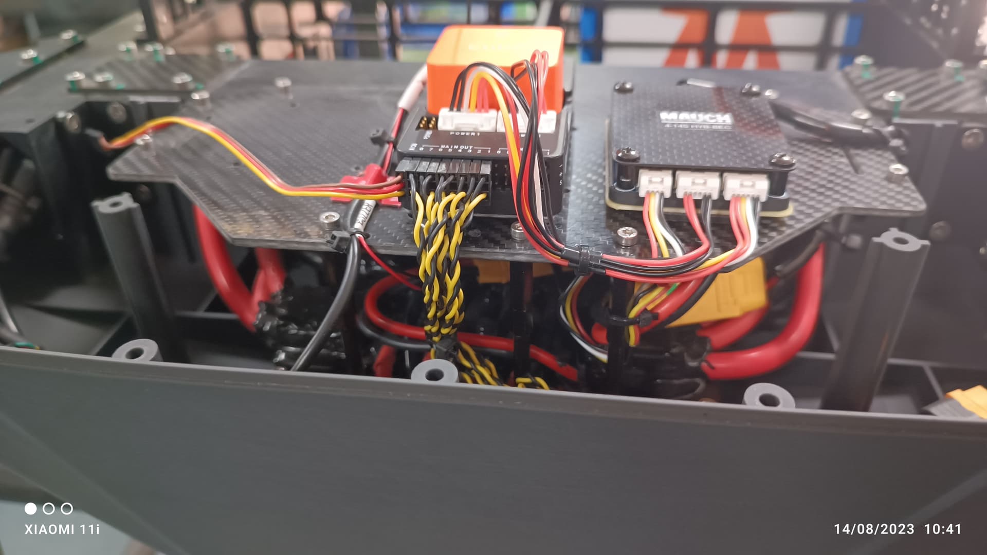
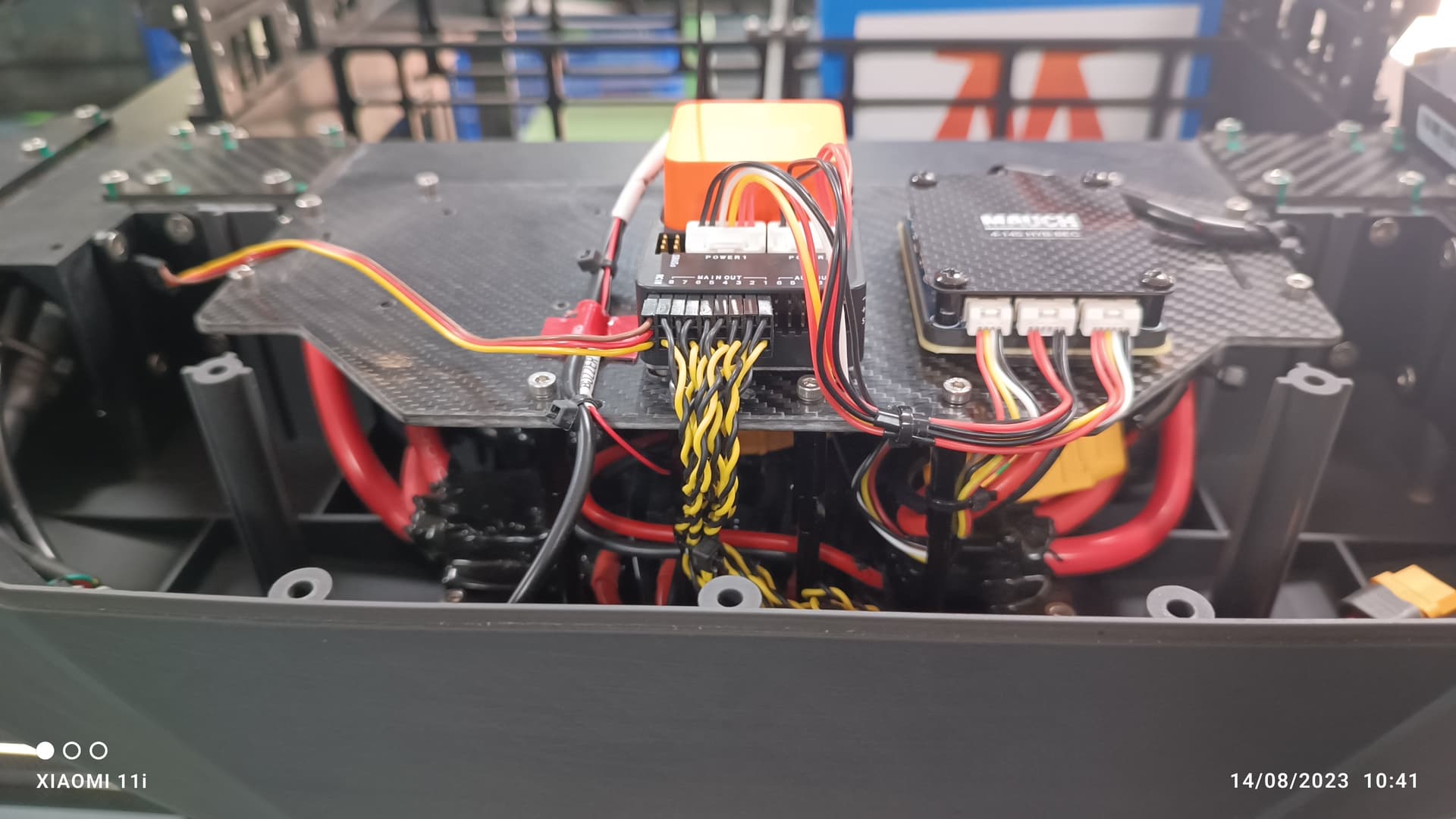
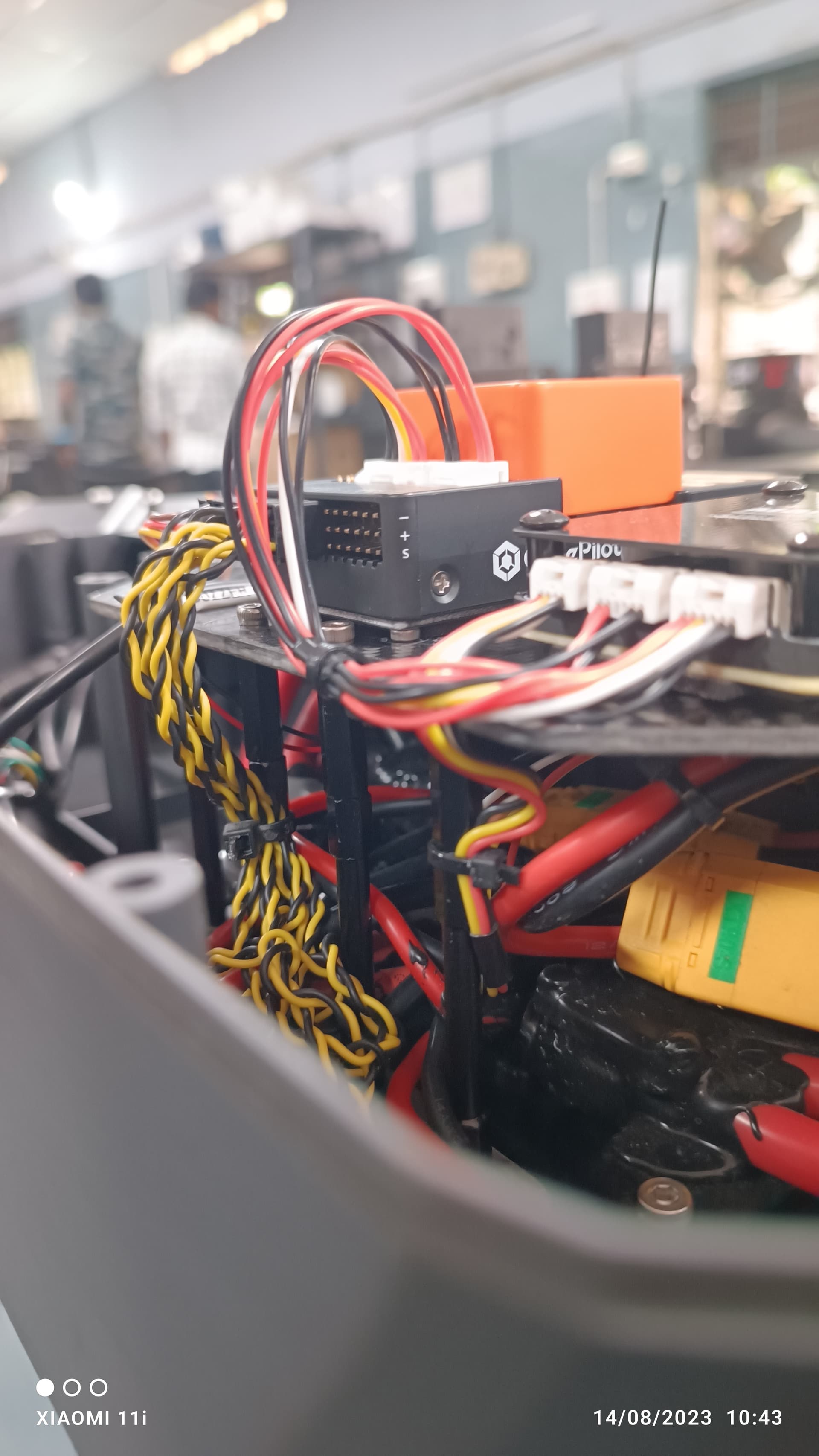
You can notice in the image i have added 4 spacers to stiff the autopilot carbon fiber plate with airframe. this i did not done this on previous airframe.

today i had test flight with all initial parameters loaded and noticed that Z axis vibration is very much improved compared to last time .

last time IMU0 and IMU1(isolated IMUs) goes more than 90m/s/s with more clippings on both IMUs . please refer in this topic for last Vibration Level.

Today both Isolated IMUs goes only 40m/s/s Max even we flown upto 15m/s speed in stabilize as well as Guided mode. as shown in the image below.

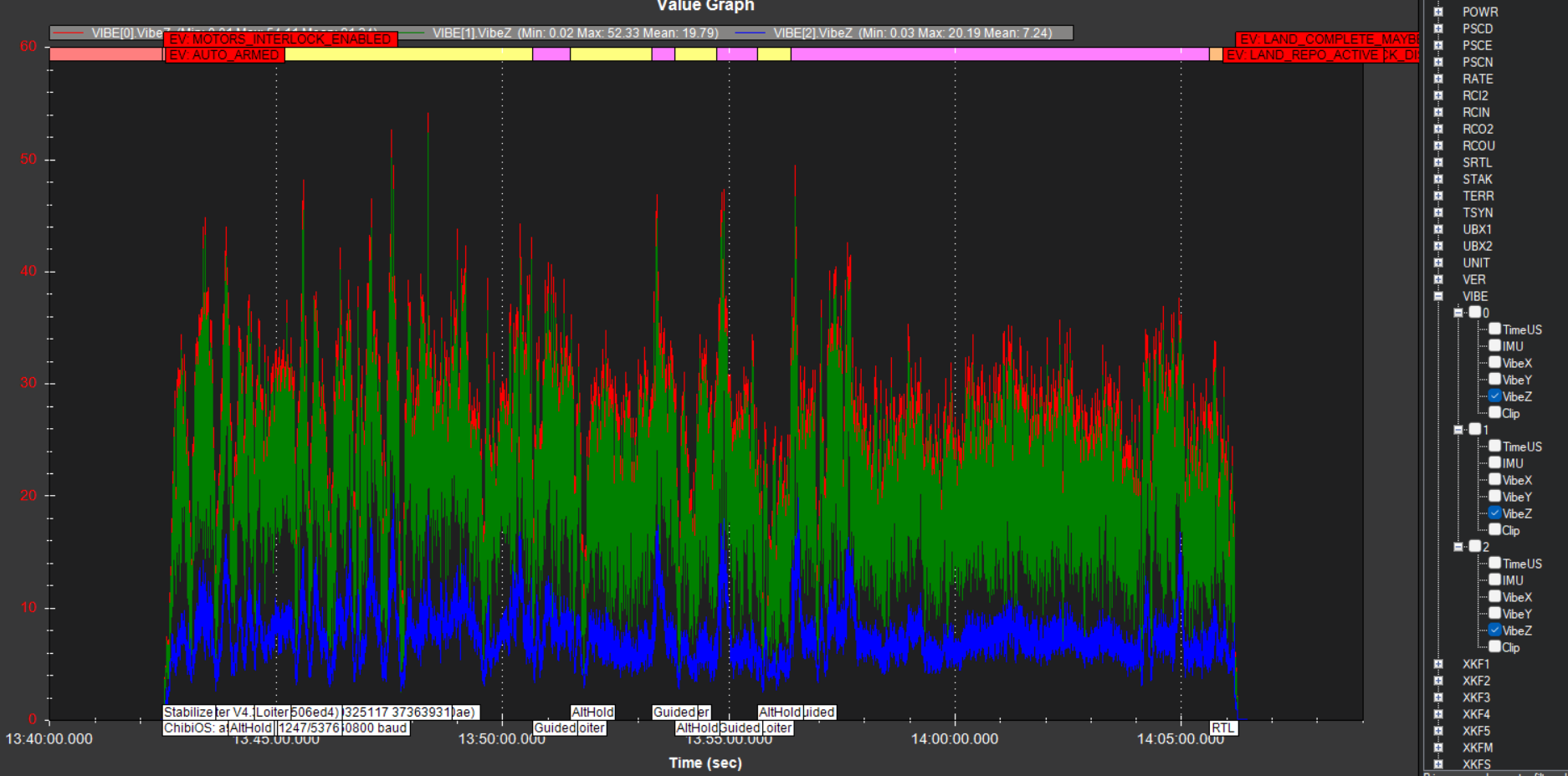
Here you can notice that still Non-Isolated IMU (IMU2) is very less vibration when compared other 2 IMUs.

I have configured the Notch filter too and attached logs with all Pre and Post filter Logs.
https://drive.google.com/drive/folders/1tPa-4MmT5pvLS-xJeIaOEmP6Dk8fIL3a?usp=sharing

1 Like

That looks good, I like how you’ve done the wiring.
Z axis vibrations are a bit high, but X and Y are good.
When the cover is on, is the GPS cable not causing a problem?? I’m just wondering what would be causing the high Z vibrations.
Does the cover vibrate where it attaches? or in between the attachment points?

You definitely should set these:
BATT_ARM_VOLT
BATT_CRT_VOLT
BATT_FS_CRT_ACT,1

For the harmonic notch filter, I would set:

INS_HNTCH_FREQ,30
INS_HNTCH_BW,10

and your other settings are good how they are.

If that introduces instability then change to these:

INS_HNTCH_FREQ,55
INS_HNTCH_BW,20
INS_HNTCH_HMNCS,1

All GPS cables are well within safe range of the canopy cover i don’t think cover would introduce this vibration.
next i will try with single layer of 3M tape for mounting 600mm Industrial Grade 3M VHB Tape (5952) at Rs 20400/roll in Bengaluru | ID: 15368102488
lets see how much it improves.

tuning and the way PID set are all ok?

from which log you have arrived the above graph ?
as of now i have set
INS_HNTH_FREQ = 45
INS_HNTCH_BW = 22

Try this. This has worked for me for bigger airframes with 60inch props.
image

Finally i have done it with the vibration arrest on cube orange + by mounting on above damping system.

here is the Each IMUs Vibe Vs Speed

we have flown at speed of 18m/s max to see the peaking vibration and its not increasing more than 20m/s/s on X and Y axis. Particularly well improvement on Z axis.

i have checked the Log Attitude graph for Roll, Pitch and Yaw and looking good but RATE graph roll &pitch look like need to be improve.


here is the Log file and @xfacta can you check my notch settings are correct?

1 Like

Vibrations look good.

You should DEFINITELY set these

BATT_ARM_VOLT
BATT_CRT_VOLT
BATT_FS_CRT_ACT,1

use the spreadsheet linked further back in this discussion, by selecting the number of cells and battery type to get the correct voltage values.

You could probably run Autotune with AUTOTUNE_AGGR,0.08 to get some good PIDs
If that produces PIDs that are too “loose” then use AUTOTUNE_AGGR,0.1

1 Like