CUAV Nano to 4-in-1 ESC

Hello, I am relatively new to autopilots and wanted to get some insight on my setup (I assembled and am in the testing stages now) to make sure its possible. Here is my GitHub repo link for reference, hope you like it!

Components:

  • CUAV V5 Nano (ArduCopter V4.4.4) using Mission Planner GCS
  • BLS 50A 4-in-1 ESC (BLHeli_S)
  • Raspberry Pi 4B (DroneKit & MAVLink)

I understand the connection between the Pi and CUAV is just UART. For the connection between the ESC and the CUAV I am confused how to wire it similar to this pixhawk-4-in-1-esc forum post. Here is the relevant information for my setup:
ESC:


CAUV V5 Nano

My Build:

My understanding is that I need to connect S1 to M1, …, S4 to M4. Regarding the other pins (TELEM, CURR, VBAT, GND), how does MissionPlanner allow me to run ESC calibration through ArduCopter running on the CUAV? Alternatively, I bought the ESC as a stack with the F405V3 FC that I can connect together and calibrate it with BetaFlight Configurator. This isn’t ideal since I have 2 FCs when I only need the CUAV, but it is possible.

Thank you in advance and I can’t wait to move past this road block :slight_smile:

First up you wont need to run ESC calibration. Use DSHOT600, it’s easy and way better than ordinary old PWM.

The real roadblock here is powering your flight controller - you need a BEC capable of 5.2v 3amps, or the power brick that came with it.
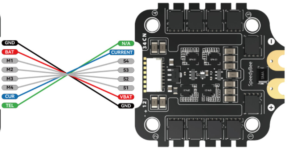
If you use a small separate BEC, the ESC can still provide the battery voltage and current data via it’s Curr wire and the Telem data. The alternative is to ignore the Curr wire and remove it from the connector housing

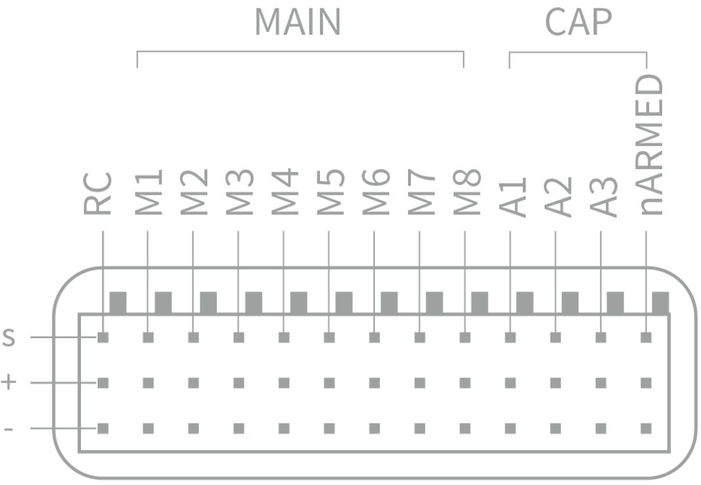
You are correct about the S1 → M1 relationship, connecting to the S pins
However on the CUAV V5 Nano I have here the M1 has never worked for DSHOT, so be prepared to bump all your connectors along one position. You might end up using M2 to M5, it’s no big deal and easy to adjust.
The GND wire should also connect to a - pin on the servo output pins.

The VBAT wire wont be used and should not be allowed near the flight controller :slight_smile: so you can either securely terminate it or remove it from the connector housing entirely. I would not even use this wire to run a BEC for supplying the V5 Nano, because the wire is usually incredibly thin and I wouldnt trust it to supply a couple of amps continuously.

The Curr wire is similar - you can go to the trouble of routing it to the V5 Nano Power input connector, and current data is nice to have, but not as essential as the battery voltage. I would tend to remove it from the connector housing too. We can live without the current data.

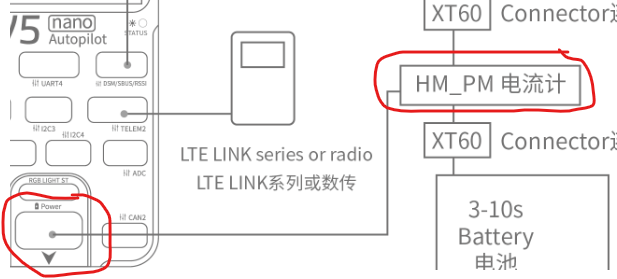
If you are NOT using the power brick that came with the V5 Nano, you’ll need to route a BEC +5.2v and ground wires to both of the appropriate pairs of inputs here too.
image

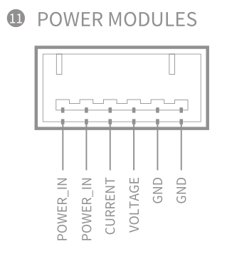
The Voltage and Current pins would remain unused.
If you are using the CUAV power brick, then there are no changes to make to it, except ALL current should flow through it - meaning it would have to be wired between the ESC and the battery. You might not have space for this.

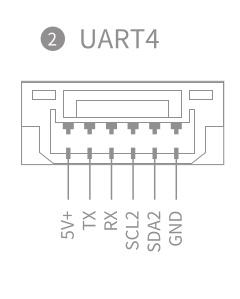
The Telem wire should be connected to UART4 RX input on the V5 Nano.
image

For Arducopter settings:

BATT_MONITOR,9        // use ESC telem data
BRD_SAFETY_DEFLT,0    // disble the safety switch
MOT_PWM_TYPE,6        // set DSHOT600
SERIAL4_BAUD,115      // set up UART4 for the telem data
SERIAL4_OPTIONS,16
SERIAL4_PROTOCOL,16
SERVO_BLH_AUTO,1      // you dont need anymore servo settings than what is listed here
SERVO_BLH_RVMASK,*    // useful later for reversing motors, it is a bitmask
SERVO_DSHOT_ESC,2

and after a reboot you should have passthrough working, although you probably wont need to change any BLHELI settings at all.
You can choose whether to reverse a motor in the BLHELI_S configuration app, or with the SERVO_BLH_RVMASK in arducopter settings (this works for BLHELI32, unsure about BLHELI_S)

In the MissionPlanner messages tab you should see something like:
RCOut: DS600:1-8 PWM:9-14
indicating DSHOT600 will be used for some V5 Nano outputs.

Extensive use of the MissionPlanner motor test section is highly recommended. The motor “numbering” changes to motor “lettering” in the motor test section.
Try setting your frame type to BetaFlightX and reboot, the motor order may be correct.
FRAME_TYPE,12
When you select the test “All in Sequence” you should see motors activate in A , B , C , D order.

image

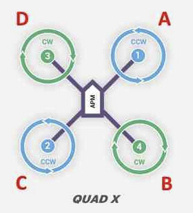
Be sure to get all the clockwise / counter-clockwise spin direction correct.

In your github it specifies a 6S Lipo, put in these settings:

BATT_ARM_VOLT,22.1
BATT_CRT_VOLT,21
BATT_FS_CRT_ACT,1
BATT_FS_LOW_ACT,2
BATT_LOW_VOLT,21.6

Dont think you can ignore them “just for testing” or any other reason.

Yell out if you run into any issues.

1 Like

Hey, thank you so much for the detailed answer. Can you please clarify why I will not need to do ESC calibration? This seems counterintuitive to me.

I want to clarify a few things since you gave me multiple options (greatly appreciated).

  • I have a DC-DC Buck converter which I run at 5.1v to power my Pi, and Oak-D Lite camera.
  • For the CUAV I am using the HM_PM harness to power connector.
    image

Thank you so much for the configuration settings as well which is incredibly helpful. I will hopefully have all this together in about 1 month time to be able to give an update!

Cheers,

I just noticed the blurb for your ESC says “ESC Telemetry: Not supported” so that could be a real bummer. I would persist with the physical connections and even the related Arducopter settings (serial4) in case it works with Bluejay firmware (see below). Maybe if that ESC fails one day, and we hope it doesnt, then another ESC will be a drop-in replacement with the telem wire already in place.

The alternative is to use bidirectional DSHOT, which is supported on the flight controller and by the Bluejay firmware - this gives RPM data back to the flight controller, which is very useful and much better than having nothing. Bidirectional DSHOT is nothing to do with reversible motors or 3D flying, those are different features. The bidirectional DSHOT firmware for V5 Nano is just the same as loading the ordinary firmware and should be in the list when you go to install or upgrade firmware. There’s no noticeable difference except for setting this parameter (in addition to the others I already specified)
SERVO_BLH_BDMASK,15

The “calibration” procedure was to align the two different PWM systems of the flight controller (or receiver) and the ESC. This is because PWM is an analog signal dependant on the clock frequency of each device, with no guarantee of a matching baseline. 1500 PWM from the flight controller could mean about 1600 to one ESC and 1400 to another, since their clock frequencies could all be different. Being analog the PWM signal is also subject to interference and travels poorly over long wires (despite all those aileron servos hanging off three feet of wire).
Be aware that when PWM is mentioned in relation to these modern ESCs it is most often about the internal signal that drives the MOSFETs and turns the motors, not the old fashioned external RC PWM.
DSHOT it is a digital serial protocol with error checking, and the flight controller demands a specific output from the ESC, regardless of mismatched clock frequencies. No such calibration is required.
If you do perform the calibration, it only applies to a PWM input signal and the ESC (BLHELI) completely ignores that when using DSHOT anyway.

Excellent - that takes some extra work out of the equation. OK to ignore (and remove) the current wire from the ESC. You will only need the GND, Telem and motor/signal wires.
Use the BATT parameters for the CUAV power module, and you can sett BATT2 for ESC voltage if you like, BATT2_MONITOR,9 , but it wont be critical. The ESC voltage, RPM and similar will all still be captured in the log if they are needed for any diagnosis.

I dont have any BLHELI_S ESCs myself, so suspect you might need to change the firmware to Bluejay to get a few more features and current updates.
BLHELI_S and Bluejay are for ESCs with a small somewhat limited processor, so inevitably you miss out on something that BLHELI32 ESCs can do better,faster or more of.

2 Likes

Oh, and whether you get the telemetry wire going or use bidirectional DSHOT (or both!) then these settings give you a working Harmonic Notch filter with no further config necessary:

INS_HNTCH_ENABLE,1   // write then refresh params to see the rest
INS_HNTCH_BW,20
INS_HNTCH_FM_RAT,1
INS_HNTCH_FREQ,80
INS_HNTCH_HMNCS,3
INS_HNTCH_MODE,3
INS_HNTCH_OPTS,2
INS_HNTCH_REF,1
INS_LOG_BAT_MASK,1   // logging to check it's all working
INS_LOG_BAT_OPT,4
1 Like

Thank you very much for the support. I actually shorted my BLS 50A so I ordered the BL32 50A ESC which has the 32-bit processor and flashing BlueJay shouldn’t be needed although I saw a lot of hype for that firmware. I checked and the ESCs are an inplace replacement and I can get my project moving along!

Thank you for investing in my project,
Cheers

Yes - the Bluejay firmware only applies to BLHELI_S ESCs.
BLHELI32 is good to go.
Use all defaults except for:

  • Low RPM Power Protect = OFF (there is an Auto setting now, use that if you have it)
  • Low Voltage Protection = OFF (rely on the flight controller battery settings)
  • Temperature Protection = 90
  • Motor Timing = Auto
2 Likes