Hi,
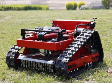
I’m looking for a convenient solution for creating missions for my lawn mower. It’s a skid-steer, track based and quite heavy vehicle and the issue is that where it performs pivot turns or tight curves you won’t have to mow the lawn for a while anyway. Because it will somehow plow that area with its tracks like a small tank
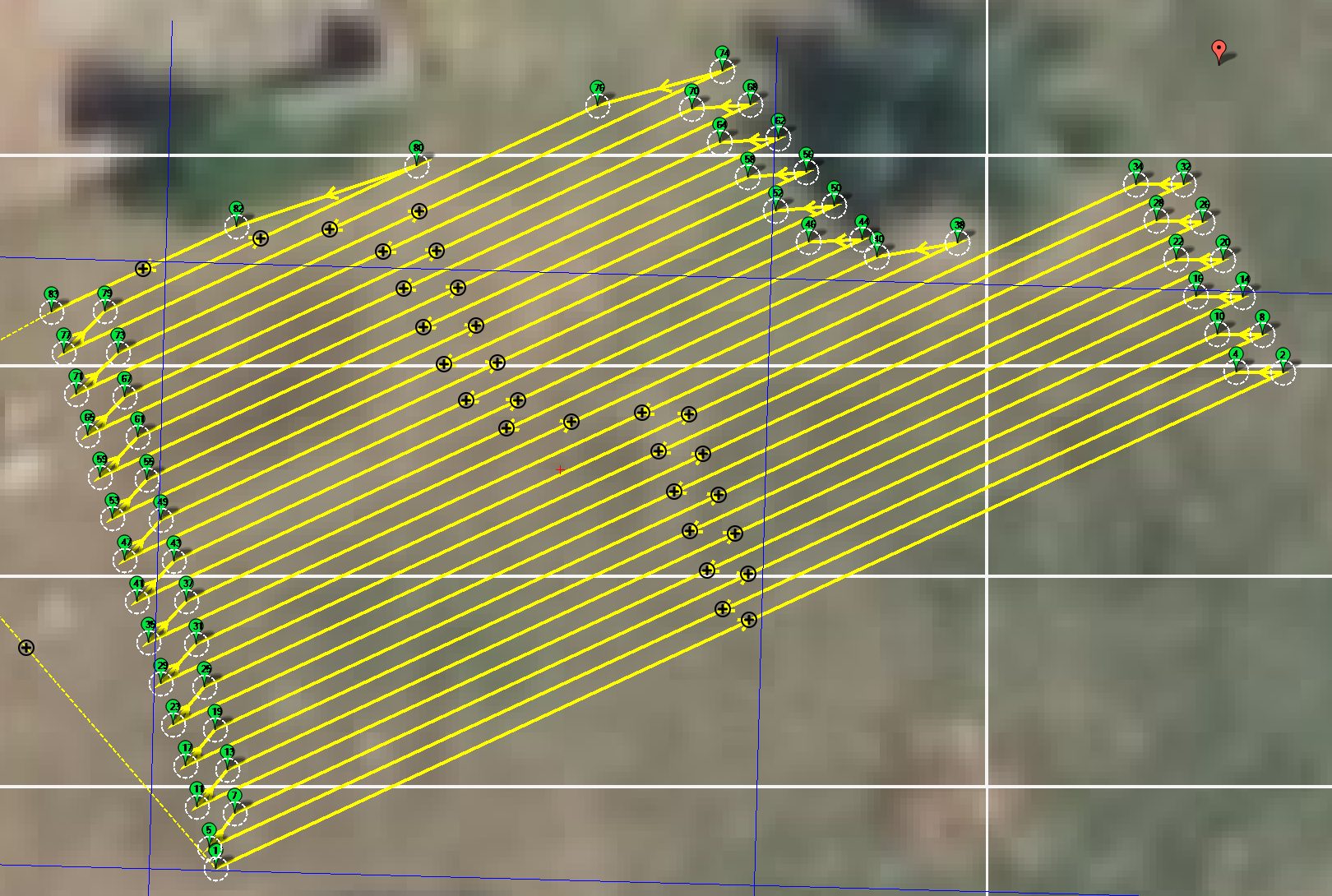
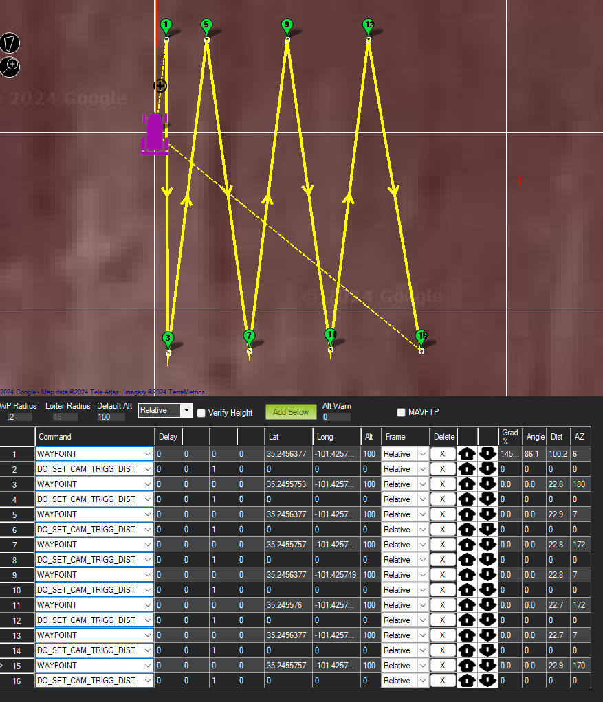
So when controlling it manually, usually my pattern is to go back and forth (reversing at each end) and “changing lanes” with as little steering as possible, like so:
This is a mission I created manually in large parts using Excel and I’m looking for a way to automate this more. Ideally having to draw a polygon and with the possibility to add inner exclusion zones (mostly for trees, i.e. round).
I guess there is no ready solution for that, but maybe something to start with…? Thanks for any ideas!
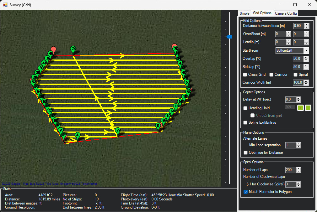
They are ~90 degree corners in most places, though, and you cannot specify exclusion zones, though you can enable obstacle avoidance and put fences around fixed objects.
Yes thanks, I’ve been there, but that’s what results in quite f… let’s say messed up edges due to the ~90° turns, especially on humid soil (it’s hilly with lots of clay here).
So I literally need to reverse using DO_SET_REVERSE each time it hits the polygon or an obstacle, so to avoid as much steering or pivots as possible.
If there is nothing on this yet, I’ll try my hand at it these days…
Great content you created there, I have seen that already some time ago with interest. And I totally agree with the spiral path for your mower and surface type.
But spiral isn’t a good choice in my case because:
Perimeter around the house/garage already has many angles
Many obstacles like trees
Terrain is hilly - you don’t want the rover to go sideways
…and the tracks do really dig stuff up as soon as you start to turn >30°
This type of mower requires another pattern, at least for my use case.
Following this. We are using a similar mower design. Turning 90 or 180 takes a while and makes a mess. Backwards and fowards is way more time efficient.
I like your excel approach, i’ll do the same once we get a couple of other kinks out.
At least figure a generic way to build some back n forwards path, and coding skills aside - doing a Yuri and merge it into MP.
Yes, exactly. I’ve got some ideas in my head already for an algorithm to create such a pattern. I’ll try to put that into code when I find some time (will be C# probably, that’s my daily business anyway), and if it works then we could create a suggestion to adapt and merge it into MP.
I know it’s been a while since you posted this, but when I was deciding on the mower I wanted, tracked vs wheeled, which one would tear up my lawn the least was at the top of my list of deciding factors.
I’m just in the planning stage, but one of the things I plan on testing/tweaking is turning radius. I do have experience with tracked combat vehicles, and if you can avoid fully braking either track, it 1. does less damage to the turf, and 2. decreases the likelihood of a thrown track.
I know that turning tightly is ideal for planning a mowing mission, since your cutting paths are right next to each other, but you might be better off making the turning radius a little less than the width of your vehicle. This would force you to run two missions since you would be skipping a row of grass each time, but with RTK you should have no problem hitting the grass you missed on the second run.
I am glad to learn that my use case is already of interest to others. I’ve attached a one-minute video of my little mower doing a grid mission with reversing back and forth, long before I learned about Ardurover and RTK. It has sodar for navigation and runs a grid made up from a pre-existing table of x-y values. Alternatively, you can generate a raster by specifying the diagonal corners of a rectangle. I recently added a layer of hardware to switch over from sodar to RTK for the precision it offers.
My interest now is to learn how to instruct MP to simply follow a pre-made grid with reversals, but no pivot turns. (And, maybe a few K-turns in spots.) Since my lawn is not a moving target, the flexibility of doing surveys on the fly is way overkill. Could someone kindly point me to any docs that can get me going in that direction?
Mission Planner doesn’t support auto generation of paths with reversals like your video shows, nor any type of 3-point turn geometry. Sustained forward motion is pretty much assumed. There may be a fairly easy way to achieve the type of raster pattern you desire with a little manual manipulation.
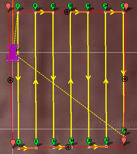
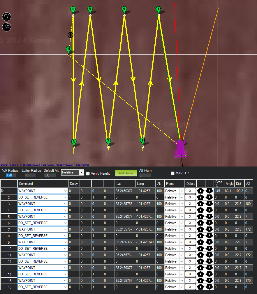
Change each instance of DO_SET_CAM_TRIGG_DIST to DO_SET_REVERSE, and alternate setting the first parameter between 0 and 1 (a 1 in that first field is the reverse navigation trigger, and 0 cancels it):
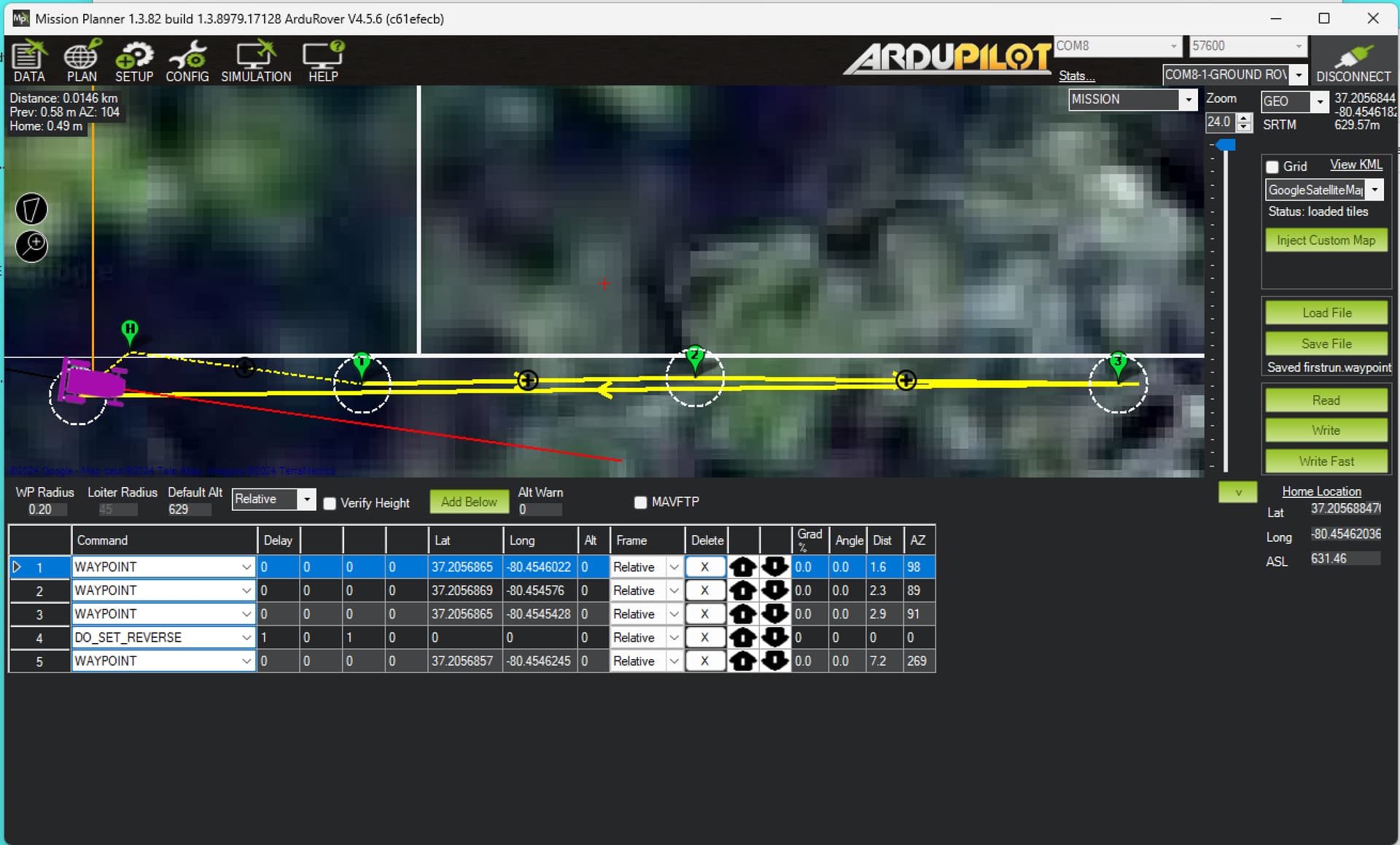
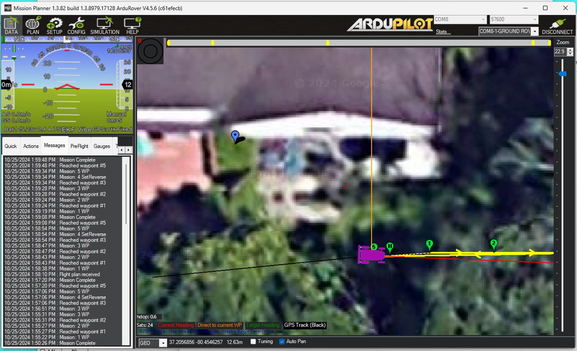
My little mower can now traverse back and forth patterns, thanks to Yuri’s example (sample screenshots below). It shows “GPS:rtk Fixed” on the HUD, but can only get about 0.5 m accuracy. Can this be due to the default setup on the RTK page which surveys the base station (an F9P) to 2.0 m? (Takes about 3 minutes.) Or are other steps required?
Are you after relative precision (minimizing crosstrack error) or absolute accuracy (real world accuracy with respect to the WGS84 reference frame)?
If crosstrack error (deviations from the path) is problematic, then you must tune your vehicle better.
If you want absolute accuracy, a self-surveyed location won’t do. Even when self-survey precision (which is essentially just std dev of observations) is reported at sub-cm level, the actual survey results are probably only good to 1 to 1.5 meters in practice. To tighten that, you should get a professional surveyor to provide the location of your base antenna, use a known good local NTRIP source for correction of your fixed base location, or post-process a several hours long observation (which is a complex subject that I have captured briefly on a project of my own).
The good news is that you generally don’t need to get pinpoint accuracy out of your fixed base. So long as you use the same survey location for every session (i.e., save the settings after one survey-in, and do not subsequently re-accomplish the survey-in step), you’ll always get the same relative offset from real-world location, and your missions will be repeatable to a high degree of precision.
More good news - there’s a CORS site that’s very close to you on VT Montgomery Airport. If publicly available as an NTRIP site (unlikely based on a brief search of my own), you can skip use of the fixed base entirely. Otherwise, it would be an excellent source of post-processing data (which you can get historically, even if the site does not publish live).
Dr Bob, our F9P xtrack error is +/- 0.05 ie 50mm (or 2 inch things?) and spends most of its time +/- 0.03 or less. Repeat mows are usually within the wheel tracks of the previous. xtrack errors are repeatable also, ie wobbles from previous mow are in the same place - so environmental.
Per Yuri, go run the tuning process and see if your desired path and actual path align. PID tuning is the difference for achieving the mowers goals or wombling around.
RTK accuracy deceases with distance to base station, so check that. If your base station is close but poorly surveyed, then you would see low xtrack errors , high consistency, but poor absolute positioning (a bit like google maps not aligning)
Yuri/Bob - I ran the forward/reverse pattern on our mower - massively quicker. A jagged edge of grass left, but easily sorted with a couple of outside loops.
Each strip end has gone from stop/turn/go/stop/turn/go to a flowing bend/reverse. Way less lawn ripping and giant squid sucker marks along the lawns edge where the mower rotates and rips.
All tuned-up and getting just noticeable driving errors. I’ve attached a BASIC program that creates a rectangular grid as a text file for Mission Planner. It’s scaled for my latitude of 37.2057, where a unit in the 7th decimal place = .3484 inches. RASTER.txt (1.7 KB)