Introduction
This guide will walk you through to create a simulation model for Ardupilot with RealFlight as the simulation engine. As an example, a VTOL aircraft will be modelled, but it is applicable to an airplane and multicopter form factor as well.
It covers the following topics:
- Preparing 3D model parts for their specific functionality.
- Creating a texture file to accompany the model.
- Exporting the 3D file into a format suitable for RealFlight to read.
- Importing the model into RealFlight and configuring it to work with Ardupilot SITL.
This guide will not cover any 3D CAD modelling techniques nor Blender use. You will need to obtain some knowledge on using Blender on your own. The net is full to the brim with tutorials and documentation.
Software of choice
RealFlight has arguably been the most impressive simulation engine of recent for Ardupilot’s Software In The Loop (SITL).
Sure the default, embedded SITL backend is the quickest and simplest one to get you started, but it lacks detailed physics and a visual aspect. JSBSim and FlightGear have fallen out of favour and frankly were hard to set up anything other than a large airplane with. Gazebo isn’t great with anything relying on detailed aerodynamics and AirSim never really caught on. Webots might get more traction now that it’s open-source, but likely won’t focus on airplanes either. And until I revive last_letter from the dead, that’s not a solution either.
RealFlight brings the best combination of nice graphics, aerodynamic fidelity and customizable aircraft to date. But it does come with a hurdle: It’s really hard to create a new aircraft model for it and it requires 3rd party tools. At least for me, it was the program with the hardest learning curve out of the lot.
The most prominent workflow goes through 3DSMax, to design (or at least convert) the 3D model. However that’s available only for Windows and I prefer to stay within the Ubuntu ecosystem as much as possible. Also 3DSMax costs money (unless you’re a student) and I prefer free stuff as well.
So, this guide will use exclusively [Blender](https://www.blender.org/! I’ve noticed that Blender 4 sometimes crashes on me and it might have something to do with my graphics card. Blender 3 will work just as well for this guide.
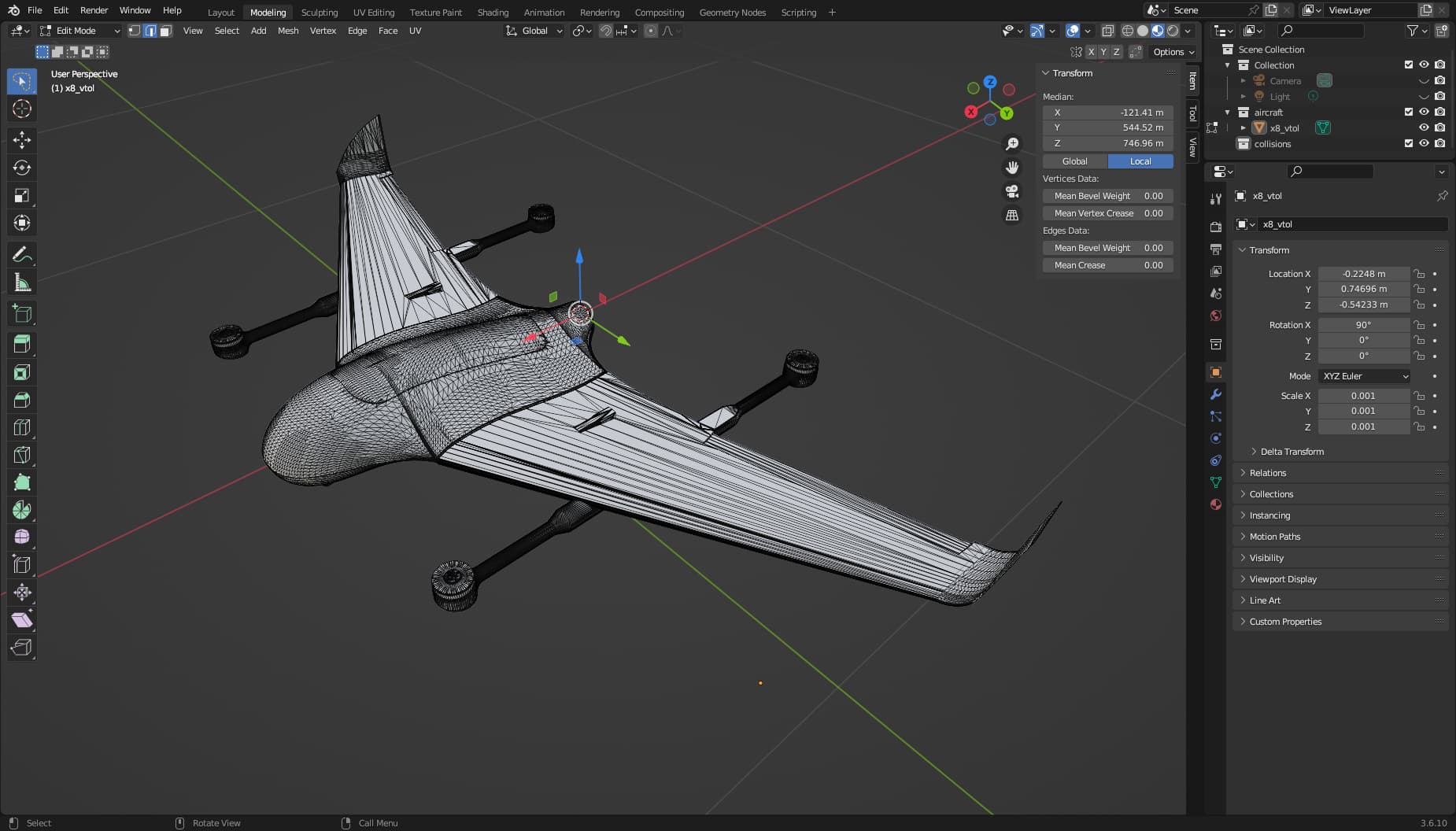
Mesh import
Assuming the 3D model is available, we import it in Blender. Typically this will be in the form of an .STL file.
Unfortunately, Blender can’t import a .STEP file. This is a file format with much cleaner and lightweight representation. It doesn’t exclusively use triangles to represent surfaces, unlike .STL, and I hear modelling stuff with triangles in Blender is a big no-no. Discord user Isso has suggested CAD Exchanger Lab as a tool to convert from .STEP to .FBX, but I couldn’t even get a price tag for that software. And when you have to ask for the price…
The way I have set up blender is to use Metric units for my project and model the aircraft in a 1:1 scale.
So, if you have imported an .STL file, the first step is to simplify the mesh. One way to do it is by selecting the faces in Edit mode and using Limited Dissolve.
Reducing the face count will help RealFlight a lot in calculating the visuals and let it run in higher FPS. This is especially useful for round parts, like wheels.
Having a total part count of a few thousand faces is a good ball-park goal, but naturally the fewer the better.

A drawback of this procedure is that some meshes may get badly mashed, losing some visual fidelity.
Although not necessary, it is recommended to align your aircraft axes in Blender with the RealFlight convention, to save yourself from conversion mistakes later:
- Y-Axis: Forward
- X-Axis: Towards the right
- Z-Axis: Upwards
Part splitting
Now, the model needs to be cut up in separate parts (objects, as Blender calls them), one for each notional moving or detachable part, so that RealFlight can identify them in its Aircraft Editor and animate them separately.
Examples that you will want to split into individual parts are:
- Fuselage
- Wings
- Control surfaces
- Booms
- Multicopter motor mounts
- Motor rotors (bells)
- Landing gear
- Springy sections of landing gear
- Wheels
- Retracts
- Gear doors
Specifically for the propeller part, its shape is not important, as it will be replaced by RealFlight in-game. Modeling it as a placeholder ring is typical.

If your model has multicopter motors, it is important to designate a separate part between the boom and the rotor/spinner. That will act as a “motor mount” and is necessary for the correct modelling in RealFlight.
This is a good point to make sure the face normals of your parts are all pointing towards the correct direction.
This is an exmaple of badly-oriented normals.
Parts naming
In one of the most cryptic aspects of RealFlight, the parts you create in Blender need to be named with a specific pattern to be recognized as usable meshes, but the rules aren’t precisely known.
For sure, they need to start with ~CS [^RFpartnames]. Some parts need to have a specific name, but it’s not clear to me which ones.
In other cases, the parts need to have the same suffix for RealFlight to automatically associate them, for example the motor and the spinner.
But in general I’ve also found that most any name following the pattern ~CS_<partname> is usable within RealFlight.
In any case, the following table hopefully provides good choices for part names[1].
| Part | Part name | Comment |
|---|---|---|
| Fuselage | FUSELAGE | The main, root mesh. |
| Right main wing | ~CS_RMW | |
| Right main aileron | ~CS_RMA | |
| Right inner flap | ~CS_RMF1 | |
| Right outer flap | ~CS_RMF2 | |
| Left main wing | ~CS_LMW | |
| Left main aileron | ~CS_LMA | |
| Left inner flap | ~CS_LMF1 | |
| Left outer flap | ~CS_LMF2 | |
| Right bottom wing | ~CS_RBW | |
| Right bottom aileron | ~CS_RBA | |
| Right upper wing | ~CS_RTW | |
| Right upper aileron | ~CS_RTA | |
| Left bottom wing | ~CS_RBW | |
| Left bottom aileron | ~CS_RBA | |
| Left upper wing | ~CS_RTW | |
| Left upper aileron | ~CS_RTA | |
| Right horizontal stabilizer | ~CS_RMHS | |
| Right elevator | ~CS_RME | |
| Left horizontal stabilizer | ~CS_LMHS | |
| Left elevator | ~CS_LME | |
| Main vertical stabilizer | ~CS_MMVS | |
| Main rudder | ~CS_MMR | |
| Right vertical stabilizer | ~CS_RMVS | |
| Main rudder | ~CS_RMR | |
| Main vertical stabilizer | ~CS_LMVS | |
| Main rudder | ~CS_LMR | |
| Right main landing gear | ~CS_RG | |
| Right main wheel | ~CS_RW | |
| Left main landing gear | ~CS_LG | |
| Left main wheel | ~CS_LW | |
| Steering gear | ~CS_SG | |
| Steering wheel | ~CS_SW | |
| Taildragger spring | ~CS_SG_SPRING | If used, this is meant to be the parent of ~CS_SG. |
| Propeller | ~CS_ENGINE_suffix | This defines the propeller position. Suffix multiple instances. The mesh can be anything, e.g. a ring. Actual propeller model will be filled in by RealFlight. The engine visual model itself can be part of the fuselage. |
| Spinner | ~CS_SPINNER_suffix | Suffix needs to be the same as the corresponding propeller. |
See reference [2] for modeling examples and name usage.
Not all parts are mandatory and not all parts are written down on the list. Adapt to your aircraft design.
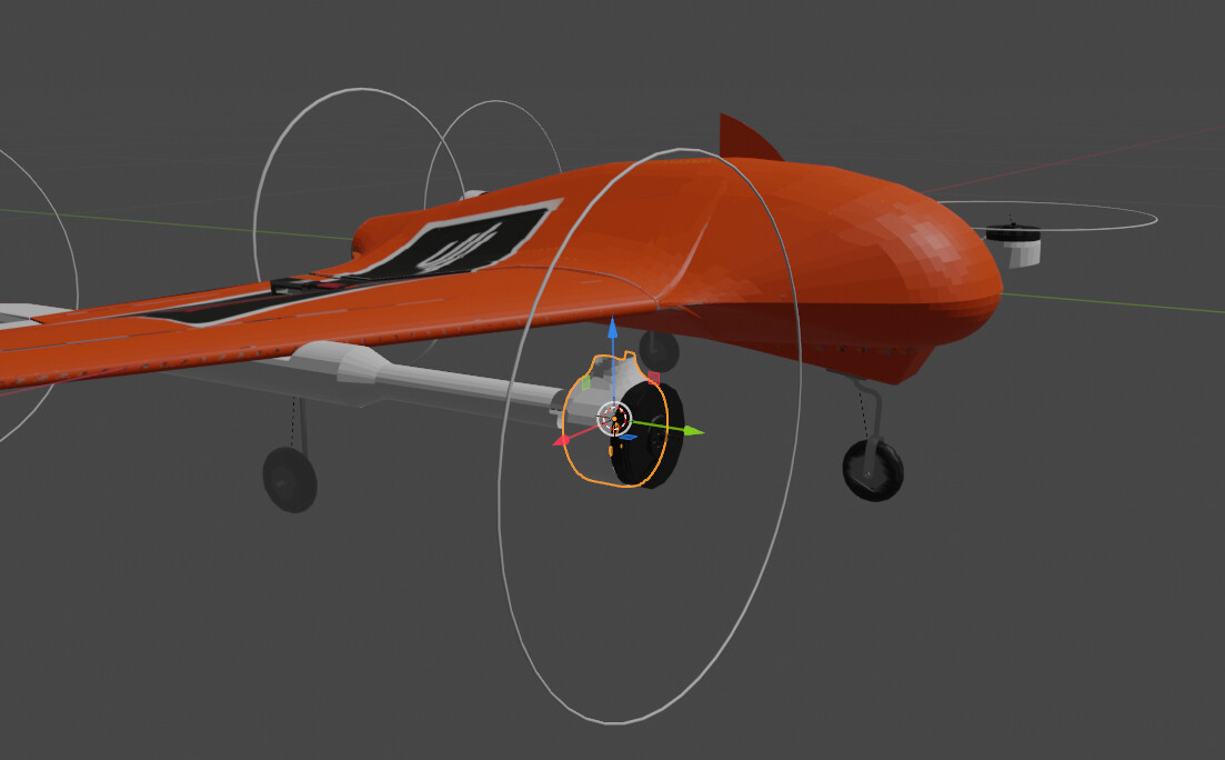
Part local axes (pivots)
The object pivots are important for the correct modelling of the aircraft in RealFlight.
In Blender the X-axis is red, the Y-axis is green and the Z-axis is blue.

Fuselage
The fuselage (and hence the whole aircraft) should follow a right-hand axes system where:
- The aircraft front points towards the Blender +Y axis.
- The right wing must extend to wards the +X axis.
Move the fuselage pivot so that it lies approximately on the Center of Mass of the aircraft. Move the fuselage so that its origin also coincides with the World Origin. It is possible to tweak the location of the CoM in RealFlight, but also part changes in the model within RealFlight will change the CoM.
For most other objects, their pivots should be setup at the center of the object in the same orientation as the fuselage.
However, there are many exceptions for:
- Control surfaces (ailerons, elevators, rudders, flaps)
- Wheels
- Retractable landing gear
- Engines
- Spinners
- Gear doors
where their pivot frame (local origin and axes of the part) are important.
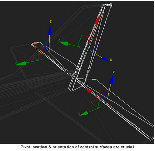
Control Surfaces
Origin: Coincident with the hinge line. Its position along the hinge line isn’t important.
X-axis: Collinear with the hinge line, denotes the axis of rotation.
For rudder, +X points up.
For control surfaces meant to be controlled by the same channel (e.g. ailerons) their X-Axes must point towards the same general direction for the control surfaces direction to agree.

Airplane Engines and spinners
Origin: At the center of the propeller.
Y-axis: Towards the thrust direction.
X-axis: Towards the right.
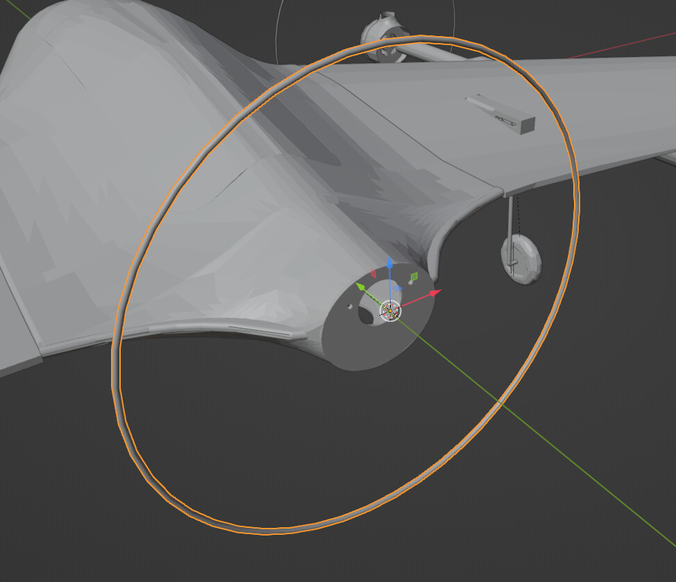
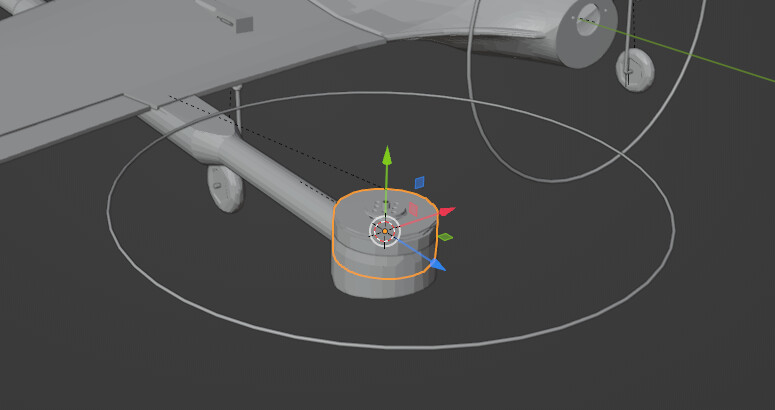
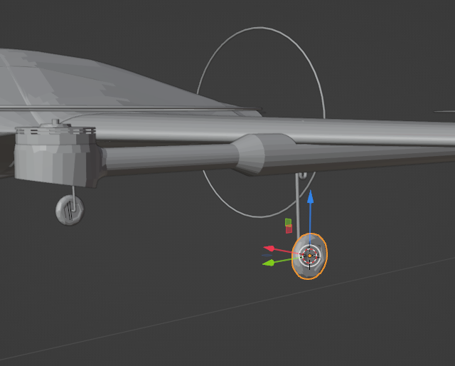
Multicopter thrusters
The spinner and the propeller axes are as follows:
Origin: At the part center
Y-axis: In the direction of thrust
X-axis: Towards the right.
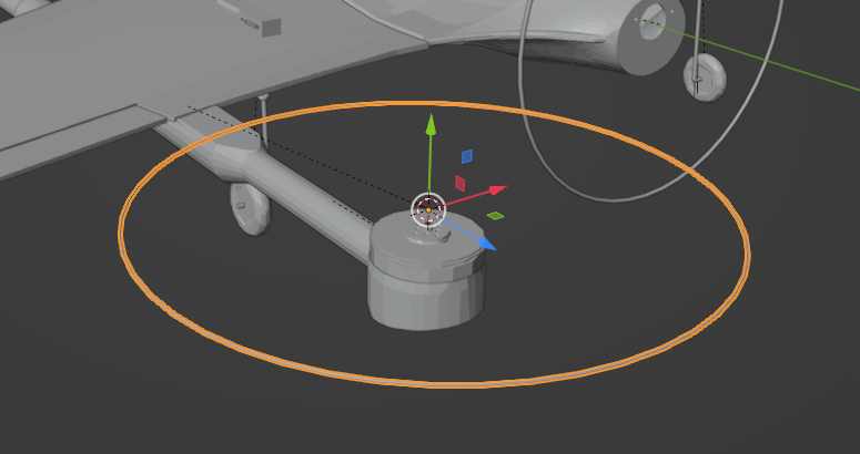
Steering Gear
Origin: Center of axis.
Z-axis: Along steering axis.
Y-axis: Towards the front.

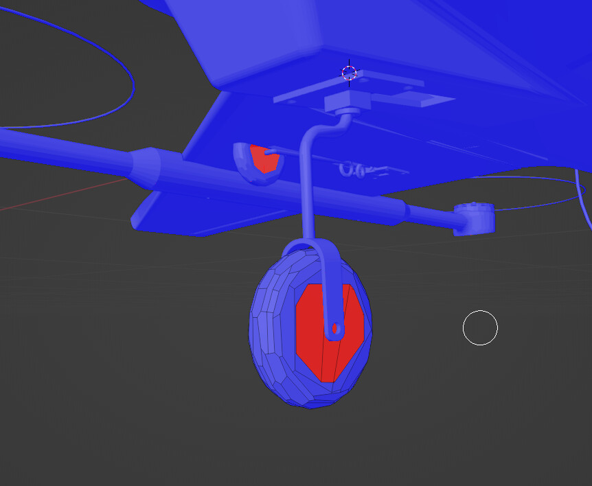
Wheels
Origin: Center of wheel.
X-axis: On the wheel axis of rotation
Y-axis: Towards the front.
Collision meshes
Each part needs to also be assigned a collision mesh. This is the geometry that can snag on trees and clips on flagpoles. RealFlight will use it to calculate those collisions. It’s a good idea for this geometry to be as simple as possible, because calculating collisions is one of the hardest things for a simulator to do. If no collision meshes are defined, then the visual meshes will be used for collision too.
Every collision mesh name starts with ~CS_COLL. If at least one collision mesh exists, then all visual meshes will be ignored for collision calculations.
Not all parts of the mesh need a collision mesh. For example, the ~CS_ENGINE component describes the location of the propellers. The mesh is just a place holder and does not provide any information about collisions and therefor does not need to have a collision mesh. Also, if the vehicle contains inner details like cockpit/pilot figures, those do not need any collision meshes since an outside surface will encompass that surface.
The collision meshes should follow these guidelines:
- Make sure the collision mesh is a child of its respective graphical mesh.
- Make sure that the collision mesh encompasses the graphical mesh.
- Make sure it’s as low poly as possible (below 1500 polygons for the whole vehicle). They don’t have to be very accurate.
- Make sure the collision mesh is closed (has no holes).
- Collision meshes for floats: Make sure the collision mesh closely follows the immersed portion of the graphics frame, especially if there is a “step”.
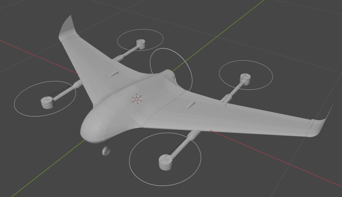
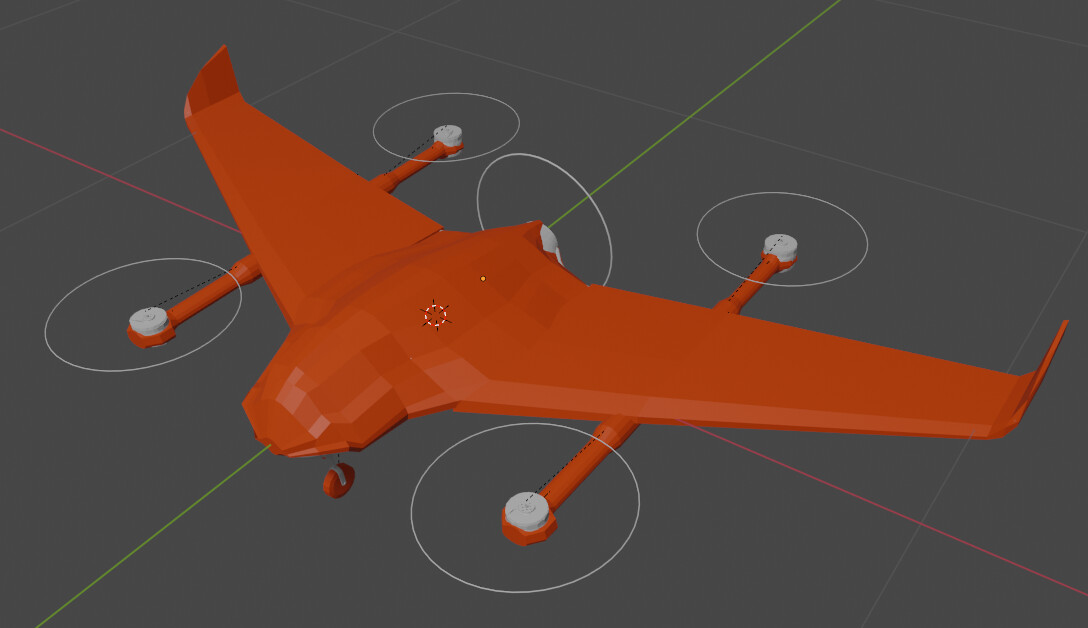
The following pictures show the plain aircraft and the same view with the collision meshes visible
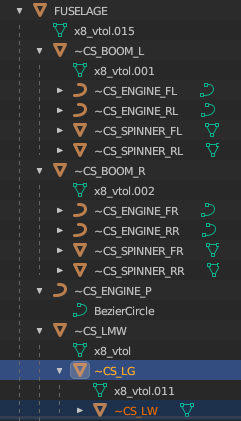
Model parts hierarchy
As in Blender, so in RealFlight, the aircraft parts have a hierarchy. Some parts are “parents” and others are their “children”. This mechanism allows parts to correctly move and break-apart.
Let’s assume we have a plane that has landing gears attached directly to the wings. When the wing is broken off, the landing gear will be broken off along with its parented wing. Equivalently, when the landing gear retracts, we want the 3D model of its child wheel to retract with it.
The fuselage is always the “root” (i.e. topmost parent) of the model. Typically a wing is the child of the fuselage and a control surface is the child of the wing. The collision meshes are children of their corresponding parts.
When assigning a parent, it is recommended to select the Keep Transform option for assigning a parent.
Here is an example of an object hierarchy structure.
Materials
Materials can be assigned to parts, to modify their looks. There are no limits to the amount of materials a model can have and they are independent of the texture file.
Materials are a good choice when you want to apply a uniform appearance to a part. You can have a material define the appearance of an object without needing to draw a texture for it.

UV unwrapping
A texture file accompanying the 3D model is required by RealFlight, even if it’s empty. This texture file maps the graphics and appearance of he 3D aircraft into a 2D image that is “wrapped” around the aircraft, applying colours and logos.
Thus, the first step is to “unwrap” any surface that is to be painted into an image.
Create a new 32-bit image file from within Blender to act as your texture and name it the same as your project file. Make the image dimensions large-ish, like 2048x2048 (or even 4096x4096 if you need the resolution). In any case, the image dimensions should be powers of 2.
It is a good idea to generate a new image using the UV Grid type. This will make inspecting correct texture application easier.
Save it as .tga (Targa).
Only one texture file can accompany the model.
It is possible to automatically unwrap every edge with the Smart UV Project function, but it’s strongly recommended to unwrap the faces manually. The texture image will be a lot more meaningful then.
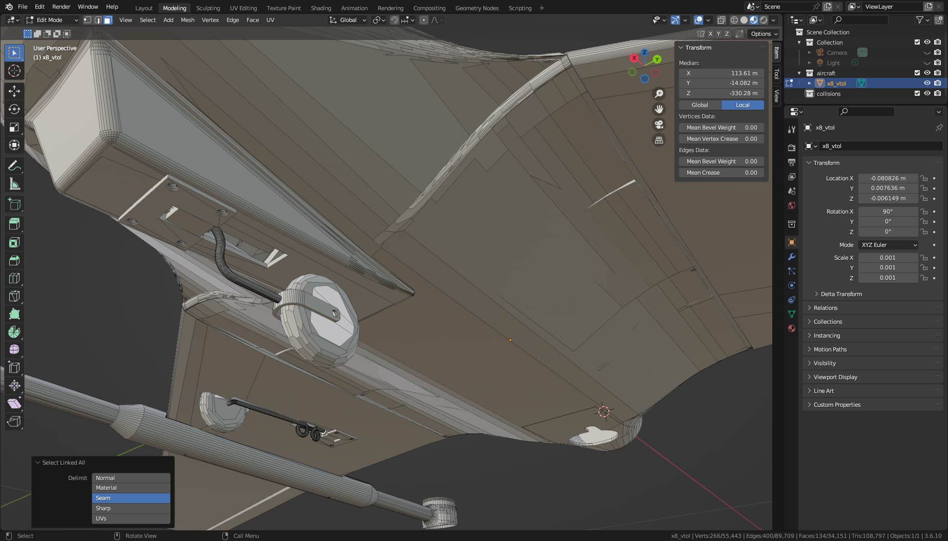
A core concept for unwrapping the surface of an object are the Seam Edges. These are the edges that will be “cut”, so that the surface can unwrap into a flat plane.
For each object, go to Edit Mode and select the edges that will be cut.
Invoke Edge Specials (Ctrl+E) and mark them as Seams. They will be marked with a different colour.

Invoke the UV Calculation menu (U) and pick Unwrap. This will create new projections for the faces onto the texture image.
Project from View is another useful option. It will map the surfaces onto the texture image neatly according to the current view projection, but it will lose resolution as the 3D object curves away from view.
The faces might not be to scale and it’s not mandatory. Arrange the faces on the image yourself, so that faces that need more detail occupy more space on the image. In any case, moving and scaling the faces around the texture image does not affect the 3D model.

Texture painting
Now that the faces have been unwrapped onto the texture image, the image can be used as a material to paint the 3D model.
Create a new material that will act as your texture material. As its Base Color select Image Texture and then select the texture image you created. Use that texture on any or all objects on your 3D model.
To see the applied texture, go to the Material Preview view type.
It is possible to use the Texture Paint workspace to paint directly in Blender, or apply a “sticker/livery” on the 3D model directly.


Alternatively, you can open the texture image in a 3rd party image manipulation software and edit it there. If you edit it in Gimp, remember to smash all the layers before exporting it anew.
Multicopter motors rotation
Now for the counter-intuitive part. For some reason, RealFlight expects all of its rotors to be facing with their local Y-axis forwards and X-axis to the right, upon loading the model.
However, our model contains multicopter motors. These will need to be rotated by 90 degrees along with their spinners and mounts and will be fixed later in RealFlight.
Blender export
Now it is the final straight to export the model from Blender into an .FBX file that RealFlight can import.
First, select all your objects and Apply the Scale operation. Do not apply the Rotation operation, as it will reset the local axes.
Blender can export to .FBX directly. If you have set your project units to Metric, you will probably have to scale it by 1/2.54=0.394 to size it correctly.
I believe that the rest of the transform settings do not affect the result.
Discord user isso has suggested using a plugin to manage the exporting and correctly encode some other custom properties, but I haven’t managed to make it work for me.
RealFlight import
It is now time to import the 3D CAD model and its texture into RealFlight.
Open RealFlight and import a 3D model. Point to the .FBX file and chose to import it as an Airplane or Drone, depending on what you have built.
So far I have used airplanes as a basis to build VTOL planes, but starting with a drone is probably also possible.
RealFlight will now ask you to select an existing model to act as a basis that you can edit, as it is impossible to create a new aircraft from zero.
It is strongly recommended that you do not use a complex aircraft as a basis. I have had severe issues with RealFlight crashing upon trying to delete extraneous parts while building models.
Instead, start with as simple an aircraft as possible and try to build up to your model.
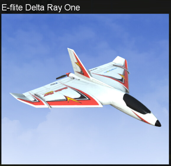
For VTOL delta wings, I like the E-flite Delta Ray One.
Finish the import wizard and you should get a message that the import was successful.
Editing the aircraft
This is the final stretch. But at least in my system the most treacherous. RealFlight is prone to crashes on my system when the Aircraft Editor is open. Save your work often and make sure it is actually saved, by reopening your model.
Open the Aircraft Editor and open the new aircraft.
Radio configuration
Go to the Radio tab and add as many Output Channels as your model will need. These are essentially all of the SERVO* output channels that Ardupilot will control.
Edit each channel so that Low Rates and Exponential are never active and the Input goes up to 100%.
You can temporarily disable an ESC by setting the corresponding *Output Trim value to 100% and set the Input condition to Never.
Electronics configuration
Now go to the Electronics tab.
You might want to keep the Mixers temporarily (or create them if they don’t exist), so that you can control and manually test-fly your delta wing, if this is your case.
Make sure there are the same number of servos as your actual model should have and their Input source is correct. This is where you would select a mixer output as the servo input.
ESCs count as servos.
Recreating the aircraft parts
Now go to the Physics tab and add new parts to build your aircraft, following the parent-child structure that your Blender model had.
For each part you add or modify, select the the corresponding Blender object as your Visual frame.
Ensure the Dimensions and Location in Parent are correct. You can use the measuring tool in Blender to get the critical dimensions.
Unfortunately, it seems like RealFlight places the origin of each part at its most forward point, so some offsets will need to be applied.
Model the booms as Detachable Items and the multicopter motor mounts as Movable Pods.

For each Movable Pod motor mount, set its Rotation (Center) (deg) setting to align the mount, spinner and propeller to the correct, vertical orientation.
If you modeled the booms as symmetrical items, you will need to untick X Rotation Reverse, to correctly orient the motor mounts.
When adjusting your control surfaces, you can reverse their direction to correctly reproduce the desired throws.
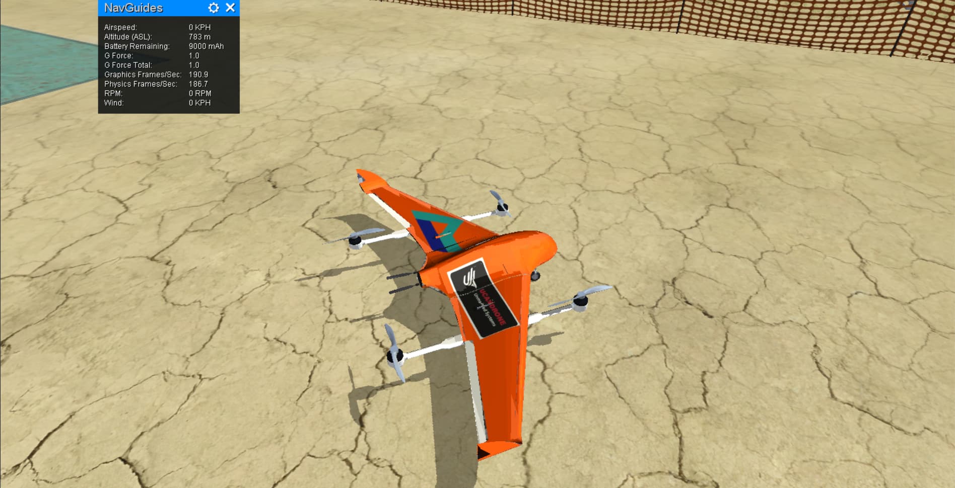
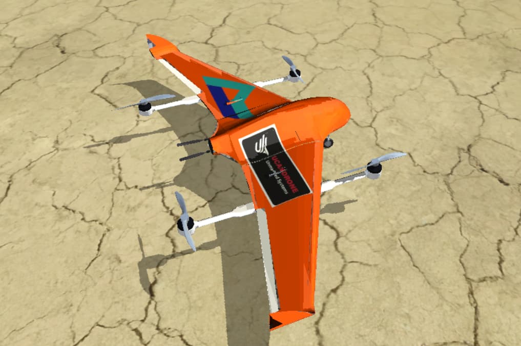
Final result
That was a long guide, and yet I know it’s not even close to being complete. Still, I hope it has been useful; it’s the guide I hoped I had about a month ago.
Many thanks to the people in Discord who helped me out and UCanDrone for sharing the CAD model that served as the example.
Fly safe!