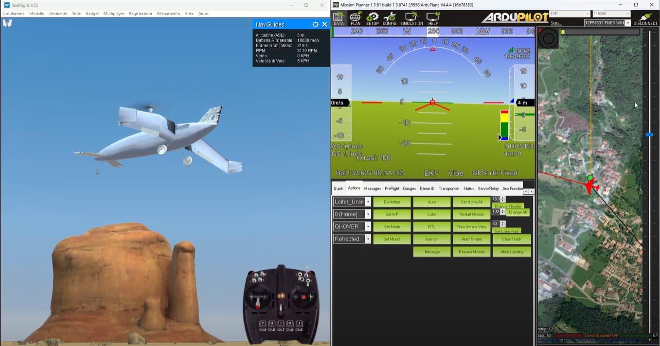
A little while ago I made a QuadPlane model for RealFlight; it turned into quite a nice blog article. But the aircraft I modelled it after had a serious flaw: The center of mass (CoM) position required to fly in fixed-wing, would not coincide with the center of the multicopter motor frame: it was quite a bit more forward.
This had the undesireable effect that every time it throttled up, the rear motors had more pitch authority and pushed the nose down. The effect was quite pronounced and the plane was not fun to fly manually. It didn’t even fly automatically well either, with the integrators taking long to wind up and having to work quite hard.
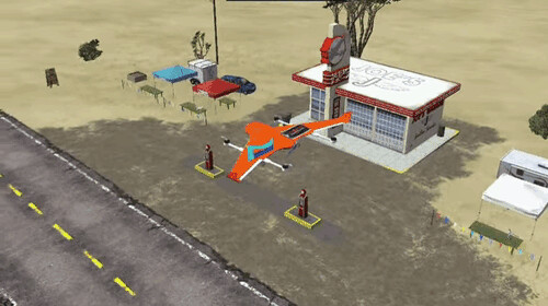
In the end, I cheated and placed the actual thrusters in a different position to their visual geometry:
But we can do better! Lua scripting supports static and dynamic motor mixing and we can take advantage of it.
Getting real
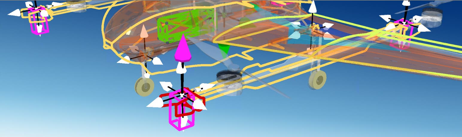
First of all, let’s restore the thruster model to its intended location. Once this is done, the imbalance is immediately visible. The forward motors are closer to the CoM and carry relatively more of the aircraft’s weight. Hence they work harder.
Yeah, that doesn’t look too good. It’s kicking like a mule.
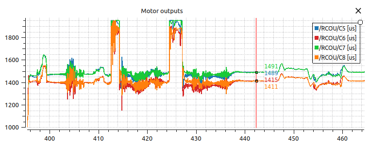
The front motors hover at around 50%, while the rear ones around 40%. The pitch controller integrator is winding up to produce pitch control and counter the imbalance.
Mixing it up
A simplified concept of the output mixer, is that of a table tasked with receiving the control signals and generating individual motor commands.
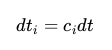
Typically, for a pure throttle signal, all commands are set equal to it (), but for the sake of this work we will accept arbitrary mixer matrix gains.
What we want is a mechanism to slide these gains to put more weight on the front thrusters and less to the rear.
We define a ratio between the gains as this slider
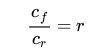
and we also need
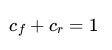
otherwise the overall thrust produced would have an altered magnitude; we only want to affect the distribution.
Combining the above two equations, we get
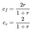
These gains are going to be inserted in the dynamic mixer, available as a Lua binding.
local r1 = 2/(1+ratio)
local r2 = 2*ratio/(1+ratio)

Motors_dynamic:add_motor(0, 1)
Motors_dynamic:add_motor(1, 3)
Motors_dynamic:add_motor(2, 4)
Motors_dynamic:add_motor(3, 2)

factors = motor_factor_table()

-- Roll stays as-is.
factors:roll(0, -0.5)
factors:roll(1,  0.5)
factors:roll(2,  0.5)
factors:roll(3, -0.5)

-- Pitch stays as-is.
factors:pitch(0, 0.5)
factors:pitch(1, -0.5)
factors:pitch(2, 0.5)
factors:pitch(3, -0.5)

-- Yaw stays as-is.
factors:yaw(0,  0.5)
factors:yaw(1,  0.5)
factors:yaw(2, -0.5)
factors:yaw(3, -0.5)

-- Throttle is modulated.
factors:throttle(0,  r2)
factors:throttle(1,  r1)
factors:throttle(2,  r2)
factors:throttle(3,  r1)
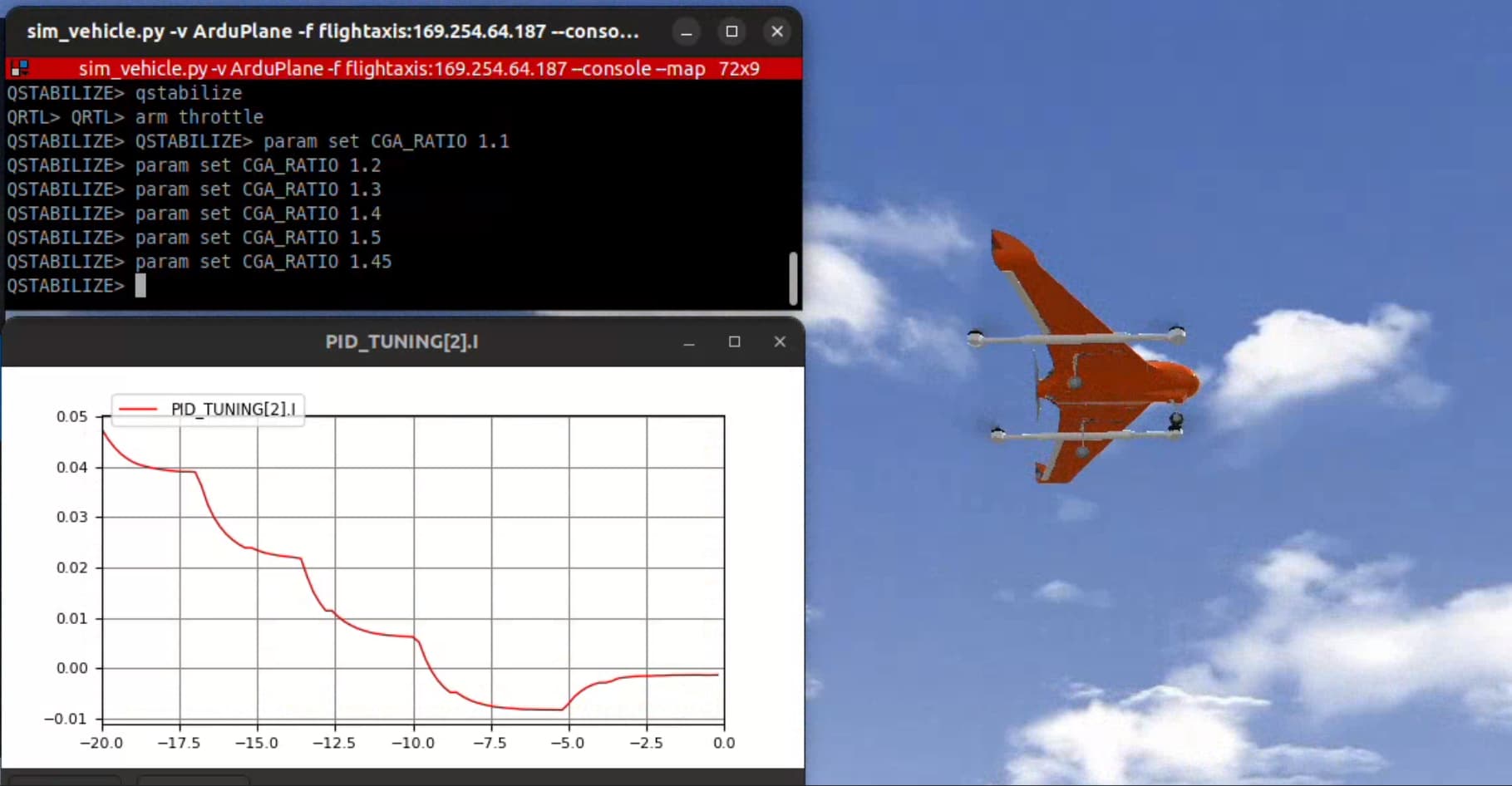
Thanks to its dynamic nature, this mixer matrix can be updated literaly on the fly by tuning the CGA_RATIO parameter!
You can find the whole script in this PR.
A balancing act
Right, let’s get flying again!
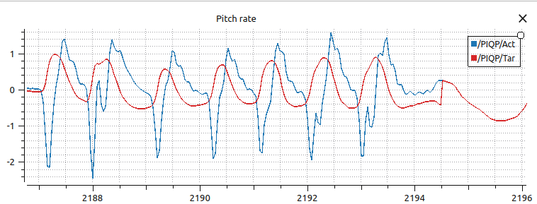
We can monitor the PID_TUNING[2].I value to see when we have hit the sweet spot.
1… 1.1… 1.2… 1.3… 1.4… stick the tongue at the right angle… 1.5… too much… 1.45 should do it!
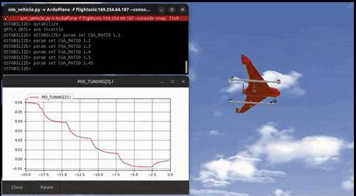
And that’s it! The golden value is about 1.45 for this vehicle.
The overall performance is much better. The pitch axis doesn’t wobble as much on throttle punches either, not totally neutral unfortunately. Perhaps this is related to the aerodynamics of the swept wing.
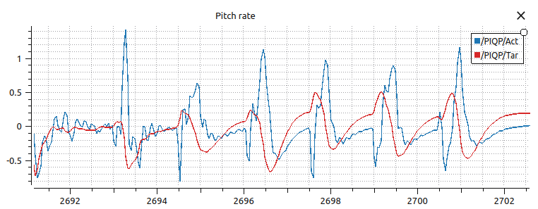
In any case, it’s definitely a major improvement compared to the benchmark!
This kind of scripting is a classic case of fixing a hardware problem in software: It would be better if the mechanical constraints were satisfied by design, but this is the second best solution. And most importantly, Lua scripts don’t increase your overall MTOM!