I’v downloaded “latest” for Pixracer and installed.
Same issue with not arming, but this time I unmasket the culprit.
It was I wrong RCMAP for Yaw. And therefore the Throttle Stick Arming could not work.
I had never to do with this Mapping, it was always OK.
And with the “latest” also the Mot Outputs work. (May be also with the Binaries from Post99)
Now the show will go on soon. @kd0aij and @losawing Thank you for your patience.
I was thinking about your Print Project. As you wrote, the fuselage could be printed vertical with rips.
And then the section glued, to avoid support material, would be difficult inside. But when you print the section bevor, you can pause the fuselag printing a the right position and then glue the section. Then the printing can continue And so on until all section are assembled.
I did this to build metal-nuts into the printing. For Cura it gave a add on to define the layer to pause. To finde the correct layer, in Cura its possible to move the layers step by step with the cursor key in order to see at witch layer nr. it print the wanted layer.
That’s a good idea; I haven’t tried that on any of my designs yet.
But the 3Dlabprint guys seem to manage internal structure (without support) by running the internal structure at an angle to the skin:
Their designs are pretty sophisticated though, and probably beyond my capability with OpenSCAD.
@lorbass None of the beta releases have support for q_frame_type=16.
Since that PR was merged into master in mid-December, it will probably be a while before it makes it into a release, so you should use the “latest” version for your quad-plus copter tailsitters.
In Cura its a param to set from which angle on a support is produced. In the video it’s good to see how they made the rib as spiral. Yes, probably needs a lot of designe work. Such internal structure I made a bit larger than the housing. Then move its vertices direction inside until they are no longer to see in the perspective view. Not to far in order not to loose the contact to the skin.
A new topic as challenge if seen this Mustang. Will make some exercices.
So you think about something like this? (You need to rename from .stl to .obj)
I made the spirals 1mm thick, but seems to small for nozzle 0.4. But wiht nozzle 0.25 they are just one line to see. (1mm horizontal is less with the angle)
Here are some photos of thinwall prints using the Cura slicer.
I had better luck printing a 3Dlabpring wing section with PLA; no stringing problems like I had with PETG.
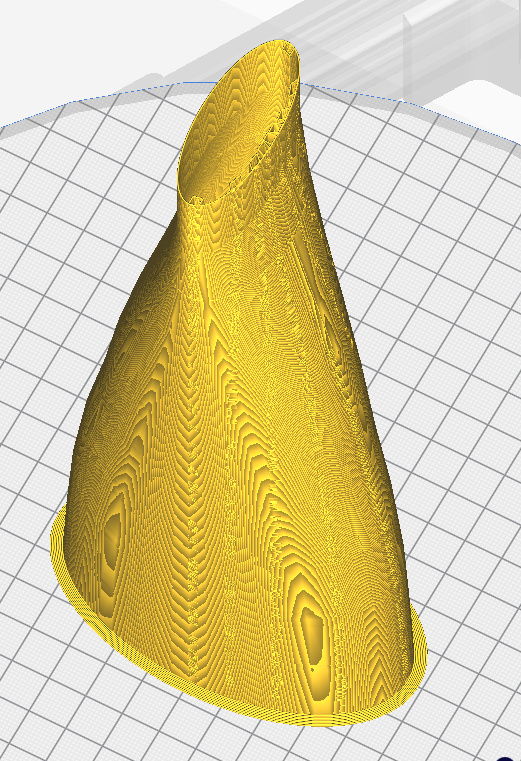
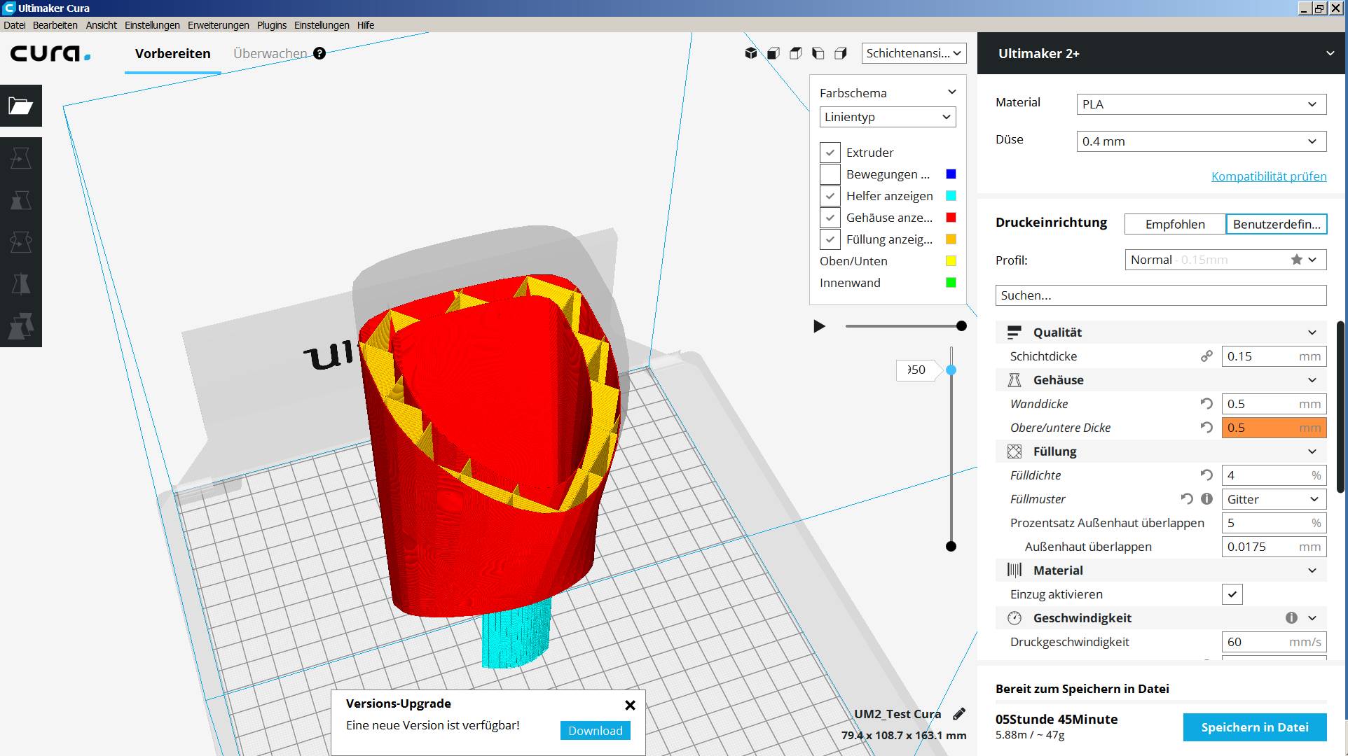
This is a part of the fuselage. (My printer is not hihg enoughe) with a wall thickness of 10 mm.
But have a look at the Filling %, Wall thickness(j0.5), Params.
0.5 because to limit one line but safe above the nozzle (0.4)
Must be verry strong. Test Cura.stl (155.8 KB) needs to rename from .STL to .OBJ
First Hover Test in the Rack. As always with some issues. https://youtu.be/zoigpQY38-Q
The Q_A_RAT Params from Mark with the SITL Tuning seemed to be close to perfect.
This would certainly be much easier than explicitly specifying thin-walled structure with no infill, since the slicer takes care of generating the walls when infill is used.
But I would guess that the strength to weight ratio would not be as good as custom designed ribs and bulkheads.
This was about 1/3 of the fuselage. Would result in about 150 gr for the whole thing
and have to be undercut first
A new issue detected. Since the Pixracer is loaded with “latest” its no more possible to connect with
two Windows 7 PC. (old Notbook to use in the field) It want to install a Driver with Name “Pixracer” wich does nowhere exists and bevore it was fmu4. With OS Win10 it works with a older Pixracer with Arducopter V4.0.0 it connects. In the net I didn’t finde a Driver “Pixracer” to download. Because it almost flies, I do not want to reboot other FW to test. Do you know such issues or where to get this driver.
I’ve never had that problem on my Win10 laptop.
In the past few years I have only used Ubuntu and Win10, so I don’t know what driver issues might exist with earlier versions of Windows.
Yes, with Win10 everything works perfect.
Thanks for the link. I did not explain it correctly, it’s not this issue and has nothing to do with MP or QGC.
Normally when the USB from PC to the Pixracer is a first time established, it installes the USB Driver.
After the Pixracer was loaded with “latest” with the Win10 PC I tried to connect it to the “Field” Notbook I used always. It started to install the USB Driver, and I was surprised because it was already. I found, to name this port “Pixracer” is a good idea. But this driver was nowhere found and so it can’t connect anymore to two different Win7 PC. Then I took the Notebook of my Wife, with Win10, and it installed the Driver normally.
I must have to do with the loaded “latest” and with Win7 only.
Do you know, where to report this issue? Because will later built in to master.
First Start in free nature with 5 kph Wind. Difficult to get it back because it starts to oscillate in Roll when Pitch is applied. But all axis are critical. Also Yaw is not stable and suddenly Yaw happened when I tried to get it back via Roll. The params from SITL behave different. Are all params to high or does one influence others ?
Expert would say it was more a soft crash than a hard landing finally with a salto mortale backwards. But no damage.