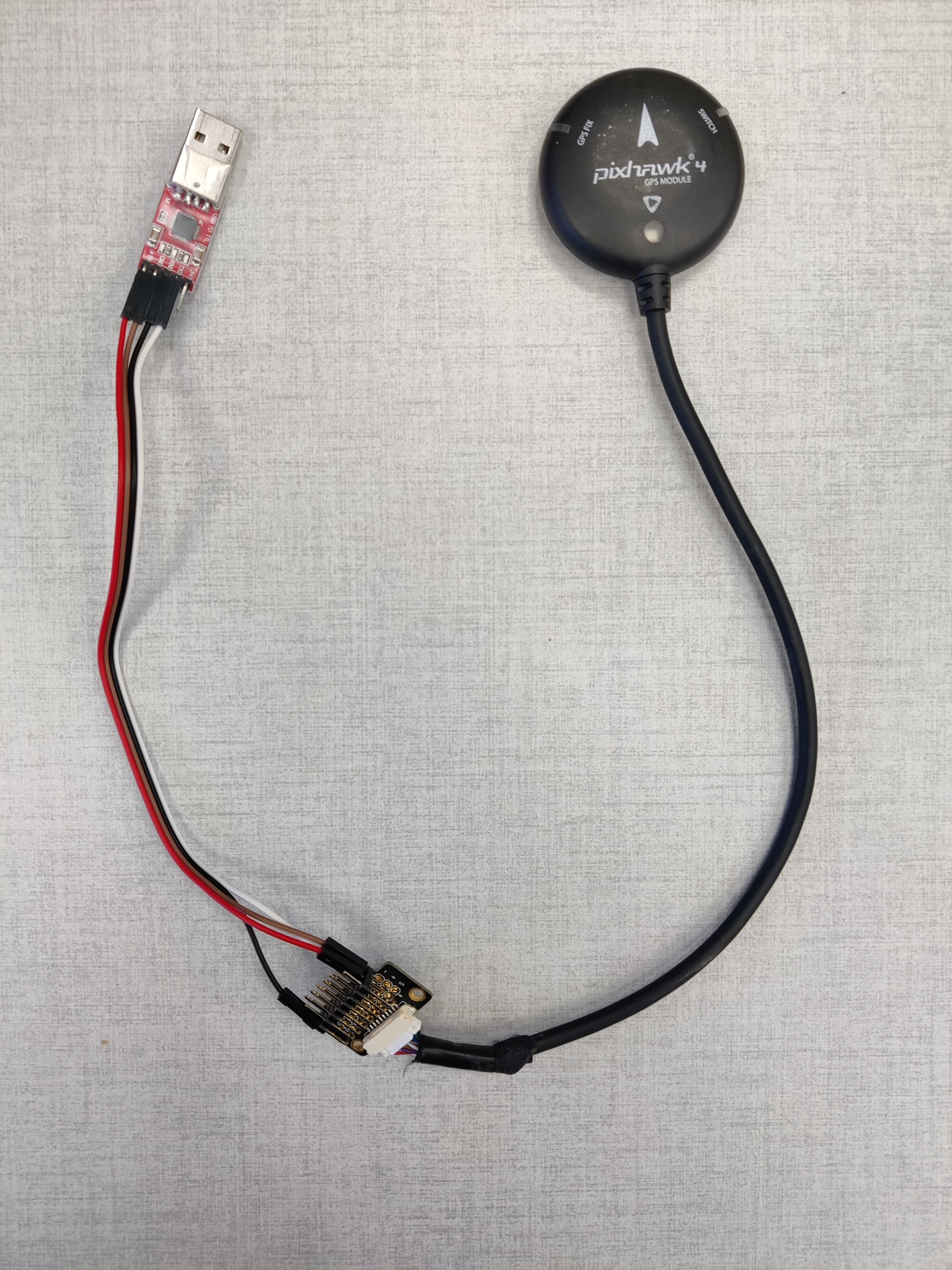
Hello, I have a Holybro NEO-M8N Pixhawk 4 GPS module that I want to connect to my laptop and read the output (NMEA sentences hopefully). I have a CP2102 USB to TTL bridge, I connected the 4 pins (5V, GND and TX/RX) correctly according to the pinout of the GPS and plugged the USB to my PC.
It looks like this:
I then use PySerial to connect to COM8 with 38400 baudrate, yet I see no output. I don’t even know if the GPS is on since the LED is not blinking (I guess it shouldn’t since the LED pin is not connected?), but I know I’m in a good spot to get a fix because I used it through a Pixhawk without any problem.
Do I need to connect all of the 10 pins to get it to work? Is it only possible with the separate NEO-M8N GPS? or am I missing something else?
The four pins you referenced are all that’s required. Even without the LED pin connected, you should still get some LED activity on the safety switch, though it is less useful than the full measure of notifications that happen when everything is connected to the autopilot.
Where did you get the breakout board ?, You’ll may need the Ublox u-Center software as well if the GPS is set to Ublox output rather than NMEA. But triple check you wiring.
Agreed that u-Center is likely the preferable monitoring/configuration software, but there should still be serial data visible on any properly configured terminal.
Hey, thank you for the quick replies,
I have indeed already used U-center to configure the GPS to output NMEA, but now I need to get the output directly in my python program, that is why I switched to PySerial. Is there a way to get the output directly from u-center? if yes that would be great.
And yes I checked the wiring countless times so I’m pretty sure it is correct, could be that the pin adapter in the middle (I don’t know what it’s called) is faulty. I couldn’t find a 10-pin to USB cable with a connection like the GPS module has, so that is the only solution I have at the moment. I will try to replace it, and if anyone has other ideas I’d really appreciate it.
Sorry, I should’ve been more clear. When I connected it to u-center it was through the Pixhawk, so it wasn’t directly connected to the PC yet. After I switched to what I have now u-center didn’t work either. I guess bad wiring could still be the issue, so I’ll keep testing…
Regardless, thank you very much for all the help!
By “check” you mean test if it gives out power? (Sorry I just don’t actually know much about electricity and this kind of stuff)
If so, then I’ll only be able to test it on Sunday unfortunately, but I’ll update what I find here. I won’t be surprised if this is the problem.
Oh yes sorry, that is what I meant I’m just bad with the technical stuff. My coworker who is an electrical engineer tested it with a multimeter and basically told me it is working, but I will ask him to check again when we are back in the office on Sunday and update the results here. Thank you guys for all the advice.
Hello guys. so we did the tests that you suggested, we tested the voltage from the 5v pin with a multimeter, it measured at 5.05 on the USB end and the GPS end, so I’m pretty sure that part is fine
(even though there wasn’t any LED blinking).
I also asked my coworker to check the TX/RX pins, using something called an oscilloscope, and a strange thing that he noticed is that the RX pin of the USB was always giving out waves (forgive me if
I use incorrect terms), even though I wasn’t writing anything to the GPS obviously. The TX wasn’t giving out anything. We triple-checked that the pins were connected correctly, so it’s not that.
If anyone has any other ideas please let me know, otherwise I guess we will try to buy the separate NEO-M8N and try with that. Thank you for all the help
You could check on the adapter (breakout board) wires on the GPS side to see if it has 5 volts on it’s 5v pin (between the 5V pin and GND) - the adapter could be suspect - could you show a picture of the pcb track side to see how it’s wired.
It could be that the USB port can’t supply enough power to power the GPS module but I doubt it though. The waves you saw on the oscilloscope could be ‘noise’ or data depending on the level of the signals and the ground of the scope.
You really need to get a cheap multimeter they are incredible handy for loads of things, I would get a multimeter before you go out a buy another GPS module.
I am 100% sure the wires are correctly connected, and we did try to swap them but it didn’t help. And yes we checked the wires from the USB and the GPS and both were 5 volts
The GPS manual said the baudrate is 38400, and I tried 115200 and 230400 aswell, but you’re right that it’s a good idea to check every option. I will only be able to test that and the RealTerm software on Tuesday, so I will keep this updated. Thank you guys so much for the help.