Chasing better accuracy

WARNING: Many words ahead…

I work with large rovers where following a precise predefined course is a critical success factor. Over the last year or so, we have refined our systems and tuning to the point where we can rely on averaging better than +/- 5 cm cross track error on straight sections of the planned path. This represents approximately 2% of the vehicle width. This degree of accuracy has come about due to an increasing understanding of how Ardurover works at all levels. One thing that is apparent when looking at position information at this scale, is the degree of apparent noise.

We use Ublox F9P GNSS modules in a moving base line setup on our vehicles along with our own local base station (also F9P). This arrangement gives us an heading that is not affected by magnetic interference and accurate to approximately 0.1 degrees, along with a position that is repeatable to within better than 1cm.

The Ardupilot code uses the ‘Location’ object to represent locations on the surface of our planet. This object stores latitude and longitude in decimal degrees * 1.0e07 as a signed 32bit integer. When determining the relative positions of two locations in meters, the code applies a constant multiplier based on the circumference of the Earth. In the case of longitude, a further scale factor to account for latitude is applied. This gives us a fixed resolution of ~0.011m in the N/S direction and the same in the E/W direction at the equator, but getting better the further N/S you go. This constant can be found here in the code: https://github.com/ArduPilot/ardupilot/blob/master/libraries/AP_Common/Location.h#L124 LOCATION_SCALING_FACTOR = 0.011131884502145034

Even though the Location object is limited to ~1.1cm resolution, the EKF internally uses a position represented by the NE offset in m from the origin location. This offset is represented by a float variable which should give approx 7 decimal digits of precision. This equates to a resolution of 0.0001m over a 1000km range - (better over a lesser range/ worse over a greater range).

Given the EKF internal resolution is better than the external location position by at least a few orders of magnitude, it does still rely heavily on regular location updates from the less precise GNSS module/s attached. Most of these modules in use today only supply the same 7 digits of precision that the Location object uses, with some only providing six. However, there are modules available that offer greater precision output. The Ublox F9P for instance, has the UBX HPPOSLLH message that offers the standard 7 digit lat/lon attributes but also has additional latHp and lonHp attributes that each represent additional precision. When these attributes are scaled appropriately and added to the lat/lon values, we get a measurement that is precise to 9 decimal places. This is roughly equivalent to 0.1mm. Of course this is not to say that we now have a position that is this accurate, but at least we can now be assured that the accuracy is not being eroded by the precision of the reported value - which was not the case with only 7 digits on this particular module.

To test the degree to which this lack of precision potentially affects navigation, I set about adding support for the additional precision available from the F9P. This included:

  • Updating the Location class to support storing the additional latHp/lonHP attributes
  • Updating all the Location methods to utilise the additional HP information in their calculations
  • Adding support for processing the UBX HPPOSLLH message
  • Adding the latHp/lonHP attributes to the GPS dataflash log entry
  • Adding the ability to encode latHP/lonHP into the MAV_CMD_NAV_WAYPOINT param1
  • Adding support for outputting the UBX HPPOSLLH message in SITL

The code for this is available here: https://github.com/jimovonz/ardupilot/tree/hp_location. This branch is based on Ardupilot master July 8, 2020. This is experimental code and has not been flight tested.

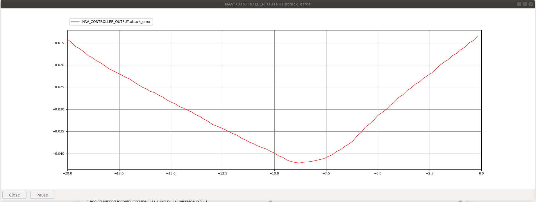
Some testing in SITL using rover default params shows some improvement with respect to the high frequency variability in cross track error as well as overall accuracy:

hp_location:

master:

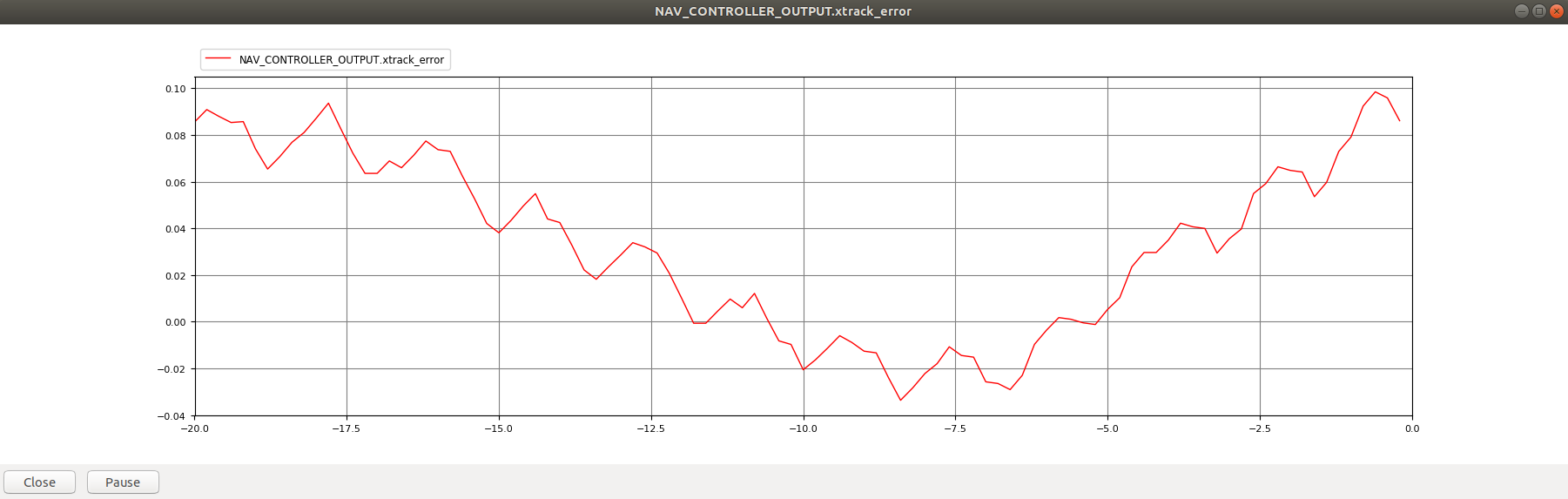
These graphs show the cross track error for roughly the same section of a straight path in the SITL simulator using the standard and modified code.

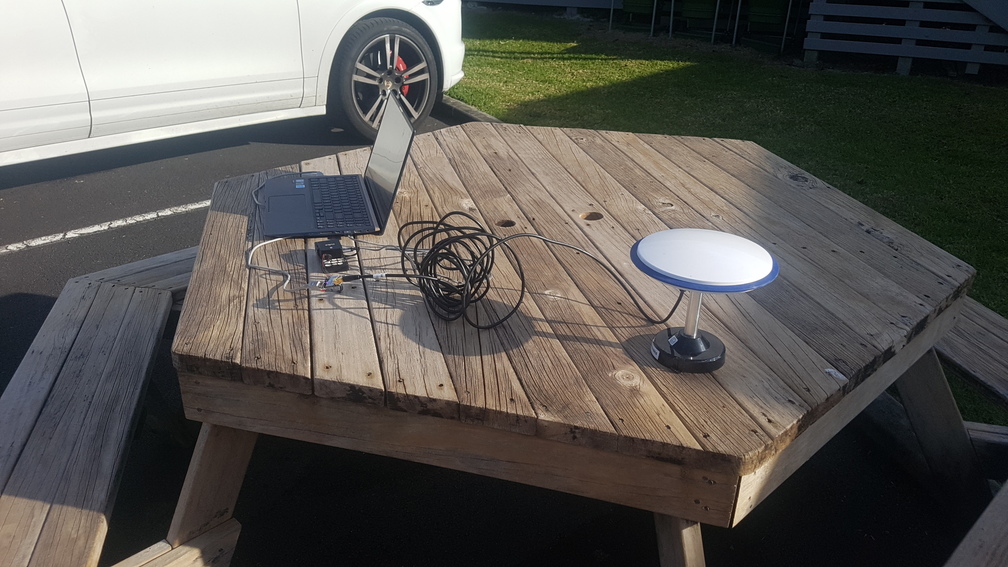
I have also done some limited testing using a stand alone Pixhawk Cube Black and an F9P (not attached to any vehicle platform). Looking at the reported EKF position, I can see a what subjectively appears to be an order of magnitude reduction in the variability. This would be in keeping with the simulator results.

Unfortunately I am not going to get a chance this week to test on an actual vehicle as all the available machines are currently in the process of testing various other critical systems.

I will add additional testing data as I can.
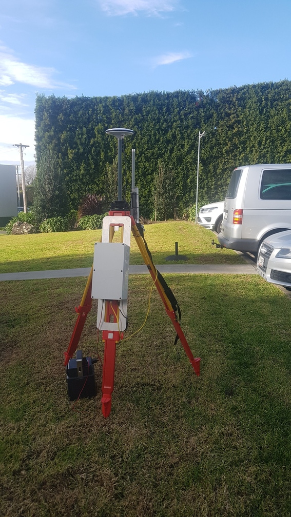
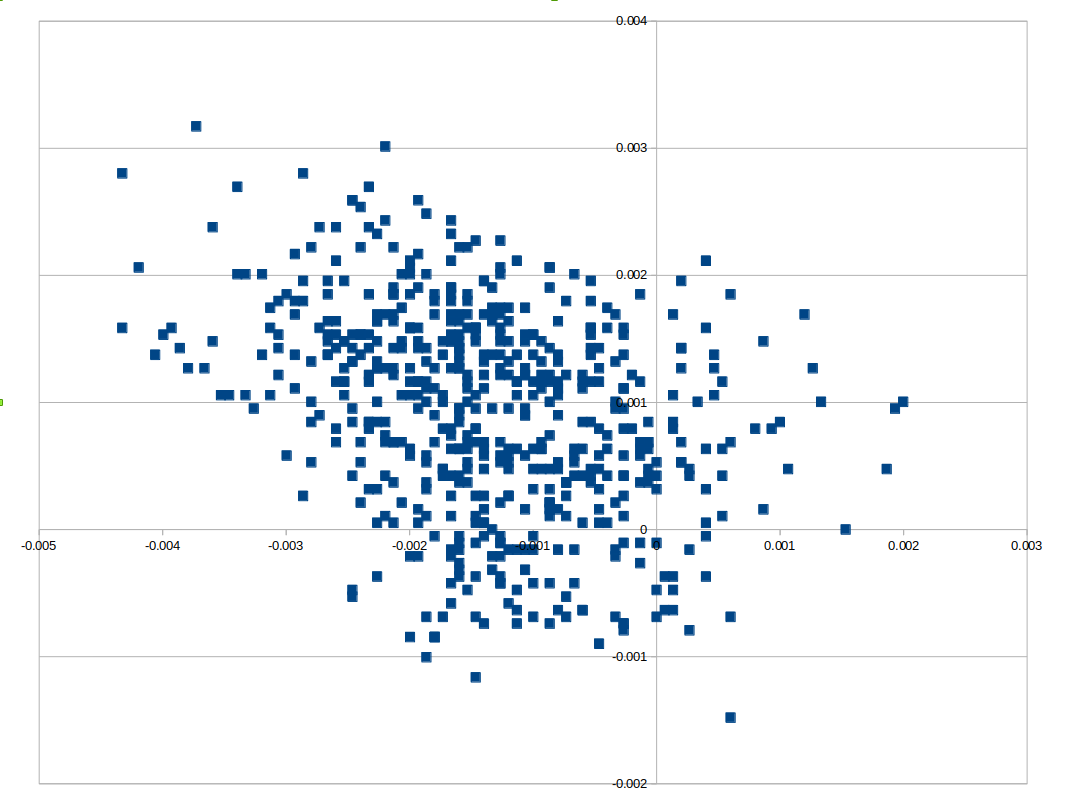
Added July 14:
I have repeated the static test and recorded data. Below are the results of setting up the Pixhawk and F9P with a local base station and recording a dataflash log for approx 5 minutes. The plots show the EKF PN vs PE in m (position North and position East) for the standard code and for my high precision code:

hp_location:

master:

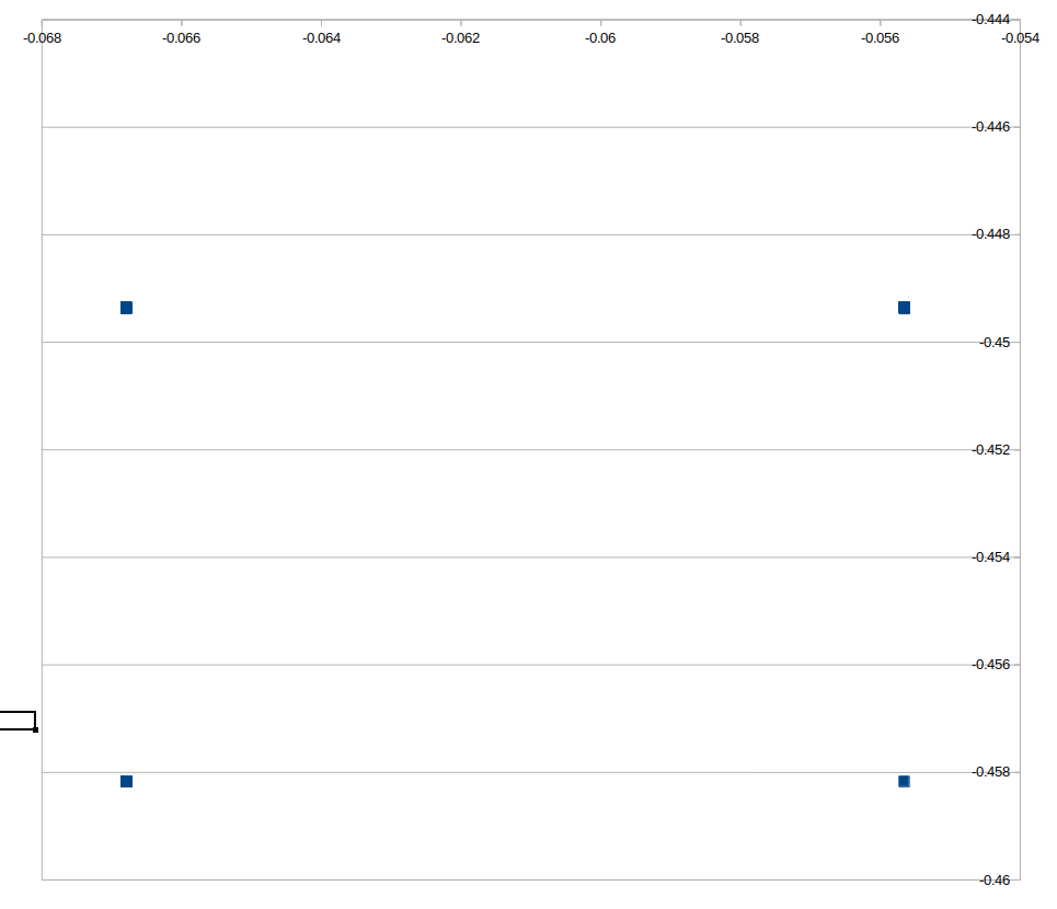
Note that the stock code from master resolves all location readings taken during the interval into 4 specific coordinates. The distance between these points represent the resolution limit of this code.


8 Likes

Excellent ! Feel free to open a PR to support those GPS message

2 Likes

I’m quite skeptical about the real improvements this will bring. The phase center of most GPS antennas is really not well defined down to that level, and often is different for the different frequencies (so on the 3 bands the F9P uses it may have a different phase center, and thus a different position).
To really do this properly would require a lot of changes in the code and in MAVLink protocol (as we sent 1e7 int32 now), plus in mission storage formats, logging etc.
I’d want a lot more evidence of real benefit before we went down this path.
Cheers, Tridge

1 Like

Hi @tridge,

I appreciate your scepticism and I am not entirely sure what the the actual gains will end up being yet. All I know is that in our case we are approaching the limits of the current location precision and I am looking to push this limit in an attempt to get the best possible result. Even if there are reasonable gains to be had, I doubt that many will be in a position to utilise them. As you say, often GNSS antennas are a compromise on size and cost and there are many factors regarding vehicle setup and tuning that would render such accuracy improvements moot. In our case, the antennas we use are ‘survey’ grade and have an advertised phase center accuracy of 2mm across all the frequencies it is designed for (which include all those usable by the F9P).
I think that cm level accuracy is achievable with recent low cost GNSS modules and if we want to make the best use of this, our underlying calculation accuracy needs to be at least an order of magnitude better.
With regard to code changes, I also agree that a ‘proper’ solution would involve many changes, however I have addressed the most obvious requirements in the code linked above. I have handled the basic MAVLink, mission storage and logging support for this extended precision. Using this code it is possible to design a mission with waypoints specified to 9 digit lat/lon, upload it to the FC and execute it with the GPS message logged to the dataflash at the same precision. Obviously there is more to do for a complete solution but I think that I have illustrated one way this can be integrated into the existing code without too much disruption.

3 Likes

Added some static test data

Have you had a chance to see if these changes work on a real mission on vehicle?

@Reuben_Finch I have done some testing and I have seen improvements but unfortunately due to having restricted access for this type of testing, I ended up testing a number of changes all at once. These included changing from moving baseline heading to calculating heading based off the two independent GNSS rtk locations (both GNSS set up as type 2 - stand alone Ublox modules) and increasing the GNSS navigation rate to 25Hz (achieved with some code changes to allow over 20Hz and restricting the F9P to only 3 constellations - which still gives ~25 sats). In addition to this, I also made some tweaks to the L1 controller to more aggressively follow the path when the cross track error is small.

Prior to these changes we would achieve an average xtrack error of ~5cm on straight sections of a mission and a max error of ~15cm (typically the max error occurs just after completing a turn). After these changes we are seeing ~2cm average xtrack with a maximum of ~5cm.

I still intend to do some testing in an attempt to isolate the effect of the increased location accuracy but I am not sure when I will next get an opportunity as all the available machines are quite busy.

At this point, I am not inclined to pursue any further improvements in straight line accuracy but will instead work on the turns where I would like to plan and achieve a specific arc.

2 Likes

I’m testing your changes to the L1 update_waypoint() function.
There is a part I’m confused by.

Nu1 += _L1_xtrack_i;

if((_crosstrack_error > 0 && last_xtrack < 0) || (_crosstrack_error < 0 && last_xtrack > 0)){
Nu1 += (_L1_xtrack_i/2.0f);
} else {
Nu1 += _L1_xtrack_i;
}

From this it seems that if we get to the ‘else’ then we will have added _L1_xtrack_i to Nu1 twice.
Should the first line be removed in your changes?

I found some improvement by reducing the frequency that the ‘update_current_mode’ in scheduler. But I will test changing that back to 400Hz.

1 Like

@Reuben_Finch I wouldn’t take much from any changes to the L1 controller in this branch. I specifically removed any changes I made when committed this so as to make a fair comparison with the original code. It looks like I missed this chunk. However, I do not use any I gain on the L1 controller so this would not have affected the outcome. This piece of code does look unusual in its application of the i gain. I did play with reducing/zeroing I when crossing the path but never came up with anything useful.

Hi @jimovonz

I’ve been reading your code carefully and I’m eager to test the results of it.

I have only one doubt, in the offset function of the Location.cpp library you can see that you added two fixed values (-0.05 to the lat and 0.08 to the long) ​​to the gps readings:

double hplat = (double) lat - (double) 0.05f;
double hplng = (double) lng + (double) 0.08f;

I would appreciate if you can help me with the following questions:

  1. What do these values ​​represent in relation to the antenna reading?
  2. Why is it necessary to make these corrections to the antenna reading?
  3. How is the procedure to obtain these values?
  4. Can these values vary in different circumstances or do they maintain the same trend?

Thank you @jimovonz, have a good day!

2 Likes

HI @Alon_Druck, Good catch - this code sets a fixed offset to the HP portion of the result. I used this when debugging and this should not be in the code. I have fixed this now.

1 Like

I’ve been using your version of the code for a few months now and didn’t notice this offset. I’ll remove it and see what changes, if any,
result.

2 Likes

Do you think this PR will be merged at any point? I’m quite interested in seeing what it does to PPK data.

@Saijin_Naib I do not think there is much appetite for adding this specific code - it was only experimental and somewhat of a ‘hack’ to get the extra resolution with minimal changes. To be properly useful it would require a lot more work. We have moved away from using Ardupilot and so unfortunately I am not inclined to spend much more time on this.
I do not think these changes would have any effect on your PPK results. PPK relies on the raw data from the GNSS module which is not affected by any of my changes.

1 Like

Ah, unfortunate, but thank you for what you’ve already accomplished with this line of work. It looks like it at least was headed in a very good direction.

Good point! I’m not certain I would PPK all of my data, so having the baseline non-PPK readings be boosted by this code is still appealing.

2 Likes