I am upgrading from Pixhawk1 to Avioni Hex Board with Orange Cube. On my Pixhawk1, I had a telemetry cable which went to serial 4/5 (external port) and allowed me to get telemetry data on my taranis radio. I’ve found a new cable for Pixhawk 2.1/Pixhawk 3/Pixhawk 4/Pixracer/Minipix which I think should be the one for the Hex boards: http://www.craftandtheoryllc.com/store/ct-telemetry-cable-for-frsky-radios/
All the Pixhawk 2.x telemety cables I see are basically the same.
The problem is, and reason I have not ordered one is because my Hex board does not have an external serial 4/5 port to connect to. I am very hesitant to take apart my brand new board and even more hesitant to go splicing in a cable internally, especially since I read that the Serial 4/5 port on the newest Hex board is already in use by the ADS-B. I am pretty unconvinced it would even work with two devices hooked up to the same port. If it were a daisy chain port, maybe, but a serial port I thought was for one device on one port is my understanding. I did see in the Ardupilot documentation that “due to space constraints two ports are on one connector.” on the Pixhawk1, so… maybe? Is there another way to connect a cable for telemetry data? Taking apart the Hex board just does not seem right.
The 2nd cabling question I have is: My power cable that came with the new board is too short. I have another one that is slightly longer (came with my power module sensor) but it is also just barely too short. I can’t seem to find any longer cables online. I have been searching for JST-GH connector cables, but not finding any long ones. Should I just splice it twice with a little piece of cable? Will this create resistance or throw off my power module’s sensor? I am hesitant to move my power module’s sensor because I don’t have a good place to mount it close to the board, but at the same time, I am hesitant to put two splices into each wire.
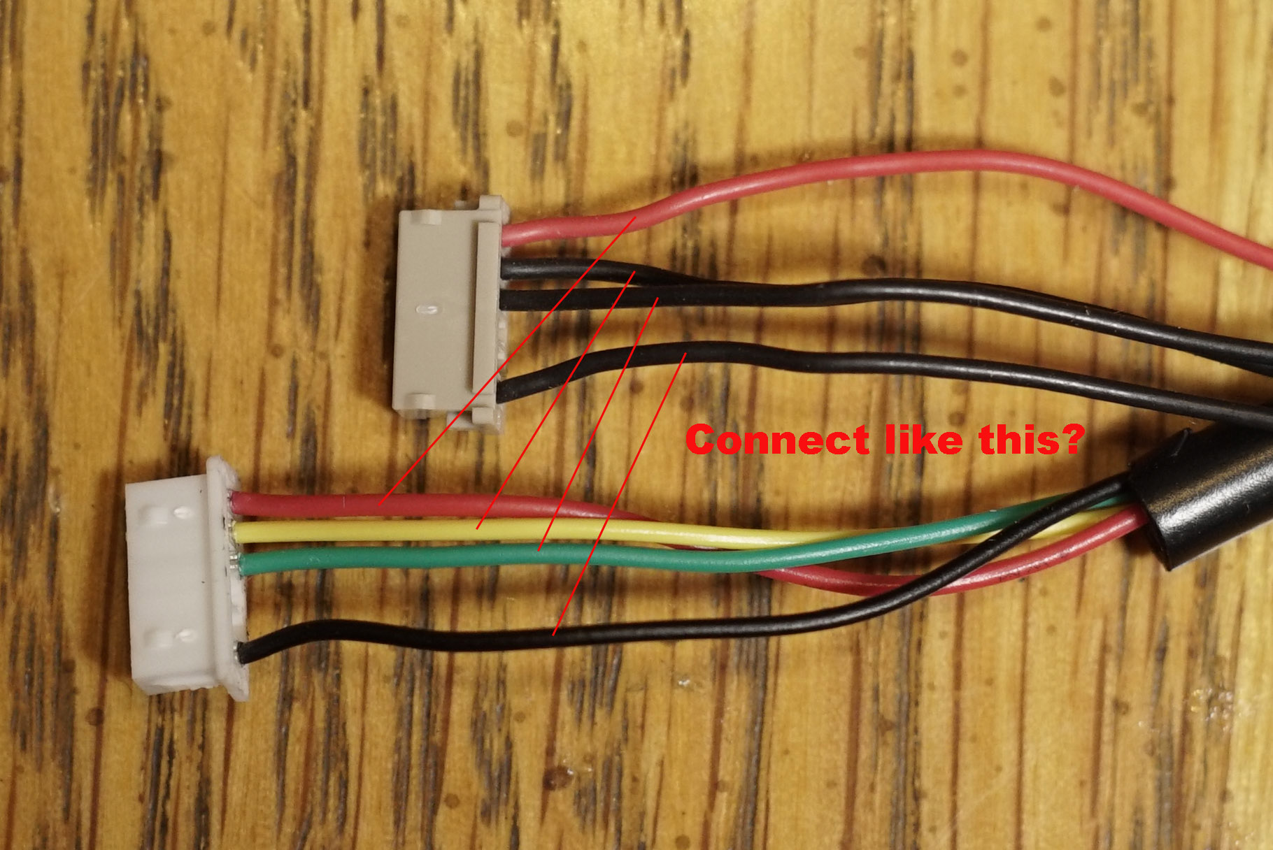
I have two GPS units; one I bought just recently, and the 3DR one which came with the Pixhawk1. For the first GPS, my cabling question is: My Pixhawk1 GPS cables are color coded and there are 4 wires coming from the gps’s, plus two more for the 12c port. On the new Hex board, the cables are not color coded, but it looks as if they are simply exactly reversed in their order of connection to the connector. Without color coding, I’m not certain about the two centermost wires. The red and black I am pretty sure would connect to red and black, but the yellow and green I don’t want to get backwards. Can just splice them all to their opposite positions from the Pixhawk1 and it will be correct? I don’t like the idea of just guessing it and hoping it’s correct. Can anyone validate? Picture below:
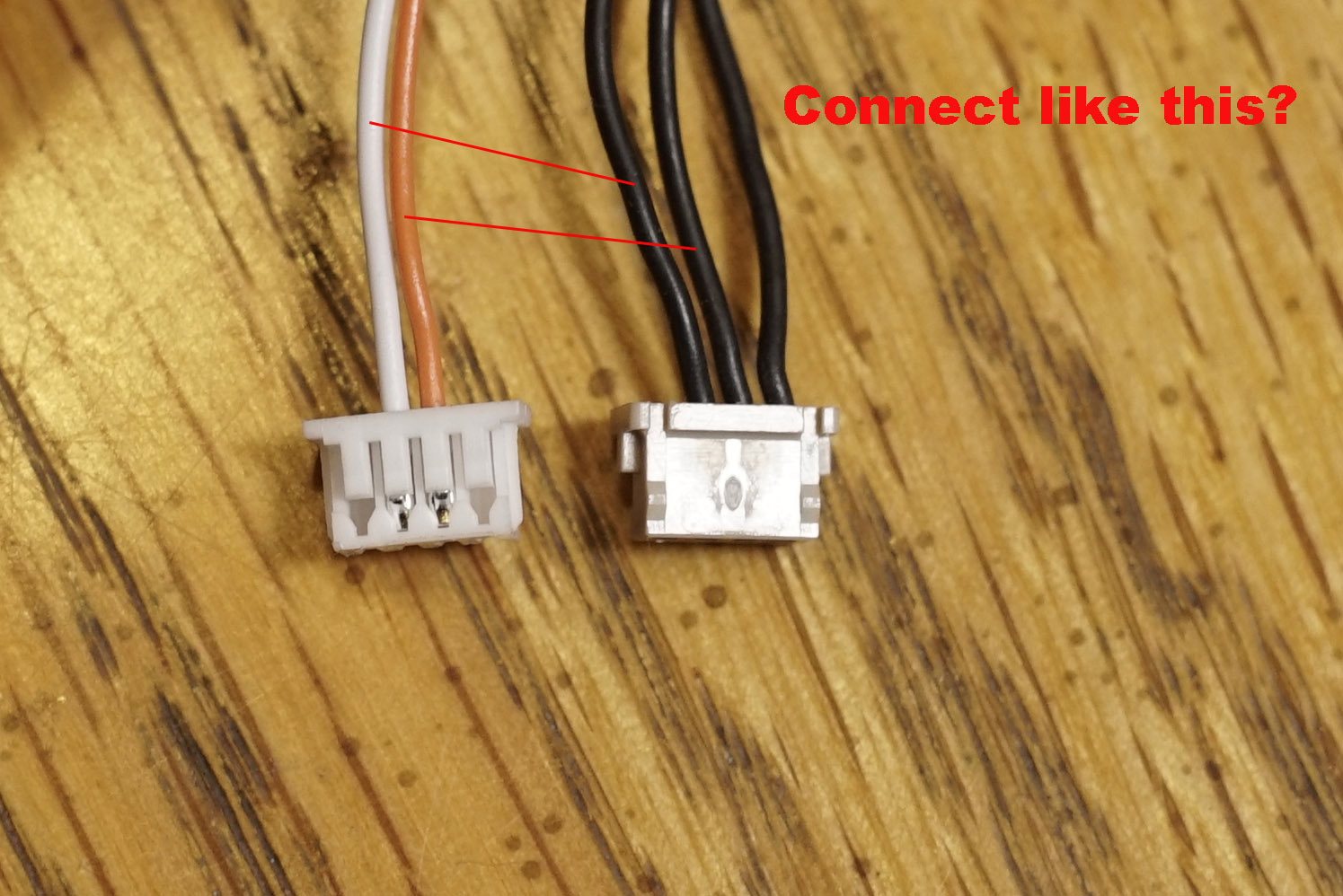
Then there’s the 12C connection for the GPS unit. My GPS unit has only two wires coming out for connecting to the 12C port on the Hex board, but the new cable has three wires in use. I think I should be connecting the middle two wires to the middle two wires on the new connector, but no idea which cable to which side. This would mean two possibilities:
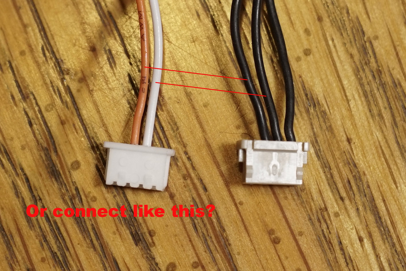
Or another way entirely?
For my second GPS, the 3dr which came with Pixhawk1, I have six wires coming from the GPS unit, but only 4 wires to connect to on the new connector:
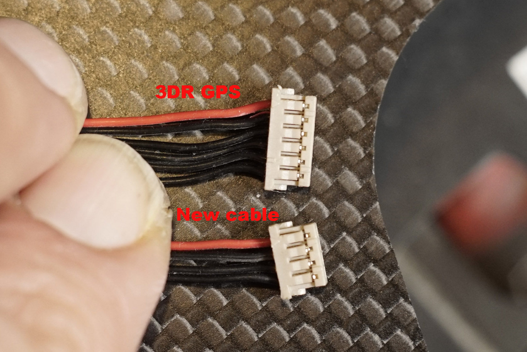
Where do the extra 2 wires go, and which two are “extra?” For the 12C connection, I have 4 wires coming from the 3DR unit, but the new connector only has 3 wires:
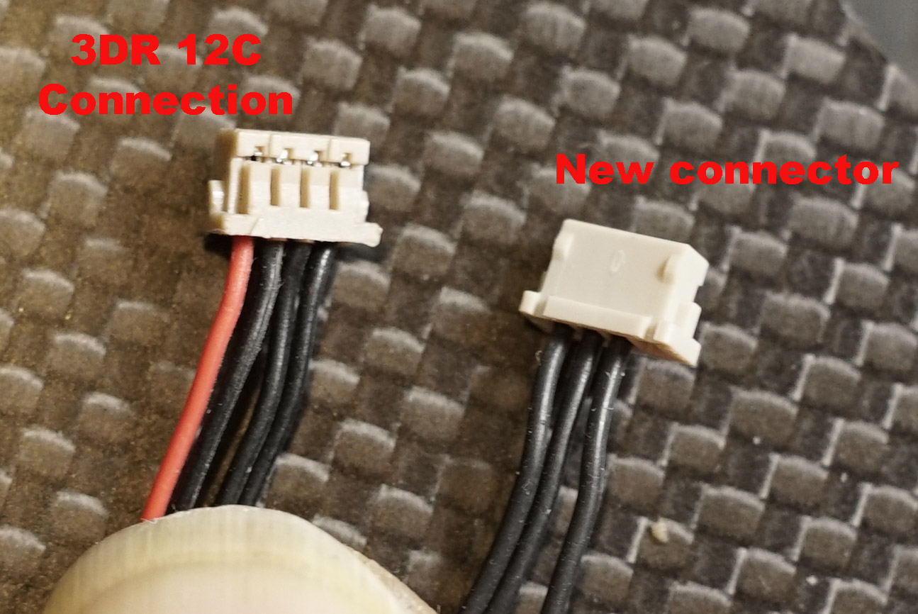
What do I do about this?
All of this has left me wondering: Is this one of those situations where if you upgrade one thing, you have to upgrade and replace everything around it? Maybe there are cables I can buy which save me the need to do all this splicing?