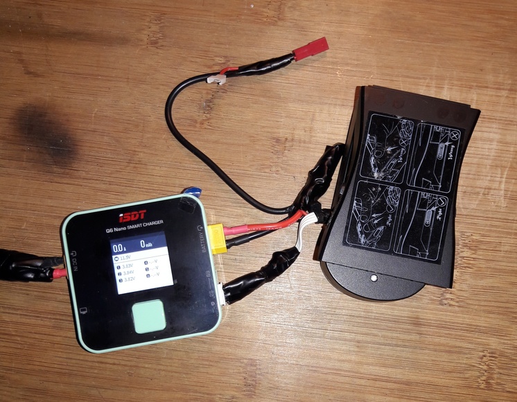
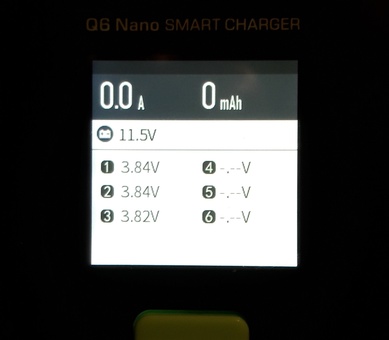
So here is my Q6 Nano wired for the EX4 batteries. Not pretty but it seems to work. While I was at it I added connectors for single cell batteries as well. As you can see the initial battery connected was out of balance but not too bad at the moment (at one point I thought I saw a .04 volt differential, but I believe that the balance connector was not plugged in properly aligned at that point). I haven’t actually tried to charge yet – my next test will be to take the battery to a storage charge level.
A few things to keep in mind. The wiring in the attached EX4 charger uses pretty thin conductors, I’m not even sure the connectors for the battery on there are hefty enough for the charging to occur as high as 1C. This will be tested. Also, a three cell balance plug can be easily misaligned and give false readings in that case, and you also need to be sure that it’s firmly plugged in since the balance plug socket isn’t very tight. Finally, since there are identical battery connectors on both sides and the unit is a cube, it’s easy to accidentally plug the power supply into the battery charge side, though this doesn’t appear to cause any damage (this was determined, uh, empirically).
Overall this seems to be a practical and economical setup.
So the stock charger only has what would be considered balance leads, so in order to get the Nano to see it as an actual 3S LiPo you’ve connected the XT60 plug to the 11.1V and ground points, right?
I cut the existing wiring, splicing to those conductors rather than soldering directly to that connector board I showed in my previous post, except for the 11.1 where I soldered directly to the pad (the board is fairly fragile, I didn’t want to solder directly to it except where I really needed to). I removed the existing main circuit board entirely.
The XT60 is tied to 11.1 and ground, and the balance plug leads come off the connector board at ground, 3.7, 7.4, and 11.1.
Running some initial tests now. Note that since I haven’t want to force any sort of probes in the battery side contacts, I don’t know for certain that tapping the connector contacts on that connector circuit board in the charger gives completely accurate readings, or if any circuitry left on the connector circuit board (the LED is still there, for example) loads down the voltage in any way. For now I’m assuming tapping the connector circuit board is accurate enough.
Tried to storage charge (in this case discharge) an EX4 battery. It seems to start each time, but also seemed to stop early each time with the completion bar only partly finished. And it seemed to stop on individual cell voltages that were higher than expected (storage charge for these batteries should be 3.85). After a number of restarts one of the batteries got down into that range or a bit under, with up to .03 volts or so max difference between cells. The other battery acted the same way, but I could get it to stay under about 3.89. When I’d restart for storage I’d see it momentarily dip down toward the right range, but always the voltage went back up to around 3.89 and the unit no longer showed discharge current (though again it did not signal completion, the bar graph was incomplete, and the only way I knew it wasn’t still discharging was that the current dropped to zero and the fan noise – and it’s a powerful fan – had slowly ramped down to being completely off.
I also tested a few single cell lipos. I’m not sure the unit can discharge these at all. The total voltage (set to 1S) was correct, but discharge did not seem effective, or at least was so slow I couldn’t see it happening. I kept the balance plug disconnected since when I connected it (from the EX4 charger) I saw a couple of strange voltages on cells 2 and 3 (nothing on 1) and the total voltage was too low (like 3.81 when I knew it was actually 4.0 – turns out they were stored that way for a long time unfortunately). I will look into these one cell issues later, I have not yet tried to charge one with this unit.
Right now I’m doing my first lihv balance charge on an EX4 battery using the unit.I’m using a 1A charge rate (I also used 1A for all my 3 cell and 1 cell discharge tests) so it’s a bit less than 1C for the EX4 batteries. Right now it seems to be slowly charging with about a 0.1 differential between cells now (it was more like .03 or so before I started, maybe .04). I should be able to see cell resistance during the charge I think, let’s take a look … approx 68 53 49. Hmm. Unfortunately, there are a lot of variables when trying to get this measurement. they look extremely high, but it’s difficult to be sure exactly what they represent in this setup. When I went into cell resistance mode the fan came on after a few seconds, at least on the first try – and it went off again when I returned to the cell charging screen. The fan hasn’t been on during charging so far (it did come on later during charging). This battery hasn’t been used that much at all and those resistance values seem extremely high. I’m unsure if I trust them and wonder if the wiring issues I mentioned earlier may be a factor. Of course since the cells are in a sealed case I can’t easily check for puffing, etc. That’s very unfortunate. We’ll see how the other battery reads when I try charge it. I’m going to try take this one back down to storage voltage when it finishes charging.
Ran an EX4 battery up to full charge (4.35 per cell) and then down to storage charge (3.85 per cell). Seemed pretty accurate. Voltage variations between cells evened out pretty well eventually. The high/uneven internal resistance values are probably due to my wiring and the way I’m connected – those kinds of readings are really only useful for comparing against other batteries on the same charger and looking for sudden increases – the absolute values are not very meaningful without more specialized measuring equipment. I still don’t know if the displayed voltage values actually are the same as the true cell values (due to the connector board issues I mentioned previously) but I’ll eventually get a direct reading from a battery or via QGC. I’ll probably run a second battery through the same sequence later today. It took a bit more than an hour and a quarter to go from full charge to storage charge at a setting of a 1A discharge rate (which throttled down as it got close to the voltage target). That tiny fan is rather loud at high speeds – which is how it runs during most of discharge. Seems quite effective though, nothing got noticeably hot.
FYI, internal resistance for second battery: 42 27 40 – these values have changed slowly as charging progresses and were checked initially significantly earlier in the charging cycle than was the case with the previous battery reported above.
By the way, the instruction manual for the Nano is extremely sparse, and doesn’t even explain what the different colors mean as charging ramps down (the charger never really stops, it eventually turns blue and keeps feeding in between .2 and .4 amp to maintain the target cell voltages and balance – that is, it keeps balancing the cells and beeping at you until you unplug the battery or manually stop the charger (just removing the battery works fine to return the charger to its idle state). However, the manual for another version of the Q6 goes into much more detail, and explains what green, blue, etc. really mean. Presumably these descriptions also apply to operations of the Nano, which appears to have essentially the same firmware. Here’s that other manual: https://www.isdt.co/down/pdf/Q6_Plus_en.pdf
On an earlier point, if we assume the EX4 charger did a fair job of balancing the cells itself, the fact that they were in reasonably close balance when I first hooked up an EX4 battery to the Nano suggests that the Nano readings (at least relative readings of the cell) are fairly accurate with this setup. The total voltage would need to be confirmed another way, and I’ll probably do that shortly through one technique or another.
So basically the stock chargers are charging the batteries correctly, right?
In that case all the swelling packs should be due to faulty batteries or too much heat when used or over discharging?
I’m trying to figure out what I’m doing wrong since out of my 10 packs (12 in total but two I’ve discarded already) now I have another 3 packs that don’t give much flight time, only a couple of minute’s worth after taking even 24h+ on the stock charger to completely charge up which isn’t normal since even when the charger showed the green LED the packs weren’t balanced at all, some had up to 0.1V difference which is huge IMHO.
Your batteries may be balanced and at the right voltage but if not charged correctly the internal resistance will increase - once that gets very high they will only last a couple of minutes and are effectively no good.
The stock charger takes hours to charge whereas normally they would be charged and discharged at 1S and should take about 1 hour to charge (by definition + some balancing time) which may keep them in better condition and so last longer and give more power.
If you can now see their internal resistance that should give some clues - LiHV do have higher internal resistance than LiPo anyway I understand but shouldn’t be too high - about 9 is OK, 20 is OK, 90+ is bad.
Well neither of the chargers I got is capable of 1C charging. The most they can come up with is 850mA which is hardly close to the 1C charge current I know it’s supposed to be used.
What I don’t get is why does the stock charger, which supposedly should be suitable ONLY for the type of pack that fits the drone, is not charging the packs at the right current.
Anyways, I hope once I finally get the Nano I’ll be able to see more info about the current health of the packs I got. Hopefully some may be salvageable…
Well - when i did science we used
Power = Amps x Volts
So 2.4A x 11.4V = 27.36W
So a USB charger at 5V would need to pull xA x 5V = 27.36W …
so x = 5.472A = smoke
Mark…hence my confusion… :D…it seems with these “manufacturers” the laws of Ohm, Kirchhoff, Ampere, Tesla and Volta are optional… and we’re pondering how a botched up bio-weapon got loose like it did…
Yeah, when I first checked the batteries as charged by the original charger the cells were within .01-.02 or so of each other I believe. Definitely charging with the Nano is much faster than with the original. I have the Nano set to 1A which is somewhat under 0.5C for these batteries. I don’t want to push them since that’s fast enough for me and since I can’t see the cells to check for puffiness, so I’m keeping the charge on the conservative side. The resistance values shown are very high but I don’t trust them. Everything I’ve seen suggests that without specialized equipment for measuring internal resistance the readings from most chargers for internal resistance are unreliable and mainly useful for relative comparisons between batteries and/or over time. The specific way I have the Nano wired into the charger base could be the main reason I’m seeing such high resistance values. Even the particular way I soldered and the particular conductors I used could affect this and result in higher resistance as measured.
Hello Denis. I see here a good solution to connect the EX4 USB output to a PC.
Could you please answer with the catalog numbers of the connectors and the cable and where you bought them?
Thank you very much
It did take a looong time even for China snail-mail to reach Europe so if you’re in a hurry might be worth looking elsewhere, if not then it’s really cheap so not a big loss if they get mixed up.