BuoyBots - self position holding buoys for RC sail boat racing

Thankyou Randy, great to hear from you. My collaborator Trevor Jack will take a look at your advice and be in touch.

We have sent a note to @Roberto_Navoni hoping to hear from him and his encouraging FB post.

Our end game as you may recall from my scope doc, is to have the ability to lay out an RC sailing course of six Buoybots, from a single handset/device with map GUI. Would be pleased to get your thoughts on the general or specific software path to follow to enable that. I am also casting around for others to collaborate on the hard ware side.

@AndrewRW,

We have a wiki page here which discusses multiple vehicle “flying” but the key point from the vehicle software side is each vehicle must have a unique mavlink system id which can be easily set from the SYSID_THISMAV parameter. So make one of the “1”, another '2", etc.

I won’t be able to contribute much re a single hand-held unit showing all vehicles. It’s theoretically possible but I’ve never seen anyone do this yet.

thanks Randy.

do you know these guys ? https://www.ugcs.com/ and in your opinion in this a potentual solution ?

@AndrewRW,

That might work but I’ve never personally used ugcs.

Hi Alastair - please keep us in the loop if you solve your issue

Thanks Randy for your helpful post and all the useful development. I had concluded that, although the GPS error I have is larger than I’d like, there is a translation or control error in my setup which needs to be solved before worrying more about GPS, which is a second order issue. (On the subject of GPS, do you use ublox/ArduSimple/RTK? What accuracy do you target? We require precision rather than accuracy - but I think we’ll need better than the m8q-5883 we’re using.)

I think I must be missing a layer of translation somewhere. I have the TX and FC setup so that throttle and roll respond as you’ve suggested using the stick commands that I want to use for throttle and steering (right stick, right/left: roll=steer; up/down: throttle). Neither of these are reversed (in the calibration screen). (You also observe that yaw should move consistently with the stick and pitch should move the opposite direction - but is this relevant for a skid steering USV where these control inputs should not be used? FWIW, pitch in my case does not move the opposite direction.) The motors respond as I’d expect with the stick movement (ie throttle and steering). Furthermore, using the motor test, motors C & D each turns forward.
The ESCs are setup with SERVO1: ThrottleRight and SERVO2: ThrottleLeft & reversed (the requirement to reverse this seems odd…wiring from ESCs to motors is consistent and they are the same T200s with basic ESCs).
In terms of RC mappings, I have Pitch: 3; Roll: 1; Throttle: 2; Yaw: 4.

Is it the case that the throttle and roll inputs read in the RC calibration translate directly to throttle and steering control variables in the software? That is, is it the case that if the throttle and roll RC Calibration bars move the right way and result in the correct function of the motors, then the autopilot, when in loiter mode, will respond correctly (assuming that the control algorithm determines appropriate throttle and steering)?

I’d like to review the code where the loiter is implemented - could you direct me to that?

Looks like it could be a control tuning problem. Red is steering output, orange PIDS error and green is PIDS target. Now, to find PIDS gains.

Randy, you have documented some of the key boogie board USV parameters here: https://github.com/ArduPilot/ardupilot/blob/master/Tools/Frame_params/boogie-board-boat.param . Could you please provide a file with all parameters? I’m sure there may be many reasons for odd performance. A systematic parameter comparison may make finding the “wrong” values quicker. As our USV is also a boogie board with 2 * BlueRobotics T200 thrusters, parameters dependent on the physical system, such as steering speed tuning parameters, should be similar in the two versions.

A wild stab in the dark, but is the controller trying to calibrate itself here ?

@MoretonBayKiting,

Differences in the vehicle’s setup vs the standard/default may be leading to mistakes in the configuration and setup.

I recommend going back and changing the transmitter so that channel 1 = roll, channel 2 = pitch, channel 3 = throttle, channel 4 = yaw. channel 5 or 8 is for flight mode selection. Then re-do the RC calibration and make sure the green bars are all moving in the same direction as the sticks except for pitch (although as you say, pitch is not used so it shouldn’t matter).

Then I’d go back and make sure SERVO1_FUNCTION is 73 (left throttle) and SERVO3_FUNCTION is 74 (right throttle) and that these are corrected to the appropriate motor and then I’d re-do the motor test.

I don’t have a full parameter list and I don’t think it would be helpful because the rest of the parameters should remain at the defaults and/or are specific to the vehicle.

Have you posted an onboard log (aka dataflash log) anywhere? We say this a lot but without a log it’s all guesswork.

The code for loiter is here.

Sorry to be annoying but sticking with the standard setup makes support much easier.

Thanks Randy.
A standard setup would clearly be easier for anyone to assist with - so I’ll reconfigure. I won’t put a data flash log up until I’ve done that reconfiguration. When I do put up such data, what format is best? .bin/.log?

My reconfiguration will extend to moving one of my ESCs to port 3 on the FC (gggrrrr…I’m not a great solderer). If that is necessary, I conclude that the logical/coding route from RC receiver channels through RCMapping to ESCs is quite different from the corresponding route from the loiter controller to the ESCs. This doesn’t seem ideal. I’ve cloned the ROVER code locally so that I can work my way through the differences. I expect I’ll need a deeper understanding as this project progresses - so the review will be worthwhile whether or not it helps with reconfiguration.

1 Like

With configuration set as close to standard as possible, radio throttle/steering control and motor tests work fine, as long as SERVO1_REVERSED = 1. Is that likely to be problematic for loiter mode?

Hi Andrew,

I’m very interested in your project. I am a World Sailing International Race Officer and I run sailboat races all over the world. Our large trapezoid courses can have up to 10 marks. I’ve run a world championship in Curacao in depths of 400 metres and autonomous marks would have been very nice.

I’m thinking about an implementation in which autonomous marks are directed from the signal/start boat. The race officer on the signal boat would have the application that sends the coordinates to the marks. The marks would move to the correct position and enable the mark loiter mode.

In the past I have written a program to calculate the latitudes/longitudes of marks based on the origin of the signal boat, wind direction, and windward leg length. I won’t have any problems with that part, the hardware side of the implementation would be all new to me.

I have a little Python experience even though the above program was not written in Python.
Would you be willing to share your hardware design?

1 Like

Peter - absolutely no problem sharing - our mutual scope requirement is exactly the same - bar I sense the scale of the buoy ?

What we seek are buoys sized max 400mm diameter / ~ 2 kilo / ~6 hour battery life for inshore / lake use. Am I correct that what you seek are buoys for offshore applications - i.e. up to ~ 2 meters tall and ~ 48 hour endurance ?

No matter the end use, we believe the software / GUI systems could be identical, the hull, propulsion & top works would vary to suit the environment.

If offshore is the case, I am aware of commercially available offshore solutions - Marksetbot and Roboboj - and i’d be surprised if there where not others - (i know of at least one more under development in Turkey). I’ve tried to speak to both of these to sound out their willingness to offer a “micro” sized solution but no dice thus far. These two solutions are way beyond our price range, and way to large, and not sure that their GUI functionality (currently) delivers what we both would aspire to … and have no indication that they are willing to collaborate or share design or components. I’d be very happy to be proven wrong.

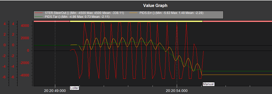
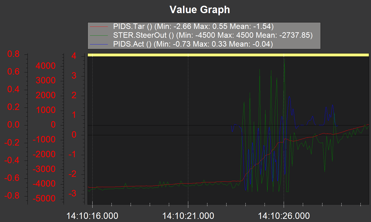
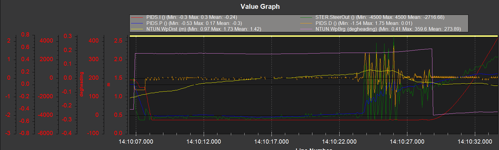
So for our prototype, my team of two has adopted this bogey board hull solution Announcing the Maker Boat Basic! developed largely by (i think) @nuballawalla (Daniel Carlson) & @rmackay9 (Randy Mackay) and are in the process of testing. Our status to date is that hull and propulsion are exactly what we want, but we can’t get the darn thing to “loiter”… but we are doing what we can, and taking/seeking input from this user group to sort out the issues …

We have a simple top works design and when the planets align will be posting to this forum, but prototype will be only a single buoy operated from a dedicated transmitter.

Next step, and we think its a big one, is the software / GUI / handset ability to direct and control multiple buoys from one control station / ipad / laptop, and we’ll really need help .

We can see applications for sailing, rowing, swimming, triathlon, water skiing, commercial shipping etc etc.

Trust this assists, and would be very pleased if you chose to collaborate.

You can also reach me on andrewRwilson62@gmail.com

@MoretonBayKiting,

OK great. Having SERVO1_REVERSED=1 should be fine. Another option is to swap two of the three wires connecting the ESC to the motor but it’s not important.

Thanks @rmackay9. Test last evening was unsuccessful as mode couldn’t change to loiter. I haven’t worked out why but suspect it was something to do with GPS signal. A test now, albeit with the FC out of the vessel and no motors connected, shows it moving to loiter as it did previously before. I’d like to analyse that log before launching in water again. Is there a position error, with direction to loiter station, in the log?

Peter, I’m prone to under estimate development required for most projects…witness the fact that I’m 3 weeks solidly into this 2 day (estimated) project! But, in principle I don’t think there is so much to do to go from a single BuoyBot rounding mark to a coordinated fleet each member of which will go to, and hold, it’s position if the system is given position of committee boat (or some reference), wind direction and course length (assuming a fixed geometry can be specified by these).

I’ve not yet tested loiter in the water. But behaviour, from the log, still seems very odd when the FC is simply sitting still. See for example the following (which shows SteeringOut, PIDS.Target and PIDS.Actual). I’m looking through code trying to work out what the inputs to the PIDS are and where they come from…

Hi all, the events that I’m talking about are on lakes or or just offshore and we’ll be on the water for about 4-6 hours maximum. 2 metre marks would the the exception, most of the time the marks 1.2 -1.5 metres.

The reason that I’m looking here is that the commercial solutions are out of most club’s price range and over the long term an open source solution will be better.

I see the following parts to a potential solution:

  • A GUI to calculate the mark coordinates and to send them and the instructions to the marks. Some instructions would be: move to x,y and loiter, move to x,y and drift, loiter in place, drift, etc
  • a platform to hold the mark which will be different based on the application
  • the electronics and software on the platform which will probably be basically the same for all applications

The GUI will be the easiest. A long time ago I wrote a little program that calculated mark locations based on a given course, wind direction and course length. The coordinates could be uploaded as waypoints into a GPS. This allowed my mark layer to lay a full trapezoid course within 15 minutes. He just used the go to option. Also, it displays the course in Google Earth if GE is running when you start the program. Here are the links to the program and a bit of documentation :
http://jpvm.org/Race%20Management/Peter%20van%20Muyden%20race%20management%20tools/Programs/GPSLoad%20readme.pdf http://jpvm.org/Race%20Management/Peter%20van%20Muyden%20race%20management%20tools/Programs/GPSLoad_install.exe

I suggest that you install it in a directory for which you have read write access. This is because there are a couple INI files included that allow you to configure the units and course configuration. The program works with or without a connected GPS. You can configure any course with up to 9 marks.

Overlaying the course on Google Earth is a powerful feature.

GE has a python API and is a very good tool for this.

Unlike the RC course, my course could cover 3KM. Will MavLink be able to cover that?

I know that 4 thruster Omni configurations are not supported, but can you use two pairs of thrusters for bigger platforms?

I’m still getting weird steering oscillations, even with the FC on my desk (but with good GPS). I’m interpreting NTUN.WpBrg and NTUN.WpDist as being the bearing and distance to the loiter station (way point). Is that the correct interpretation? If it is, then the throttle behaviour (not shown), which commences rising from zero when WpDist = 1 = LOIT_RADIUS, looks at least plausible. But with WpBrg changing very slowly (apart from the flip in display from 360 to 0), high amplitude & frequency steering oscillations commence and are driven by the derivative term in the PIDS. Gains are constant (ATC_STR_RATE_D = 0.2 =ATC_STR_RATE_P = ATC_STR_RATE_I; ATC_STR_RATE_FF = 0.05) so what is driving this behaviour? Is the steering speed available in the log? Log here: https://drive.google.com/file/d/1m_f2a37HCPCU3DdDingl8ix8GT6x1KSN/view?usp=sharing

Edit: The derivative term in the PID is _derivative += get_filt_D_alpha() * (derivative - _derivative); get_filt_D_alpha() is a low pass filter which is basically (dt/(dt+1/(2π * filt_D_hz))). I haven’t been able to find default values of dt and filt_D_hz. Any suggestions? (Even if this were the problem, I’d like to understand why a high frequency signal is being generated that needs filtering.) @rmackay9?