did you try to port it on ESP32-S3 ?
The hardware pin definition file for esp32 boards in: “ardupilot\libraries\AP_HAL_ESP32\boards” path.
@Riebers the answer also in the hardware pin definition file for each board.
@mr_byte31 I am trying, but not finish.
@Leon90 Can you share your project on Github so everyone can contribute and see the details?
Hi,
i built arducopter firmware for esp32 as follows:
./waf configure --board=esp32buzz
My AP_HAL_ESP32/boards/esp32buzz.h looks like following:
/*
* This file is free software: you can redistribute it and/or modify it
* under the terms of the GNU General Public License as published by the
* Free Software Foundation, either version 3 of the License, or
* (at your option) any later version.
*
* This file is distributed in the hope that it will be useful, but
* WITHOUT ANY WARRANTY; without even the implied warranty of
* MERCHANTABILITY or FITNESS FOR A PARTICULAR PURPOSE.
* See the GNU General Public License for more details.
*
* You should have received a copy of the GNU General Public License along
* with this program. If not, see <http://www.gnu.org/licenses/>.
*/
#pragma once
#define HAL_ESP32_BOARD_NAME "esp32-buzz"
// make sensor selection clearer
#define PROBE_IMU_I2C(driver, bus, addr, args...) ADD_BACKEND(AP_InertialSensor_##driver::probe(*this, GET_I2C_DEVICE(bus, addr), ##args))
#define PROBE_IMU_SPI(driver, devname, args...) ADD_BACKEND(AP_InertialSensor_##driver::probe(*this, hal.spi->get_device(devname), ##args))
#define PROBE_IMU_SPI2(driver, devname1, devname2, args...) ADD_BACKEND(AP_InertialSensor_##driver::probe(*this, hal.spi->get_device(devname1), hal.spi->get_device(devname2), ##args))
#define PROBE_BARO_I2C(driver, bus, addr, args...) ADD_BACKEND(AP_Baro_##driver::probe(*this, std::move(GET_I2C_DEVICE(bus, addr)), ##args))
#define PROBE_BARO_SPI(driver, devname, args...) ADD_BACKEND(AP_Baro_##driver::probe(*this, std::move(hal.spi->get_device(devname)), ##args))
#define PROBE_MAG_I2C(driver, bus, addr, args...) ADD_BACKEND(DRIVER_##driver, AP_Compass_##driver::probe(GET_I2C_DEVICE(bus, addr), ##args))
#define PROBE_MAG_SPI(driver, devname, args...) ADD_BACKEND(DRIVER_##driver, AP_Compass_##driver::probe(hal.spi->get_device(devname), ##args))
#define PROBE_MAG_IMU(driver, imudev, imu_instance, args...) ADD_BACKEND(DRIVER_##driver, AP_Compass_##driver::probe_##imudev(imu_instance, ##args))
#define PROBE_MAG_IMU_I2C(driver, imudev, bus, addr, args...) ADD_BACKEND(DRIVER_##driver, AP_Compass_##driver::probe_##imudev(GET_I2C_DEVICE(bus, addr), ##args))
//------------------------------------
// #define CONFIG_HAL_BOARD 12
// #define HAL_BOARD_ESP32 12
// INS choices:
// #define HAL_INS_DEFAULT HAL_INS_MPU9250_SPI
// #define HAL_INS_MPU9250_NAME "MPU9250"
// or this:
#define HAL_INS_DEFAULT HAL_INS_MPU6050_I2C
#define HAL_INS_MPU6050_BUS 0
#define HAL_INS_MPU6050_ADDR (0x68)
// BARO choices:
// #define HAL_BARO_DEFAULT HAL_BARO_BMP280_SPI
// #define HAL_BARO_BMP280_NAME "BMP280"
// or one of these:
// #define HAL_BARO_DEFAULT HAL_BARO_MS5837_I2C
// or: GPIO 34
#define HAL_BARO_ANALOG_PIN (6)
// MAG/COMPASS choices:
// or others:
// #define HAL_COMPASS_ICM20948_I2C_ADDR (0x68)
// #define HAL_COMPASS_AK09916_I2C_BUS 0
// #define HAL_COMPASS_AK09916_I2C_ADDR (0x0C)
// #define HAL_COMPASS_MAX_SENSORS 3
// IMU probing:
#define HAL_INS_PROBE_LIST PROBE_IMU_I2C(Invensensev2, 0, 0x68, ROTATION_YAW_270)
// MAG/COMPASS probing:
// #define HAL_MAG_PROBE_LIST ADD_BACKEND(DRIVER_ICM20948, AP_Compass_AK09916::probe_ICM20948_I2C(0, ROTATION_NONE));
// BARO probing:
// #define HAL_BARO_PROBE_LIST PROBE_BARO_I2C(BMP280, 0, 0x77)
// no airspeed sensor
#define AP_AIRSPEED_MS4525_ENABLED 0
#define AP_AIRSPEED_ENABLED 0
#define AP_AIRSPEED_ANALOG_ENABLED 0
#define AP_AIRSPEED_BACKEND_DEFAULT_ENABLED 0
// allow boot without a baro
#define HAL_BARO_ALLOW_INIT_NO_BARO 1
// ADC is available on lots of pints on the esp32, but adc2 cant co-exist with wifi we choose to allow ADC on :
// #define HAL_DISABLE_ADC_DRIVER 1
#define TRUE 1
#define HAL_USE_ADC TRUE
// the pin number, the gain/multiplier associated with it, the ardupilot name for the pin in parameter/s.
//
// two different pin numbering schemes, both are ok, but only one at a time:
#define HAL_ESP32_ADC_PINS_OPTION1 \
{ \
{ADC1_GPIO35_CHANNEL, 11, 1}, \
{ADC1_GPIO34_CHANNEL, 11, 2}, \
{ADC1_GPIO39_CHANNEL, 11, 3}, \
{ \
ADC1_GPIO36_CHANNEL, 11, 4 \
} \
}
#define HAL_ESP32_ADC_PINS_OPTION2 \
{ \
{ADC1_GPIO35_CHANNEL, 11, 35}, \
{ADC1_GPIO34_CHANNEL, 11, 34}, \
{ADC1_GPIO39_CHANNEL, 11, 39}, \
{ \
ADC1_GPIO36_CHANNEL, 11, 36 \
} \
}
// pick one:
// #define HAL_ESP32_ADC_PINS HAL_ESP32_ADC_PINS_OPTION1
#define HAL_ESP32_ADC_PINS HAL_ESP32_ADC_PINS_OPTION2
#define HAL_PROBE_EXTERNAL_I2C_COMPASSES 1
// #define HAL_INS_MPU9250_NAME "mpu9250"
// uncommenting one or more of these will give more console debug in certain areas.. ...
// ...however all teh extra printf's use a lot of stack, so best to limit yourself to only uncommenting one at a time
// #define STORAGEDEBUG 1
// #define SCHEDDEBUG 1
// #define FSDEBUG 1
// #define BUSDEBUG 1 //ok
// #define WIFIDEBUG 1 //uses a lot?
#define INS_TIMING_DEBUG 1 // define this to see all the imu-resets and temp resets and imu timing info on the console.
// #define HAL_INS_PROBE_LIST PROBE_IMU_SPI(Invensense, HAL_INS_MPU9250_NAME, ROTATION_NONE)
// #define HAL_INS_PROBE_LIST PROBE_IMU_SPI( Invensense, HAL_INS_MPU9250_NAME, ROTATION_ROLL_180)
#define HAL_BARO_PROBE_LIST PROBE_BARO_SPI(BMP280, "bmp280")
// 2 use udp, 1 use tcp... for udp,client needs to connect as UDPCL in missionplanner etc to 192.168.4.1 port 14550
#define HAL_ESP32_WIFI 1
// tip: if u are ok getting mavlink-over-tcp or mavlink-over-udp and want to disable mavlink-over-serial-usb
// then set ardupilot parameter SERIAL0_PROTOCOL = 0 and reboot.
// u also will/may want..
// LOG_BACKEND_TYPE 1
// LOG_DISARMED 1
// SERIAL0_PROTOCOL 0
// see boards.py
#ifndef ENABLE_HEAP
#define ENABLE_HEAP 1
#endif
#define WIFI_SSID "ardupilot123"
#define WIFI_PWD "ardupilot123"
// RCOUT which pins are used?
#define HAL_ESP32_RCOUT \
{ \
GPIO_NUM_25, GPIO_NUM_27, GPIO_NUM_33, GPIO_NUM_32 \
}
// GPIO_NUM_25, GPIO_NUM_27, GPIO_NUM_33, GPIO_NUM_32, GPIO_NUM_22, GPIO_NUM_21
// SPI BUS setup, including gpio, dma, etc
// note... we use 'vspi' for the bmp280 and mpu9250
#define HAL_ESP32_SPI_BUSES \
{ \
.host = VSPI_HOST, .dma_ch = 1, .mosi = GPIO_NUM_23, .miso = GPIO_NUM_19, .sclk = GPIO_NUM_18 \
}
// tip: VSPI_HOST is an alternative name for esp's SPI3
// #define HAL_ESP32_SPI_BUSES {}
// SPI per-device setup, including speeds, etc.
#define HAL_ESP32_SPI_DEVICES \
{.name = "bmp280", .bus = 0, .device = 0, .cs = GPIO_NUM_26, .mode = 3, .lspeed = 1 * MHZ, .hspeed = 1 * MHZ}, \
{ \
.name = "mpu9250", .bus = 0, .device = 1, .cs = GPIO_NUM_5, .mode = 0, .lspeed = 2 * MHZ, .hspeed = 8 * MHZ \
}
// #define HAL_ESP32_SPI_DEVICES {}
// I2C bus list
#define HAL_ESP32_I2C_BUSES \
{ \
.port = I2C_NUM_0, .sda = GPIO_NUM_22, .scl = GPIO_NUM_21, .speed = 100 * KHZ, .internal = true \
}
// #define HAL_ESP32_I2C_BUSES {} // using this embty block appears to cause crashes?
// rcin on what pin?
#define HAL_ESP32_RCIN GPIO_NUM_4
// HARDWARE UARTS
#define HAL_ESP32_UART_DEVICES \
{.port = UART_NUM_0, .rx = GPIO_NUM_3, .tx = GPIO_NUM_1}, { .port = UART_NUM_1, .rx = GPIO_NUM_16, .tx = GPIO_NUM_17 }
#define AP_FILESYSTEM_ESP32_ENABLED 1
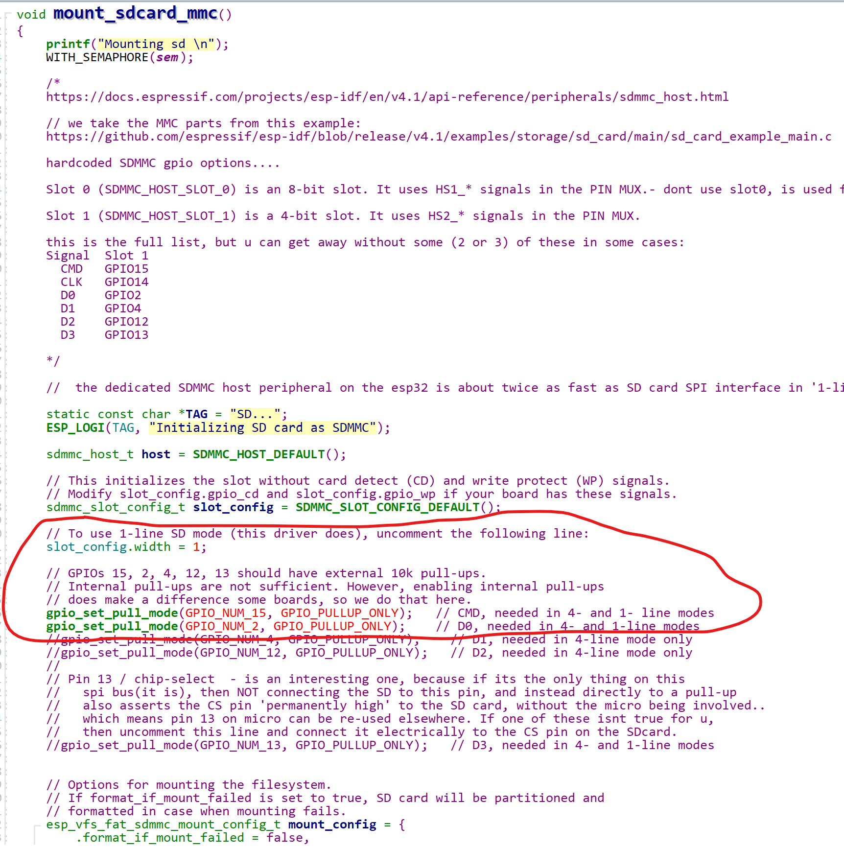
// Do u want to use mmc or spi mode for the sd card, this is board specific ,
// as mmc uses specific pins but is quicker,
#define HAL_ESP32_SDMMC 1
// and spi is more flexible pinouts.... dont forget vspi/hspi should be selected to NOT conflict with SPI_BUSES above
// #define HAL_ESP32_SDSPI {.host=VSPI_HOST, .dma_ch=2, .mosi=GPIO_NUM_2, .miso=GPIO_NUM_15, .sclk=GPIO_NUM_14, .cs=GPIO_NUM_21}
#define HAL_ESP32_SDCARD 1
#define LOGGER_MAVLINK_SUPPORT 1
#define HAL_BOARD_LOG_DIRECTORY "/SDCARD/APM/LOGS"
#define HAL_BOARD_TERRAIN_DIRECTORY "/SDCARD/APM/TERRAIN"
#define HAL_BOARD_STORAGE_DIRECTORY "/SDCARD/APM/STORAGE"
// this becomes the default value for the ardupilot param LOG_BACKEND_TYPE, which most ppl want to be 1, for log-to-flash
// setting to 2 means log-over-mavlink to a companion computer etc.
#define HAL_LOGGING_BACKENDS_DEFAULT 1
#define HAL_ESP32_RMT_RX_PIN_NUMBER 4
I have connected an mpu6050 sensor on i2c on gpio 22 and 21 for sda and scl.
When i change into build/esp32buzz/esp-idf-build and run
ninja monitor
I got the following output:
] overshoot2 35�ets Jun  8 2016 00:22:57

rst:0x1 (POWERON_RESET),boot:0x13 (SPI_FAST_FLASH_BOOT)
configsip: 0, SPIWP:0xee
clk_drv:0x00,q_drv:0x00,d_drv:0x00,cs0_drv:0x00,hd_drv:0x00,wp_drv:0x00
mode:DIO, clock div:1
load:0x3fff0030,len:4976
load:0x40078000,len:15300
ho 0 tail 12 room 4
load:0x40080400,len:3776
0x40080400: _init at ??:?

entry 0x40080620
I (579) cpu_start: Multicore app
I (579) cpu_start: Pro cpu up.
I (580) cpu_start: Starting app cpu, entry point is 0x4008564c
0x4008564c: call_start_cpu1 at /home/max/Projects/esp-idf/esp-idfv4.4/esp-idf/components/esp_system/port/cpu_start.c:151

I (0) cpu_start: App cpu up.
I (597) cpu_start: Pro cpu start user code
I (597) cpu_start: cpu freq: 240000000
I (597) cpu_start: Application information:
I (602) cpu_start: ELF file SHA256:  951eb529c9db72b9...
I (608) cpu_start: ESP-IDF:          v4.4.6-98-g5f257494c5
I (614) cpu_start: Min chip rev:     v0.0
I (619) cpu_start: Max chip rev:     v3.99
I (624) cpu_start: Chip rev:         v1.0
I (628) heap_init: Initializing. RAM available for dynamic allocation:
I (636) heap_init: At 3FFAE6E0 len 00001920 (6 KiB): DRAM
I (642) heap_init: At 3FFC61E8 len 00019E18 (103 KiB): DRAM
I (648) heap_init: At 3FFE0440 len 00003AE0 (14 KiB): D/IRAM
I (654) heap_init: At 3FFE4350 len 0001BCB0 (111 KiB): D/IRAM
I (661) heap_init: At 40096378 len 00009C88 (39 KiB): IRAM
I (667) spi_flash: detected chip: generic
I (672) spi_flash: flash io: qio
I (687) esp_core_dump_uart: Init core dump to UART
I (687) cpu_start: Starting scheduler on PRO CPU.
I (0) cpu_start: Starting scheduler on APP CPU.
virtual void ESP32::Scheduler::init():70 running with CONFIG_FREERTOS_HZ=500
OK created task _main_thread
AnalogIn: eFuse Two Point: NOT supported
AnalogIn: eFuse Vref: Supported
OK created task _timer_thread
oooooooooooooooooooooooooooooooooooooooooooooooooooooooooooooooooooooo
OK created task _rcout_thread
RCOutput::init() - channels available: 4
oooooooooooooooooooooooooooooooooooooooooooooooooooooooooooooooooooooo
OK created task _rcin_thread
OK created task _uar
                    K���5


Init ArduCopter V4.5.0-dev (65be0bd1)

Free RAM: 110592
load_all took 862us
I (830) wifi:wifi driver task: 3ffd9998, prio:23, stack:6656, core=0
I (830) system_api: Base MAC address is not set
I (830) system_api: read default base MAC address from EFUSE
I (836) wifi:wifi firmware version: d9959e6
I (840) wifi:wifi certification version: v7.0
I (844) wifi:config NVS flash: disabled
I (848) wifi:config nano formating: disabled
I (852) wifi:Init data frame dynamic rx buffer num: 16
I (856) wifi:Init management frame dynamic rx buffer num: 16
I (862) wifi:Init management short buffer num: 32
I (866) wifi:Init dynamic tx buffer num: 16
I (870) wifi:Init static rx buffer size: 1600
I (874) wifi:Init static rx buffer num: 2
I (878) wifi:Init dynamic rx buffer num: 16
I (882) wifi_init: tcpip mbox: 32
I (886) wifi_init: udp mbox: 6
I (890) wifi_init: tcp mbox: 6
I (894) wifi_init: tcp tx win: 5744
I (898) wifi_init: tcp rx win: 5744
I (902) wifi_init: tcp mss: 1436
I (906) wifi_init: WiFi RX IRAM OP enabled
I (1238) phy_init: phy_version 4771,450c73b,Aug 16 2023,11:03:10
I (1306) wifi:mode : softAP (a6:cf:12:25:0a:44)
I (1308) wifi:Total power save buffer number: 8
I (1308) wifi:Init max length of beacon: 752/752
I (1308) wifi:Init max length of beacon: 752/752
OK created task _wifi_thread
AnalogIn: adding ardupin:255-> which is adc1_offset:-1
AnalogIn: channel:0 created but using delayed adc and gpio pin configuration
spi device constructed SPI:bmp280:0:0
AP_Logger_File: buffer size=16384
E (1816) sdmmc_req: sdmmc_host_wait_for_event returned 0x107
E (1822) sdmmc_common: sdmmc_init_ocr: send_op_cond (1) returned 0x107
E (1822) vfs_fat_sdmmc: sdmmc_card_init failed (0x107).
sdcard is not mounted
No Compass backends available
Init Gyro[timing] overshoot2 5993
[timing] overshoot2 6000
[timing] overshoot2 6079
[timing] overshoot2 5921
*[timing] overshoot2 112
[timing] overshoot2 7888
[timing] overshoot2 6000
[timing] overshoot2 6000
[timing] overshoot2 6000
Followed by many of these [timing] overshoot 6000 messages.
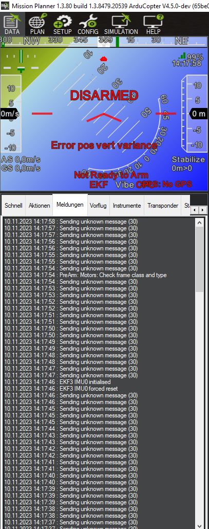
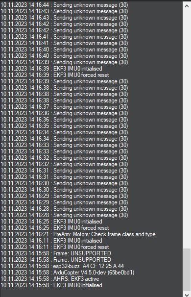
I can connect with mission planner but get error messages as well.
Does anyone know where the problem is or why i get these strange timing errors?
Thanks and have a good one
1 Like
Ah sorry i forgot!
Here are screenshots when connecting with mission planner.
@Leon90 did you see something before?
Thanks for your help!
@mr_byte31 maybe after the gps funtion testing finish.
@Riebers you can try to use “.soft=ture” in HAL_ESP32_I2C_BUSES define struct in esp32buzz.h, and change the “businfo[i].sw_handle.speed = I2C_SPEED_FAST” to “businfo[i].sw_handle.speed = I2C_SPEED_HIGH” in I2CDevice.cpp, maybe this can slove the timing problem.
@Riebers the (30) is the id of the unknown message, and it is the MSG_FENCE_STATUS, this part is in the GCS_Common.cpp;
This is a similar problem: Getting "Sending unknown message (50) " continously on 4.3.0 custom build · Issue #21817 · ArduPilot/ardupilot · GitHub
Hope it can help you.
@Leon90 one info…how i can connect SDCard on Esp32 with Arducopter ?
@skimans You can get some info in the SDCard driver sours code file for esp32 platform:
1 Like
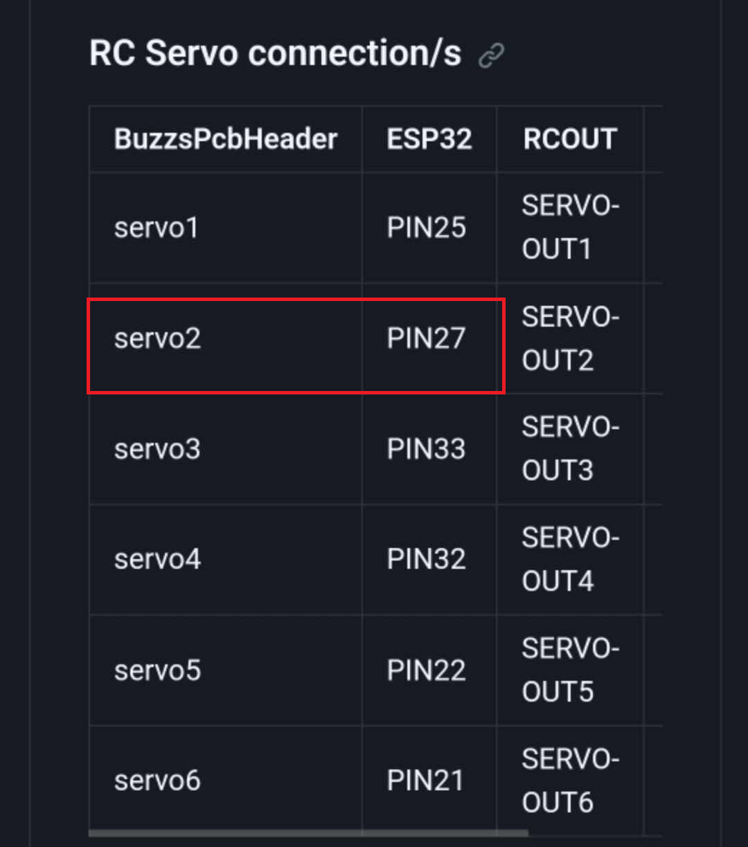
@Leon the motor 2 use same pin 27 of SCL.
where is the error ??
but wich PINs i must use for Motor1,2,3,4 ?
thanks much
@skimans If you talk about my firmware I send to you before, the motor pin is:
{ GPIO_NUM_4, GPIO_NUM_12, GPIO_NUM_14, GPIO_NUM_2 }
1 Like
Some update for firefly:
1.Can`t do the GPS testing, because the motor magnet makes the mag sensor crazy.
2.Outdoor fly testing:

3.Add a motor self-testing step when power on.

3 Likes
@Leon90 Excelent job!!
GPS module (and Mag) must to be far from board ESP32 becouse there are noises of signal.
Usually i put GPS (and Mag) in high position (min 8 cm from the board).
Best gps module are Beitian 880 that include inside the Mag.
Do you have install also Baro…right ?
Finally i have installed your firmware and i have two question:
- wich pins do you use for TX and RX of GPS ?
- wich pin for RX receiver ?
i connect pin motors but the test motor not work:
{ GPIO_NUM_4, GPIO_NUM_12, GPIO_NUM_14, GPIO_NUM_2 }
i have connected:
motor 1 = GPIO 4
motor 2 = GPIO 12
motor 3 = GPIO 14
motor 4 = GPIO 2
thanks much
@skimans
1、U0TXD and U0RXD is use for GPS, to use this, you need to change serial0 protocol from Mavlink to GPS by QGC or MP, notice that, after this setting, the serial0 can`t use to communication with QGC or MP.
2、RX receiver pin is IO33.
3、The motor self-testing is a new add function.
@Leon90 but RX receiver is PPM or SBUS ?
becouse not work calibration radio and not work motor test for check if motors are OK.
It’s strange becouse i have connect the 4 motors in correct pins.
Until now i dont connect GPS and compass, becouse i want check if work with only gyro/acc.
@skimans I use a small size receiver named AC900, it is SBUS signal, but look the RC driver in source code, the PPM signal should be work too.
Hope this can help you:
This is the manual for AC900 receiver: AC900 DUAL-BAND RX (faiusrd.com)
1 Like
@Riebers do you have solved ?