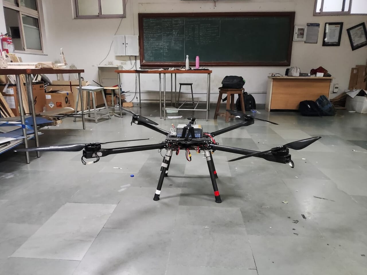
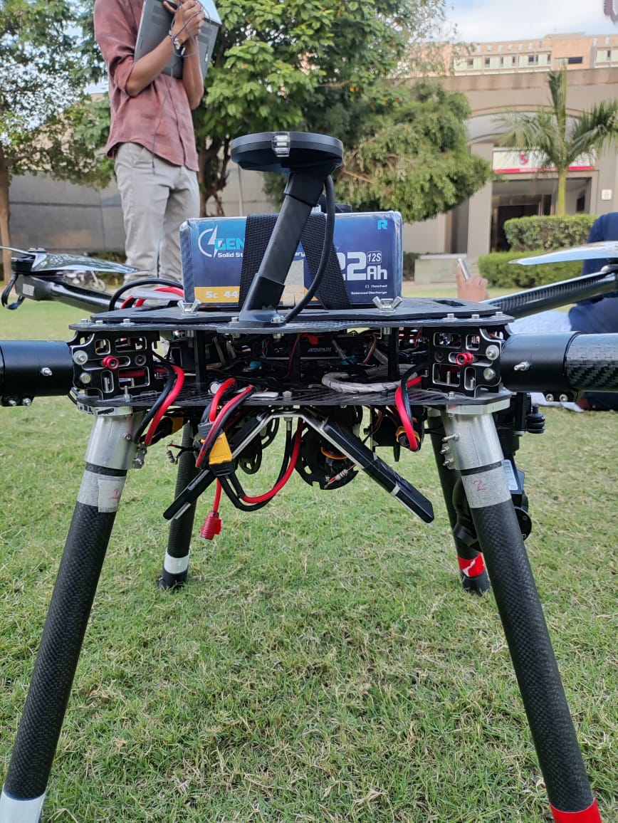
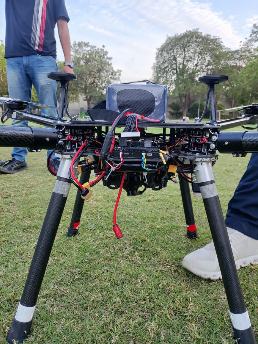
We made a Quadcopter of 15kgs with propulsion system of T-motor antigravity MN8014 100kv with T-motor fame 80A V2.0 ESC and T-motor G 30*10.5 inch propeller and 22000mAh 12S li-ion battery.
Initially, we calibrated the Pixhawk’s IMU temperature and conducted a test flight.We
autotuned our airplane after adjusting
the notch filter and motor thrust scaling.
We repeatedly experimented with several adjustments in Autotune, such as0.05,0.075, and0.1, however each time the pitch axis was set too jerkily, the roll axis was always correctly tuned. Assuming that the damper was the source of the issue, we changed the damper to minimize it, but the outcome remained the same—roll autotunes, but pitch doesn’t. At that point, we made the decision to manually adjust the pitch axis. After doing so, our quadcopter reached at a speed of 18 m/s without estimating wind speed; but, the following day, it began to wobble, and it has continued to do so. We had the quadcopter configured with a notch frequency of 31 Hz at the time, but after replacing the new motor in the nose direction, we obtained a notch frequency of 68 Hz. As a result, we have since configured the quadcopter with two notch frequencies, 31 and 68 Hz.We tuned the aircraft once more, and after autotuning, we set up wind speed estimation with
EK3_DRAG_COEFF_X 516.85
EK3_DRAG_COEFF_Y 544
EK3_DRAG_MCOEFF 0.4.
As a result, our primary issue at the moment is that it wobbles in both windy and calm conditions.
I used the .bin file that you provided to quickly build the ArduPilot Methodic Configurator intermediate parameter files: neel_chhatrala.zip (271.0 KB)
I opened the directory in ArduPilot Methodic Configurator and could see that almost all parameters have default values and have not been configured!
Use the .zip file, extract it to a directory, start the software and open that directory. Then use the software to configure the vehicle.
Stop wasting your time trying to find shortcuts, there are none! Add properreason changed messages for EVERY parameter that you change.
Just configure your vehicle properly.
PS: the log file shows that you did not conduct a IMU temperature calibration.
The software will modify the intermediate parameter files for you. The next time you post a support question include a .zip file with the edited files (including the .param, .json, .jpg and .png files)
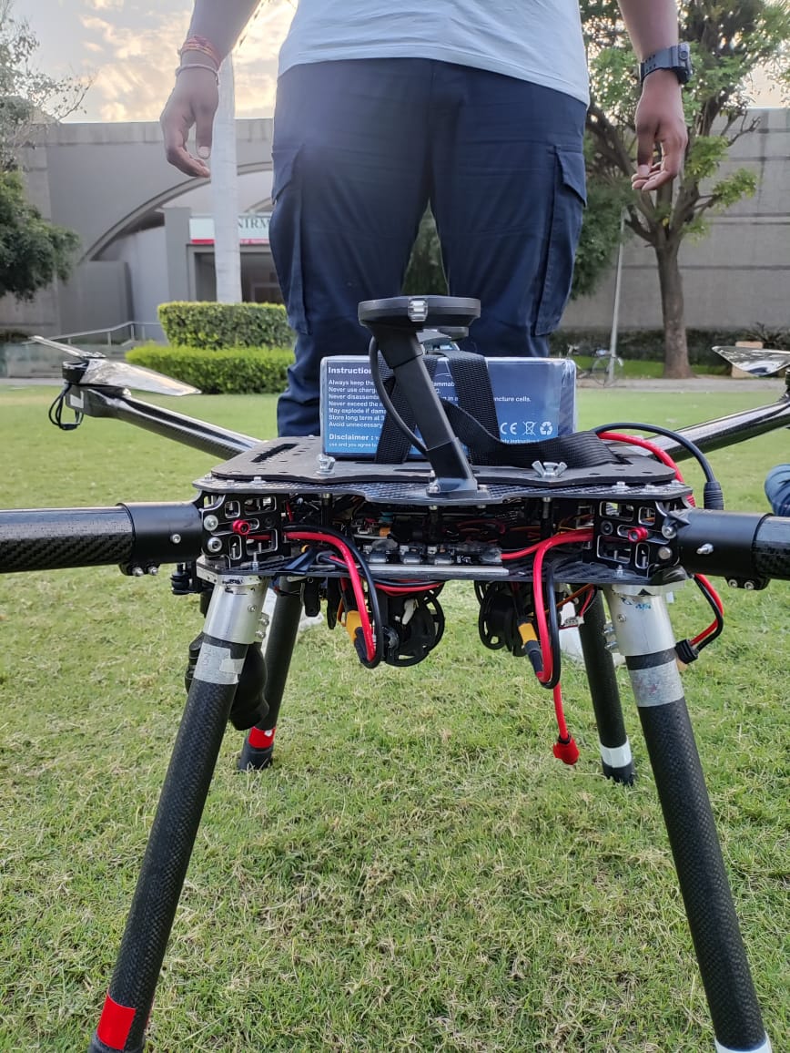
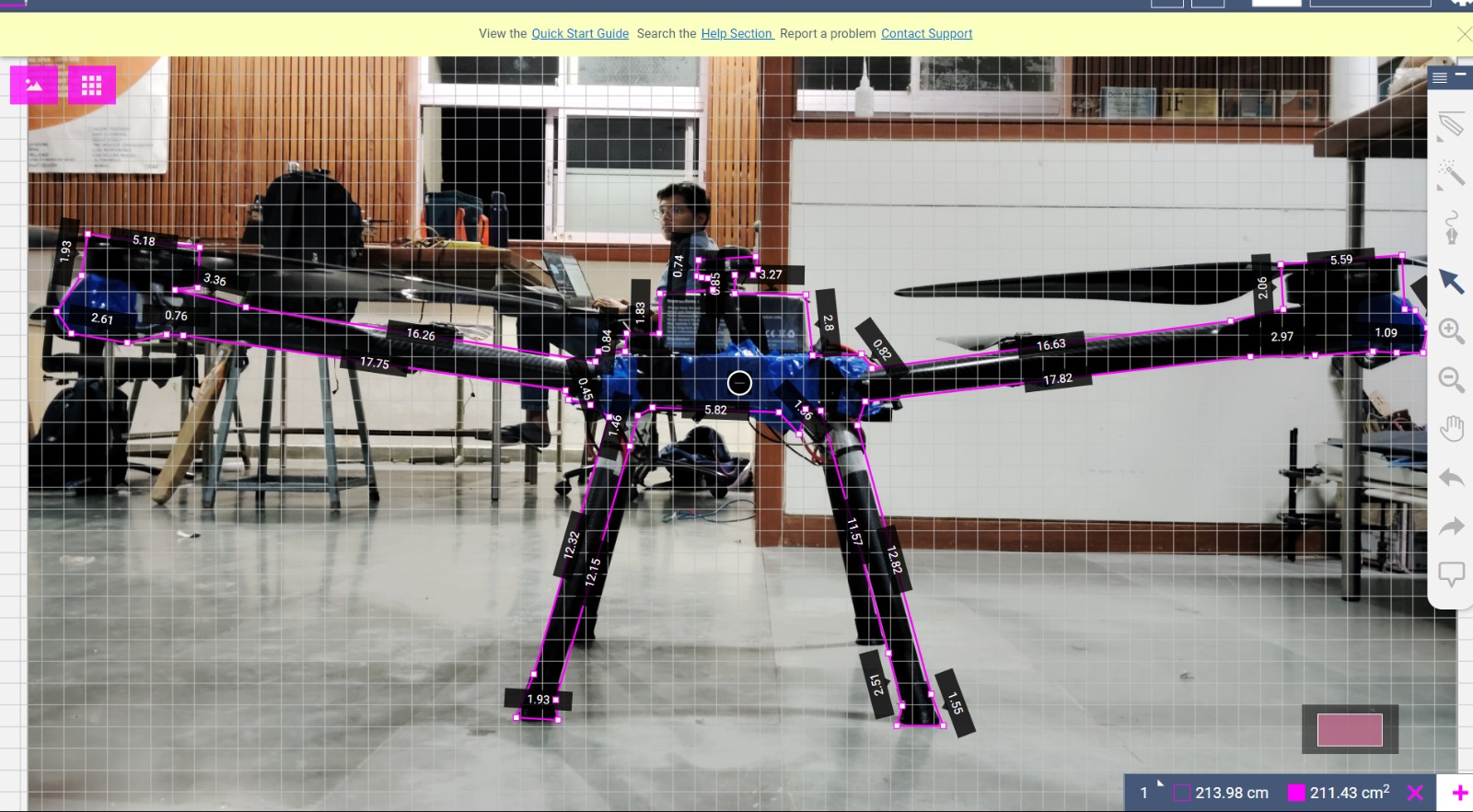
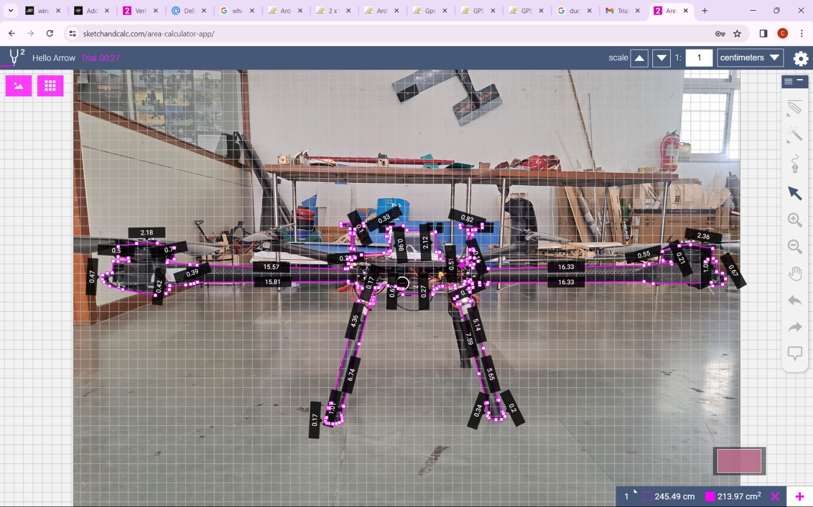
According to this website, which is the product page of the battery you are using I believe, the battery’s dimensions are 195x77x134 mm. The shortest side being 77mm or 7.7cm means that you didn’t scale the images correctly. In the images you took the measurements from, it looks like the shortest side of your battery is measured as 2.8 cm (side) or 2.12 cm (front).
So scaled correctly your frontal area and BCOEF_X would be
213.97 cm² * (7.7 cm / 2.12 cm)² = 2822.69 cm² → BCOEF_X = 15kg / 0.2823 m² = 53.13
and your side area and BCOEF_Y would be
211.43 cm² * (7.7 cm / 2.8 cm)² = 1598.94 cm² → BCOEF_Y = 15kg / 0.1599 m² = 93.81
Also I have two more things to point out:
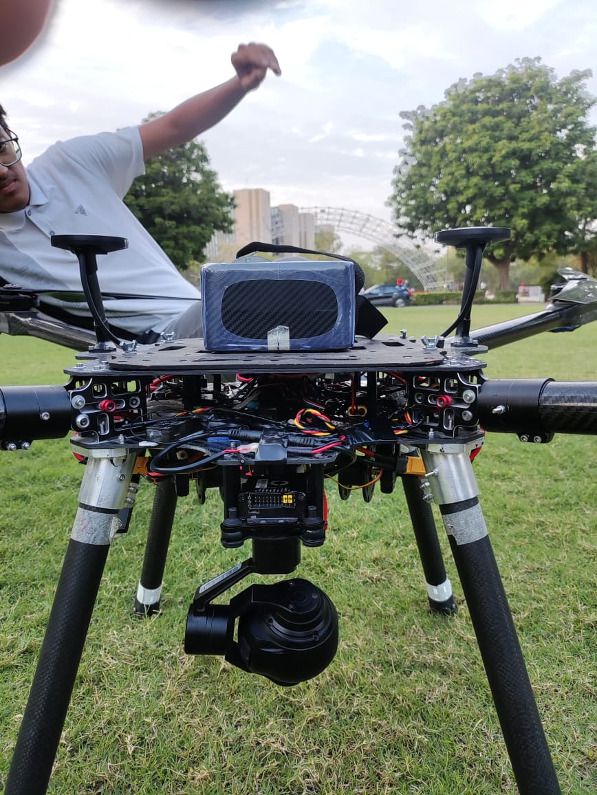
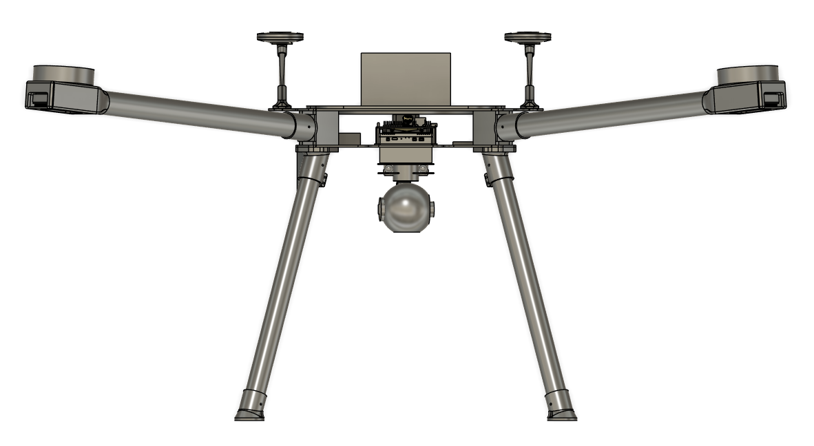
you didn’t fotograph and measure the camera and gimbal, which will influence the cross section measurements.
you took the foto from quite a close distance, which adds lots of perspective distortion, which in turn impacts the accuracy of the measurements greatly.
Due to the perspective distortion I mentioned, the CAD model probably is closer to the truth than the images, even after scaling. My scaling likely wasn’t the most accurate either, since I am not sure if 2.12 cm is for the whole battery or not.
930 cm² would result in a BCOEF = 161, which is also plausible.
Btw, are camera and gimbal included in the 930 cm² ?
The question now is why you didn’t take the values from the CAD model in the first place…
Yes the camera and gimbal are included
The reason i didn’t take it earlier as its too low that i thought of as its last year modified frame i thought it would have almost same area
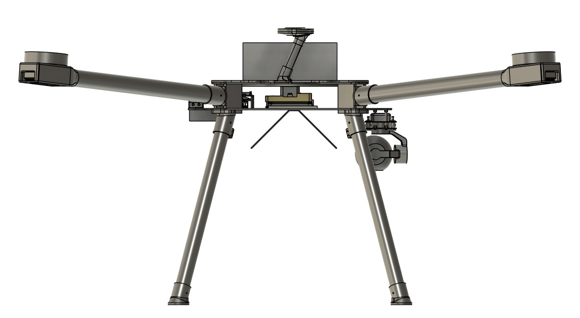
I took the CAD model you shared in the top post and this is what I did/found:
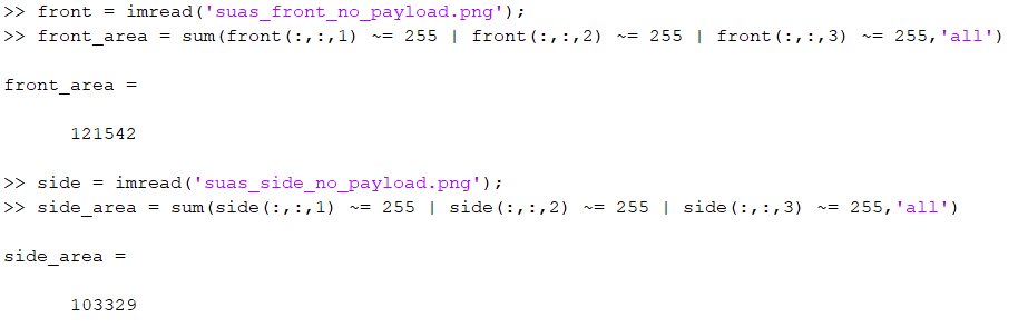
First I excluded the winch assembly, since technically you never mentioned it. Then I scaled it, so that 1 pixel is exactly 1 mm² (± 1%), then I took a screenshot and counted all non-white pixels.