POWER_STATUS is really interesting! The overall sanctity of the system can be governed.
I wonder how will the Helical antenna will perform if it is tilted by 90 degrees in case of tailsitters!
POWER_STATUS is really interesting! The overall sanctity of the system can be governed.
I wonder how will the Helical antenna will perform if it is tilted by 90 degrees in case of tailsitters!
Great work Tridge. Thank you.
I’ve paired my F9s with Tallysman TWI7972 antenna and seeing great results. Yeah the antenna is more expensive than the receiver. We use this configuration for our PPK based ground control points.
15 seconds is too much in our application, it looses fix and we have to restart the job. With str2str never looses it, happy with it.
This is very valuable testing. In fact, let’s crowd source this so we can continue to compile more hardware performance. Is there a wiki we could use to track the performance vs equipment matrix?
Jeff
To enable Galileo on ublox GPS there is this unmerged PR AP_GPS_UBLOX: Fix GALILEO auto configuration by giacomo892 · Pull Request #13853 · ArduPilot/ardupilot · GitHub
I use it on my Copters with M8N with success.
yep ! I know, I am trying to get somebody more qualified than me to review this. It would be good to have it
Very interesting results!
Silly question - do all of these also include a compass? The Holybro site doesn’t refer to a compass built in, but does identify SDA / SCL pins on the connector.
Is there a local (Australia) source for Holybro that you’re aware of?
The holybro ones do have an IST8310 compass builtin on I2C. Sorry for not mentioning that.
Thank you! It would be very useful for those living in Europe! 
Really good review. Thanks
Hello, I know this discussion is two years old but my comments might benefit some users. This test setup is not valid as the antennas are very close to each other (under 20cm which is a wavelenght at GPS L1). This means that they will couple to each other and affect their radiation patterns. Ideally, you need more space between the antennas (40 cm ++). Also the patch antennas need to be used with a 10 cm (diameter) ground plane directly under them. This is the only way to get the best performance (limit multipath and optimise radiating efficiency). Conclusions from sush a setup can be very misleading because this is not a way a GNSS antenna should be implemented and used.
thanks Julien. If I redo these tests I will get a bigger table to allow them to be spaced out more and do some testing with and without a ground plane.
On the ground plane, most users of these modules don’t use a ground plane, which is one of the reasons I generally recommend the helicals which don’t need a ground plane.
Would a 10cm diameter aluminum foil under the patch antenna GPS’ work as a ground plane? Or does the ground plane need to be connected/grounded to the antenna/gps itself as well?
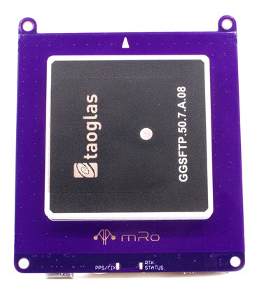
And a patch antenna is the classic one we see here, the squared ones, yes?
@ohitstarik
This may provide some answers:
Yes aluminium foil will work. Everything that reflect the electromagnetic waves. Same rules for every patches, They need a half wavelength ground plane, square or round.
The patch you are showing is a single feed patch which mean his circular polarization caracteristics will be lost on the edges of the bandwidth and the phase of the signal will be affected. Not a good choice for modern RTK solution.
That’s correct if they can work with the height of the antenna. Helical antennas are good antennas, but most of the ones on the market don’t have a filter at the front end of the amplifier which make them very vulnerable to interfering signal. Tallysman helical antennas will offer a better protection.
The ground plane need to be as close as possible of the patch, not necessarily DC connected but better if it is. The configuration should be as symmetric as possible.
Thanks for the data @tridge.
Just one help, Can you explain how exactly did you obtain the CEP & HEP values step by step, from median to the exact value.
Would be helpful as I am trying to do the same.
Hey @tridge !
Very nice round up, I love to see a lot of data! In my lab we’ve been enjoying using F9P receivers, but I am now looking for something more “low cost”. I was wondering if you had any opinion on M10 vs M9N?
M10 receivers (MAX-M10S and SAM-M10Q) have a 1.5m CEP vs 2m CEP for M9N (according to Ublox’s specsheets). But the M10’s update rate is much lower due to the lower clock speeds and ~3x lower power consumption. I saw your commit to change the M10 config to ditch the Glonass constellation to achieve the minimum desired 5 Hz, but have you tried to configurate the “high performance mode” of the M10? It increases the clock speed and can supposedly achieve 10 Hz with all 4 constellations (more info about high performance mode in the “Integration manual” of the MAX-M10S or SAM-M10Q.
EDIT: What crazy is the even lower power UBX-M10050-KB chip can achieve 1.5m CEP with all 4 concurrent constellations at 10 Hz (according to the specsheet). Have you had any experience with this receiver?
Power issues are hard to diagnose. Too many factors. By far 0.2V difference around nominal rated voltage should be accepted as minimal expected resilience. Other than this, is either bad design or bad power supply (my opinionated, well, opinion).
Starting from own module power strategies and the kind of support needed (i.e. inrush currents) and how good/bad module’s own support circuit is. On top of this, the ability (or not) of FC power modules to cope with requirements, including inrush current. FC switching power modules uses relatively small µF filter capacitors, so expect ripple and noise from them as more you pull current from it.
Many times I guess ‘low voltage’ being more a general sympton than root cause of problems like GPS issues, with things like bad ripple and noise being more important. A good start test/workaround is adding a large capacitor as near as possible to GPS Vcc/Gnd.