Yes, I will use the signal strenght to filter down this error, since new release, this information is quite usefull. Initial test demonstrate it can be corrected down to 5cm , depending on surface refectivity.
1 Like
That’s awesome, thank you
1 Like
Siya
I used the firmware link from David Ardis yesterday to upgrade the firmware based on the posts yesterday (to get it to work with Pixhawk 2.1 without having to rebuild Pixhawk code). I couldn’t find the firmware anywhere on the Benewake website and this post seemed to be the only place to find it.
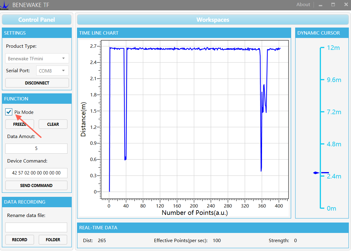
The unit still seems to report distance correctly when I connect to the GUI and click on on “Pix Mode”.
Do I now need to update to a different firmware?
I have not had a chance to try it in my copter yet.
Thanks
Hi, David. May I know why you need to upgrade firmware of TFmini? Because your current firmware can not be used ?
Usually, it’s no need to do firmware upgrade, you can realised your application by using the “TF GUI” in the TFmini information pack (I’ve listed the Googledrive link above). Pls check the below picture. If you select pix mode, then all the TFmini changed to Pix packet format output.
Pls try and let me know. If it still not work, I’ll ask engineer to help
Hi, Michael.
You mentioned "The unit still seems to report distance correctly when I connect to the GUI and click on on “Pix Mode”. " So, it means you’ve modified the configuration successfully, you can close the windows display directly, and connect to Pixhawk, then you can use it.
No need to upgrade firmware.
Siya
In a prevoius post you asked me to delete the link to the firmware on the 3DXR website (which I have done) you also mentioned that this firmware “will caused damage of your TFmini” unfortunately this is the firmware I have installed.
This is the reason why I have asked for the original firmware.
David Ardis
I installed this firmware from your earlier post, and in my case it looks like it is ok. It all uploaded correctly using the firmware updater programme that was in your post then I opened the TF GUI (in Siya’s later post) and it connects and reads ok. So I’m not sure how it can damage some boards - unless some of hardware is different.
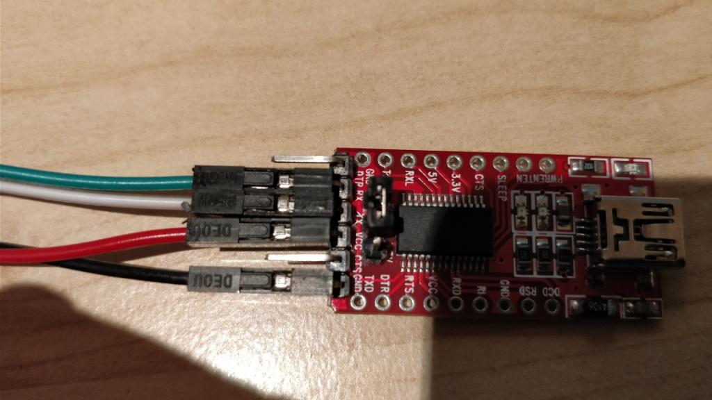
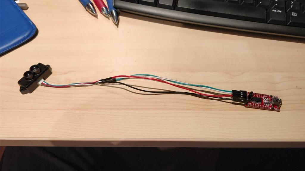
I connected to the TFmini with a custom cable I made from the one that came with the TFmini and using a FTDI232 adaptor I had lying around. (The custom cable looks a lot like the one you made)
For info I bought my unit from the 3DXR.co.uk website about a week ago.
I’ll post up some photos/screenshots shortly.
Further to my previous post, the reason I updated the firmware was because all of the other post I’ve seen on this subject initially said that the Arducopter lightware driver had to be slightly modified, and then Arducopter code had to be rebuilt. After toiling for a bit it became obvious this was above my head, but in the meantime various posts popped up and @ppoirier kindly advised that that the Arducopter driver no longer needed to be changed, and that instead the TFmini would work out of the box (with new TFmini firmware). Please see:
So to be in my clear in my case I THOUGHT:
- Arducopter firmware does not need to be modified
- TFmini firmware needed to be updated
I have not yet connected the TFmini to arducopter because I can’t find a pinout of Serial 5 on the Pixhawk 2.1 and all my other telemetry ports are in use. And before someone links to the Pixhawk 2.1 pinout manual, this shows the pin numbers in a table, but not a diagram of which pins these are. The diagram in this manual shows the pins but they are not numbered. Anyway that is slightly off topic, but if anyone knows this info it will be greatly appreciated!
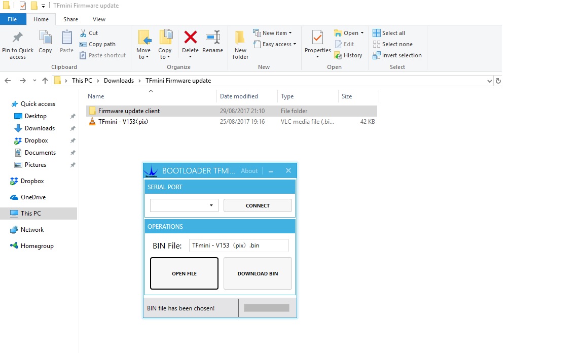
This is what I used to update firmware:
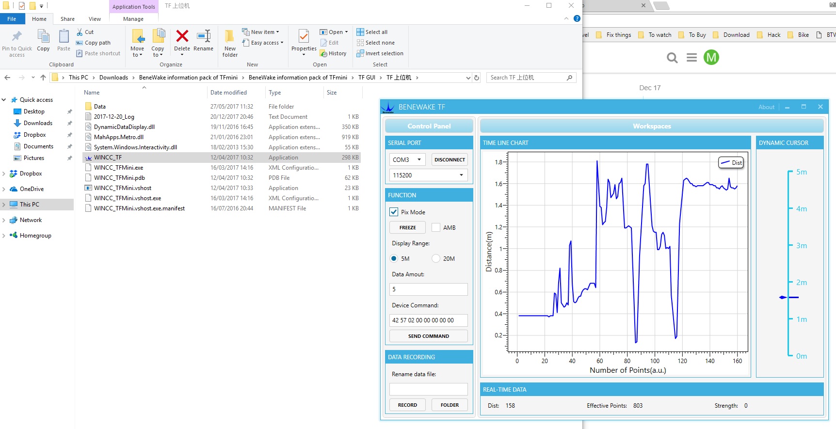
Then this is what I get when I connect to the GUI provided by Siya in an earlier post:
I’m not suggesting anyone should do this as @Siya said that the 3DXR firmware I installed will damage the board. But in my case it works although I still need to figure out how to connect it to Serial 5 of the Pixhawk 2.1.
If I have made a mistake on what I needed to do hopefully someone will chip in and offer a bit of clarity.
How I connected up to my PC:
@Michael_Brooks I think this is what you are looking for:
http://www.hex.aero/wp-content/uploads/2016/07/DRS_Pixhawk-2-17th-march-2016.pdf
Feed the power from a BEC like @ardisd david did
Hi,
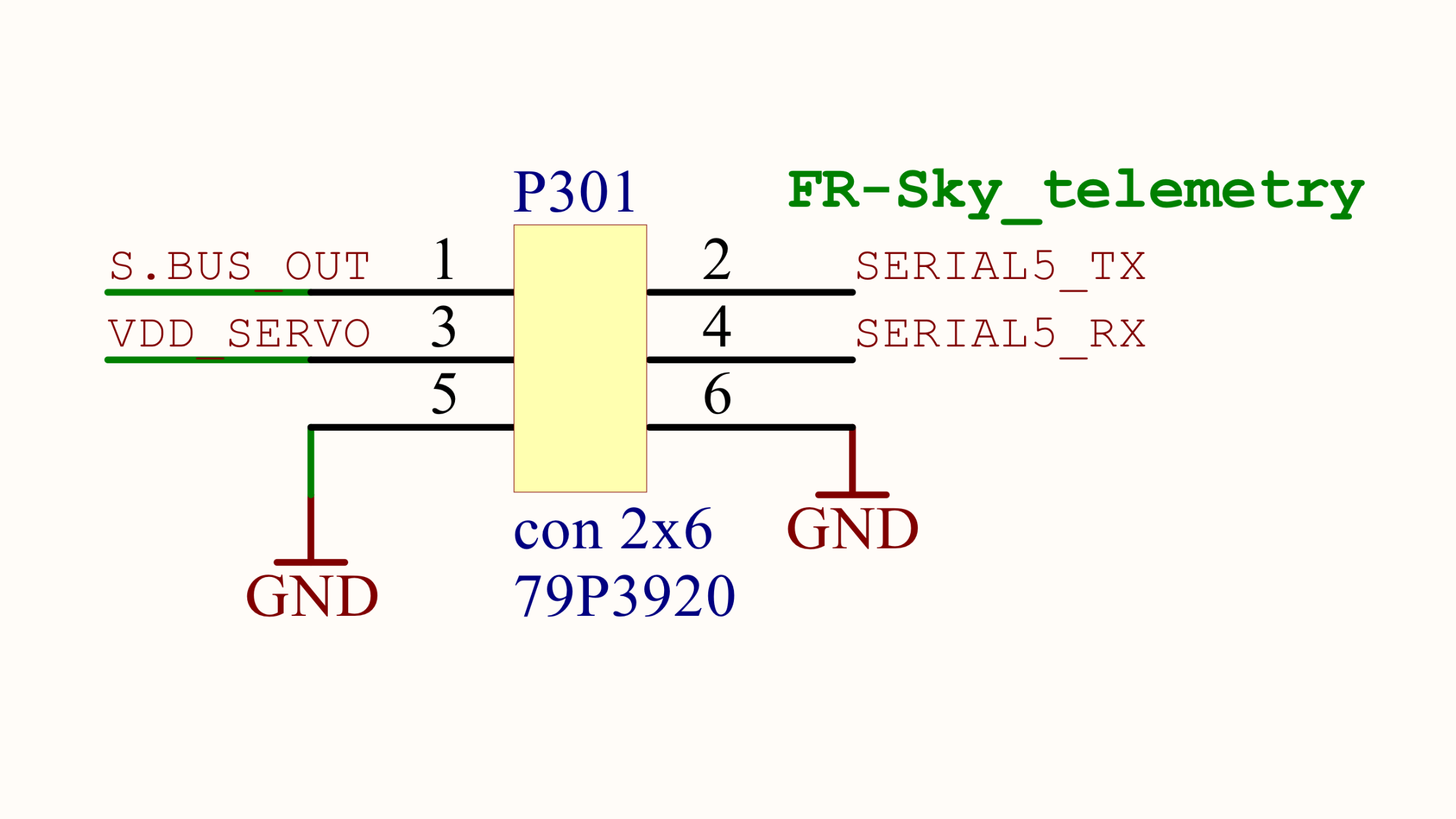
I think I can connect to serial 5 with the cable I have used to update the firmware (shown in my post above) because serial 5 has pin headers, unlike the other serial ports. The only complication might be that the grounds of the serial 5 and servo connectors might not be common (I’m not sure). If they are commoned I can probably just plug the red wire into the +5v servo rail and the other wires into the serial 5 pin headers. If the grounds are not common I can modify the cable to be more like David’s with two ground connections.
The issue I have is that the picture in the manual does not label the pin numbers. It just says Serial 5: See below:
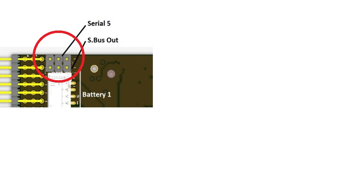
Actually thinking about it, I think I can see a tiny “-” symbol on the pin to the far right. This must mean that the other two pins are RX and TX (and I will not damage anything if I get them the wrong way around). So maybe I can just figure it out with trial and error?
I don’t think @ardisd is using a BEC, I think he is plugging the servo connector into the servo rail? (He can probably correct me here if I am wrong)!
Thanks
Cant really help you on the PX2, I dont have one, but I would use a known working port for tests.
I strongly recommend that you use a clean source of power like a dedicated BEC with filtering.
Servo rails is not a good place to be when you are using this type of device.
Michael
Hope this helps
I am using a 5v BEC to power the servo rail as its not power as standard on the Pixhawk 2.1. I assume that your speed controllers don’t have internal BEC’s if you are not sure remove the red wires from the speed controllers and as mentioned in an earlier post tie all the grounds together.
David Ardis
1 Like
David & ppoirier,
Yes that is really helpful. Exactly what I’ve been looking for. I’m starting to think I should’ve gone for standard pixhawk as there’s more documentation around. I went straight to 2.1 from APM 2.6!
Right so I understand now. Servo rail not independently powered and (David) you are actually using BEC. I do have a clean filtered power supply available already so I’ll modify the cable.
And (ppoirier) I take your point about using a working telemetry port first. Makes sense if I run into problems for fault finding.
Thanks again for your help.
I have written a blog on how to connect I2C using an Adruino:
1 Like
It`s very useful.Thank you very much.
Does anyone know the connector type used in the 4 pin socket on the Benewake TF mini LiDAR please? I mislaid my cable and need to replace it.
Cheers,
A
Hi,the connector type used in the 4 pin socket on the Benewake is GH1.25-4p.
Hi,the connector type used in the 4 pin socket on the Benewake is GH1.25-4p.
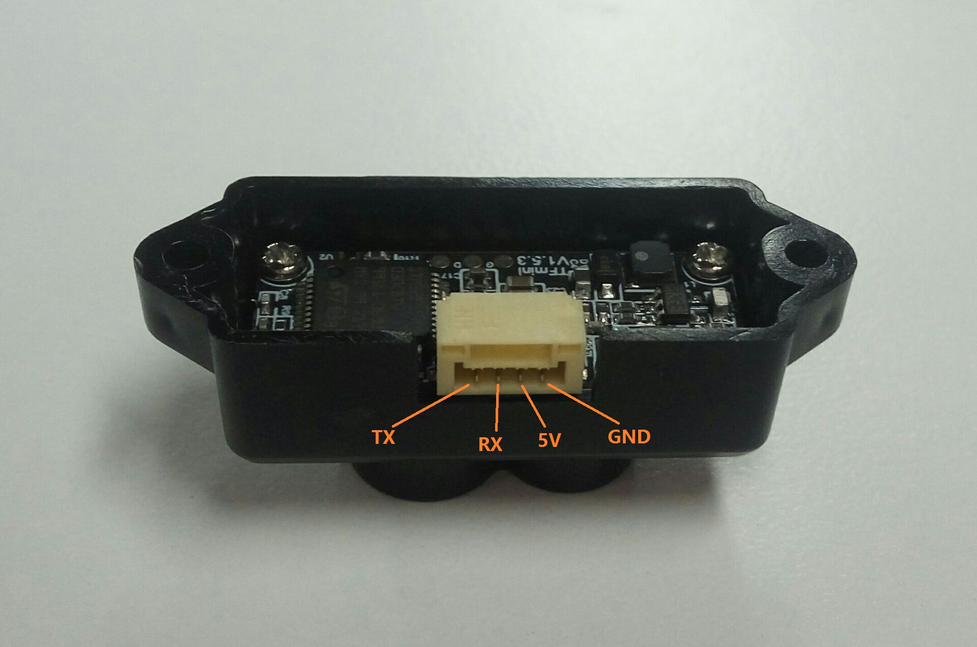
@Asterion_Daedalus Hello, hope you see this. If you need to make a cable for TFmini by yourself, you could check this picture with the connector wire order. The connector model number is GH1.25-4p, pin spacing is 1.25mm. It’s easy to make a cable by yourself or weld wires to the connector.
1 Like
Hello David and thank you for your post.
I have a tf mini installed also as a forward sensor, only in my case so far i had taken power from the GPS cable hack.
In this post TF-Mini-Obstacle Avoidance Issue 3.5.5 i have described an issue i have had with it in GPS navigated mode.
Have you come across anything like that?
Dear Siya, i hope you can look into my post also.
Thanx in advance for your time!