@Marc_Dornan I know that Mirko has successfully tested it on the BBMINI using 5 Ghz dongles.
Good to know that it has been done.
Oups sorry, I just checked and that was on a Pi Zero, but it should be possible, problem is that you need extra components like a USB powered hub
I see. Or alternatively could we run a PiCam and OSD with a conventional VTX. I could make a stab at the porting as these have been done for the Raspberry Pi.
Hi all! I am currently running Ardupilot (Arducopter 3.5.2) on a Beaglebone Blue and I would, in a separate python script, access the data coming from the ADC and the I2C ports (some gas sensors will be deployed there). I run Debian GNU/Linux 8 (jessie) with kernel 4.4.91-ti-rt-r137 and my DTC Version is 1.4.4. Up to now, I am able to access the analog port (thanks to another ardupilot user!) with the RoboCape rc_test_adc C code. Importing the Adafruit library for either the adc or the I2C in a Python script returns a RuntimeError due to a conflict with the standard Cape. If someone could help me, I have two questions for you:
- how can I access the I2C?
- I have plugged the Ublox M8N GPS into the GPS port, but I am not able to get the GPS work. I run Arducopter by “arducopter -A udp:192.168.7.1:14550” to connect to the laptop via USB. On Mission Planner, I see correctly all data except for GPS (there is the “No GPS” message). I have tried by adding the “-B” option with all /dev/ttyO* or /dev/ttyS* paths but nothing happens. The Serialx Baud and Serialx Protocol values are set correctly in Mission Planner.
Sorry for the inexperience, I am quite new both to the Ardupilot and the Beaglebone world.
Thanks for your time, kind regards
Luca
Solved it. Both Telemetry and RC. I was having two different problems on two different radios.
For the benefit of others who might use the pre-compiled ardupilot-blue, I’ll broadcast my noob mistakes here.
The 3DR Sik V2 telemetry radios were fine. The BeagleBone and ArduPilot software were fine, the problem was that I was using UT0 rather than UT1 on the BBBL (whose pins are preconfigured for telemetry in ArduPilot-Blue). The command switch that ultimately worked was:
–C /dev/ttyS1
and for GPS (which had stopped working)
-B /dev/ttyS2
Then, on my RC link problem, I’d failed to successfully change the output from my ezUHF RX to PPM on Pin 1 using the Immersion Tools software and USB connection. Seems I hadn’t hit the “Upload” after toggling my choice.
@axelisart @Marc_Dornan @james_pattison good news , ADC is on the way 
I will notify once its in master and that the new kernel is available

2 Likes
Hello all, I need help with choosing connector wires for my components. I have a 3DR Radio V2 that I will be connecting to the BeagleBone Blue and also my RC Receiver for PPM. Where can I connect these and which connectors will I need to buy?
@Thalaivar Have you read all the documentation on Mirko’s site ?
https://github.com/mirkix/ardupilotblue
Al the important information is there.
Also you can read all the replies on this blog, on reply 39 there is a picture showing how to connect the receiver.
For a more detailled pinout I suggest you look at the schematics:
https://github.com/beagleboard/beaglebone-blue/blob/master/BeagleBone_Blue_sch.pdf
There is the Bill Of Material if you look at serial connectors:
https://github.com/beagleboard/beaglebone-blue/blob/master/BeagleBone_Blue_BOM.csv#L20
It shows JST_SH_4 , if you do a quick search at aliexpress , you will find a lot of options
True but I cannot identify if the JST-SH-4 connector will fit my receiver, (it is an FS-X6B receiver), also, JST-SH-4 is a 4 pin connector whereas the PPM connector will be obviously 3 pin, so is the info even correct? Also, there is no mention about connecting telemetry radios.
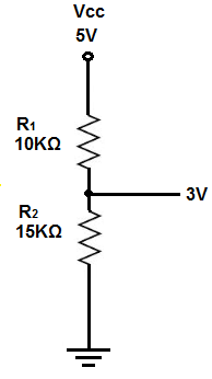
You have to build the cables and I see you receiver is 5 volts, so it should be powered using a 5 Volt source and feed the PPM using a voltage divider to pin 4
Again, I am okay with building the cables, but which connector do I use for the DSM port???
@Thalaivar Maybe I dont understand what you are asking
Receiver
The RC receiver signal has to be connected to connector E4 pin 4. This pin is a multi protocol pin (S.BUS, PPM-Sum, Spektrum Satellit DSM), the protocol will be automatically detected. Make sure the signal does not exceed 3.3 volts, otherwise your BeagleBone Blue can be damaged.
1 Like
So if I get it right, I have to separately power my RC Receiver with 5V, convert the signal back to 3.3V and then build the cables to feed it to the BBBlue?
exactly
You can put the resistors inline the cables and cover with heatshrink tubing
1 Like
But will the DSM port read PPM Signals? Mirkix’s docs say PPM-Sum, is that the same thing?
Yes, PPM-Sum is the correct term for ‘‘sequential stream of pwm pulses’’
As for the telemetry you dont need voltages divider , the Uarts can read 5 volts.
Dependig on the power, you could feed from the BBBlue 5 volts supply.
And, once again, refer to Mirko instruction to map the telemetry to the right port
1 Like
Brilliant Patrick.
I am looking forward to it.
Thanks for your efforts.
just getting into ardupilot with a bbblue. I have instleed the latest ardupilot running with rover-blue. I have the board connected to mission planner and when I move the board it shows the gyro moving in mission planner.
My question is, assuming I got to this point and did everything correctly, how do I test my servo is connected and working with mission planner. It is connected on channel 8 on the servo rail and I am going to the servo screen (the one that’s on the flight data screen with low, high, toggle buttons) in mission planner to toggle it. But when I do, it doesn’t move. What am I doing wrong?
Are you supplying the servo rail ?
You need to use the Battery connection in order to get the servo power activated