Hi!
I have an old Walkera Tali H-500 trying to retrofit a Pixhawk clone from HK.
Problem is that I cannot monitor Voltage or Current.
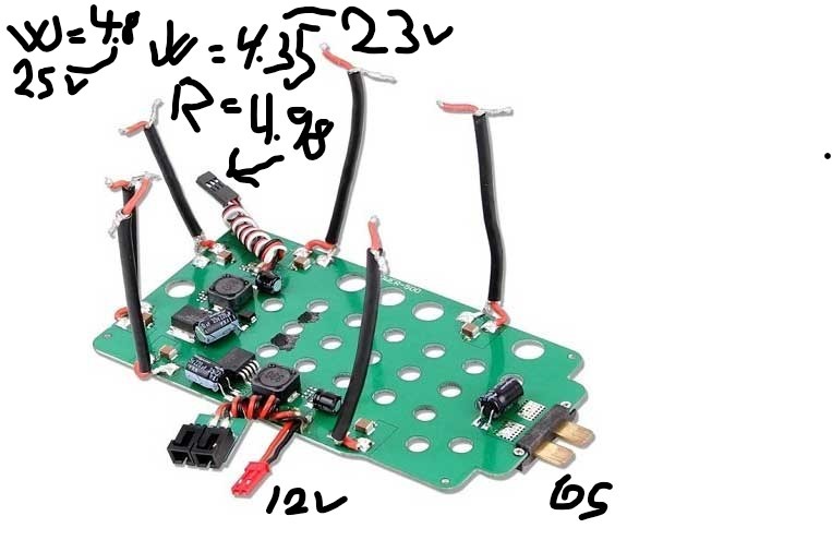
Tali H-500-Z-18 Powerboard connect to Pixhawk
Howto power Pixhawk and meassure V and A ?
Connected a Ubec to the 12V output or the 6S on the powerboard. This will supply about 5,2v to my 6pin Pixhawk Power input: Pin 1&2=5.2v+ (red from ubec) Pin 3=4.80v+ (white from powerboard at about 6S=25V) Pin 3=4.35v+ (white from powerboard at about 6S=23V) Pin 4=4.98v+ (red from powerboard) Pin 5= ground (black from powerboard) Pin 6=ground (black from ubec)
It seems like the 4,98v from powerboard does not change when 6S is drained, so I will not be able to meassure the 6S with the red cable. The white cable is showing voltage from 4.8v to 4.35v so mayby I can use this exept the video below state this white cable is for current sensing. The 4.80v from powerboard will decrease to about 4,70v at full Throttle, then return to 4.80v when Throttle is off. Battery monitor will not update neither connected pin 3 or 4 on the Power port on Pixhawk and set up is done with Analog Volt and Curr - 0 Other - 4 Cube or Pixhawk.
The 4.35v from powerboard will decrease to about 4,22v at full Throttle, then return to 4.35v when Throttle is off.
The powerboard is for a Walkera Tali, and the servo-cable with 4.80v 4.98v and ground is normally connected to the Devention controller FCS H-500 check power port. On this Tali its possible to meassure the 6S voltage so I believe they use the white cable for this. The red cable will supply constant 4.98v to FC. No schematics found.
I have also tried with the Ubec connected to the 6S terminals, same situ. I am stuck here.
Here is a video from Mr. James Reed who state howto do: Tali h 500 pixhawk upgrade preparation section 2 - YouTube
Pixhawk PX4V2 with AC V4.1.0 MP 1.3.75 build 1.3.7883.26333
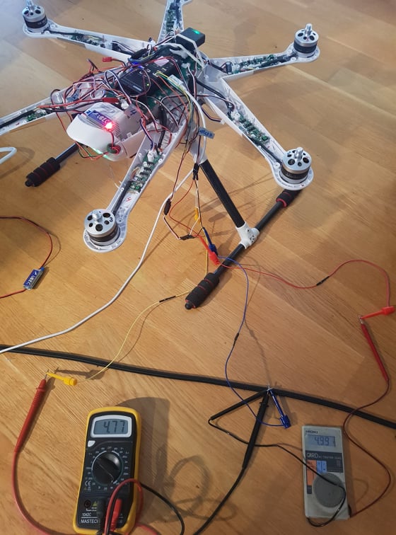
Anyway, Short I tested with a Powermodule V1.0 and this works.
If we have 12.8v the Pin 4 will get 1.19v and with 11.2v Pin 4 will get 1.02v so for these low volts around 1-2v the sensor works. What is the max voltage (functionwise) I can apply to Pin 4?
I also tested the current by connecting a 12V 55W to the output from PM. Pin 3 will get 0.044v and I say this is about 4.3A I got current readings also. What is the max voltage (functionwise) I can apply to Pin 3?
The most important for me would be to get Volt readings running.
I struggle to solve this and some tip from community would be great.
Regards Espen
Its always good to discuss with yourselves, you get the answer you want. Anyway, I now use the white cable that I meassured from 4.35 - 4.8v. Then I added a 9M ohm resistor (9times 1M ohm in series), now operating below 0.5 v and I use this as input to volt-sensor on pixhawk power port pin 4 and it works.
In original Tali PDB you have only voltage sensing pin (white) and power supply for FC (red +5V, black GND). Tali FC uses 6,6V input to sense Voltage. So if you want to use it on Pixhawk, you could change to Voltage monitoring on pin 15 and connect there that white wire. Settings for rate is about (5,something). But you could use 5 and then enter corrected measure voltage to correct it.
If you connect white wire to power port in to pin 4 you could damage it.
Rest of wires (red,black) you could use as spare supply voltage for Pixhawk - and add Zener diode.
 Anyway, I now use the white cable that I meassured from 4.35 - 4.8v. Then I added a 9M ohm resistor (9times 1M ohm in series), now operating below 0.5 v and I use this as input to volt-sensor on pixhawk power port pin 4 and it works.